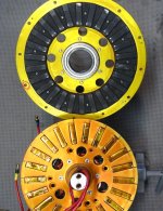
APL's DIY axial-flux motor

Thanks for the kudo's, it's been a long time coming, I think this project was first talked about almost exactly
one year ago, on Sept. 2nd, 2018. Thanks for all the support, I couldn't have done it without you! :)

I spent most of the day trying to get a video made, and into Youtube, and after uploading, downloading, compressing,
and cursing, I finally got it accepted. Too bad it's such a bad video, but at least it proves that it works, and lets you
see this thing in action. :)

Video;https://www.youtube.com/watch?v=IR0KenoPWpM

[youtube]IR0KenoPWpM[/youtube]


I pretty much gave it full throttle all the way up to about 25.5 mph., thats when the motor start's to do it's 'grind'
thing, after that I had to baby it a bit to get more speed.

No worries, we'll get it fixed yet. Now I can tear it down and see what's rubbing, and beef it up,.. plus add another
layer of windings, and try it again. Then it's on to the GR10 plates, and new core arrangement, which will probably
take it into the fall, and the end of the riding season for me.

This winter we can chew on the next version, hubbie motor, and see if we can get the Nep. his test motor going! :)
 
I saw it on youtube first cuz i subscribed to you. Congrats again for getting this motor to the phase where it actually spins the wheels. :)
 
Thanks Vanarian, and neptronix, it does feel good to get to this point! I can finally relax a little bit, since I didn't fall
completely on my face with this build. Whew! :confused:

Lebowski, after thinking about it, I think your right, a proper controller is in order! And your creation would be the
perfect choice. "Endless Sphere associated products should always be used". :thumb:

I have to admit that the controller is just a magic box to me at the moment, and I really need to dissect one in order
to get the whole picture of the system. The best way to learn about something is to build one.

Might be getting over my head again,.. I'll have to start studying the Lebowski controller post's, and see what I'm in for.
 
After riding the bike for a while, I took the motor back out, and tore it down to see what the issue is with
the high speed/power rubbing inside.

I expected to see a lot of damage to the magnets, and at least a few cores, but I didn't find much at all.
It appears that the kapton tape and paint form a good slick bearing surface, so there isn't much to see.


Rotor rub..jpg

I spun each rotor, to checked the out of round, and found none. Then I checked the stator cores, and mounts,
for side play, and also found none. So that leaves the drive bearing axle surface as the probable culprit.
Shoddy workmanship will get you in the end. :(

If I can get that fixed, it should solve the wobble, and power rub at the same time.

I ordered out some more 14 awg wire, to add another 10 winds to the cores, which is the next move. And
I've been looking at different phenolic materials for the new stator plates, and trying to figure out exactly
how that project is going to be done.
 
Can't help looking at ideas for the next design, and I'm liking the idea of a toroidal wound stator.

A wound and bonded silicon steel stator core is probably the easiest to make, and only a little
machining is needed, either 10mm slot's, or a drilled hole, as per stan.distortion's idea.

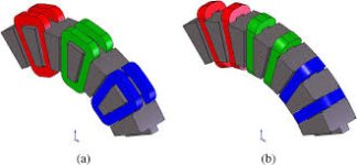
I've been looking at quite a few examples, and see that there are several ways to wind the coils,
and arrange the PM magnets. Theres the standard 'around the tooth' method which makes for a
common N/S rotor pair, and then theres the toroidal 'around the middle' which makes for a N/N,
S/S rotor pair.

Axial stators.jpg

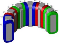
My favorite is the torrid wound stator, because of the easy winding, and the non-wasted end windings.
Since each tooth becomes a mono-pole this way, there needs to be twin coils in each slot, on both
sides of the tooth to make it work. Otherwise the wiring would have to be ABC,ABC,ABC, and there
are very few motor schemes that use that.

Dual coil torid wound stator.jpg

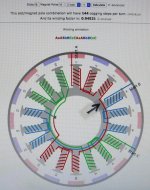
One question I have is,.. I see in most all of the wiring arrangements that there is an interference point
between each set of phase coils,.. that is a north-north or south-south point on the back iron. Between 3-4,
6-7, 9-10, etc.

IMG_1983 copy.jpg

Seems really inefficient, as the fields are fighting each other there,.. like poles repel and all,.. :?:
So I'm going to assume that the phase rotation's diminish enough at that point, as to make it negligible?

The other question that comes to mind is, if the rotors are N-N and S-S on each side of the stator, (on a
torid wound stator), then they would naturally repeal each other as the flux travels through the cores.
Wouldn't this make it a non-coging, or zero drag rotation under no volt? Advantageous for a hub motor.
 
just fyi, remember that drilling and the milling of the wound stator will cause burrs and those burrs can short your stator winding. afair silicon steel is hard to be eiched by acids so the quality of the milled stator could be questionable. so that's why they use stamping or EDM machining for this purpose.
also please keep in mind that back iron of stator core should be at least 80% as tick as widest part of the teeths. if you wanna build dual-in-one stator core, the back iron tickness should be doubled too.
 
Agreed, machining silicon steel is not really recommended, and in fact anything you do to work it is supposed
to be followed up with an annealing process,.. usually done in mass production, where it is cost effective.

Shorting of stator steel is something to watch out for, but lots of transformers and motors have welded stacks,
and every motor I have, shows a complete short across all the laminations. I'm always learning about this,
but I think that it has more to do with the frequency's involved? Hub motors generally don't have very high freq.

This is home brewed DIY, and I hope that I can grind the milled surfaces, (sandblast?), to remove most of the
burrs. The copper windings will be insulated by some form of tape or plastic, of course.
A lot of hope, and I'm just looking at the design at this point. Thanks for the FYI, I need to be aware of all the
pros and cons. :thumb:

As far as the back iron thickness,.. it's really not very clear (to me) as to what and where that is on this design yet.
Theres the tooth on each side of the stator, and then, the iron in the coils on each side of the tooth, for a single
segment.
The picture below is not that great of a representation, but show's one segment.

single segment torid stator.jpg

Still trying to figure it out,..thanks for the info., any help is most appreciated! :)
 
Hi APL,

Can you provide the source for those illustrations? I'd like to see the rest of the machine. Thanks.

major

BTW, just because hub motor RPM is low doesn't mean low frequency. It likely is higher than your 60 Hz motor or transformer.
 
You bet major, it's one of those PDF files that takes a while to download at first though, at least, for me.
Maybe you'll have better luck.
noguchi-lab.com; http://www.noguchi-lab.com/pdf/2016/ecce2016.pdf

I found it on an Images search; https://www.google.com/search?hl=en&tbm=isch&sxsrf=ACYBGNSHbhAxfZ25vQWd6KAxDdYQpFBVLw%3A1567729318773&source=hp&biw=1680&bih=1012&ei=pqZxXYq7LNK4-gTHnJKYCg&q=toroidal+wound+axial+flux+motor&oq=to&gs_l=img.1.0.35i39l2j0l8.20198.22124..27084...0.0..0.136.270.0j2......0....1..gws-wiz-img.eTZQQCel1ig

It's a very interesting machine, in that they use three sides of the stator, both axial, and radial.
I suppose it's even possible to use all four sides, except that you have to hold the stator somehow.

I'm not sure what they're up to however,..I haven't read the whole article, I think they're using the radial
power to automatically adjust the field weakening of the axial, or something. A bit beyond my understanding.

A very respectable build! Those guys aren't holding anything back. :!:
 
I think you are correct about lamination shorts: my understanding is even with one part of a lamination shorted (say the outer edge) it still mitigates against eddy currents in other parts as the eddies are very small (I'm not sure if the size is related to frequency). I'd guess there are caveats though, like not wanting to have the short in a high-flux area and being careful that multiple shorts in different areas don't add up to a significant loss.
 
While the torroidal winding is interesting, I don't think it will be very efficient as you have a lot of flux passing through the core that's not going to the gap. This means more current (and more resistance losses) needed to get the same flux in the gap. You really want all the flux in the gap and not any bypassing it. Your original design is very good in this respect.
 
Well, it's always good to explore,..can't help but learn. I'm beginning to realize the same thing, that the torrid
design may have it's place, but I don't think that it's here. Contradicting core flux's, excessive flux path length,
and excessive steel weight in the stator, plus questionable lateral strength, are starting to bring me back to the
original design as well.

If it's bike, then it needs to be light. And as a basic modle for experimentation, this design is working fairly well
for the moment.

All I really need to do is replace the square cores and PM's with trapezoids, and make some refinements to the
construction, (plus an 18/16 design), and I think it's good to go for a while.

I need to look into laminated core construction again. Maybe slicing a wound and bonded stator ring is the way to go.
Also, I might have found a good way to make the trapezoid PM's in custom sizes fairly easy and cheaply, by using
stacked smaller magnets, which are cheap and abundant.

laminated trapezoid rotor magnets.jpg

I tried belt sanding the ends of a few Neo's, and found that it's not 'too' hard to put a short angle on the ends.
I know that the process is toxic, so I would definitly move the operation outside, and wear a lot of protection.

Of course, custom made PM's are always an option, but I'm not sure they would be cost effective for one-off use.
Could be wrong about that.

I need to do a drawing, and see just how big the magnets are going to be, before I can go any further on that idea.

Sounds about right PunxOr, it will all work, but comes down to a percentage of lost efficiency. Ideally, they should
all be coated, it would be nice to put a coat of paint on each one. I know in the old days, they placed a sheet of
paper between each lamination!
I think the eddy current's moving through the length of the laminations, far outweighs any loss at the ends. :?:
 
I've ground some magnets before. Makes sparks like crazy. It would be best if done wet to prevent dust, sparks and overheating the magnets, which will demagnetize them.

It's also quite challenging to tile the magnets together. The pieces will strongly repel each other and want to flip over and stick to the adjacent magnet. You have to force them into position with clamps of some sort and wait for the glue to harden. I've done it on a few builds but it was a lot of work.
 
fechter said:
You have to force them into position with clamps of some sort and wait for the glue to harden.

Seems like resin or aluminum clamps would be handy for this.
 
IIRC, the actual magnet under the nickel coating is easily corroded, so you want to replate them or coat them with something to prevent that.
 
APL said:
As far as the back iron thickness,.. it's really not very clear (to me) as to what and where that is on this design yet.
Theres the tooth on each side of the stator, and then, the iron in the coils on each side of the tooth, for a single
segment.
The picture below is not that great of a representation, but show's one segment.

single segment torid stator.jpg

Still trying to figure it out,..thanks for the info., any help is most appreciated! :)
please have a look at the picture of axial flux stator core which i've designed for my build (yes, you and lebowski inspired me):

stator core with exp.jpg

here "T.W." means tooth width, "B.I." means heigh of back iron of the ctator core. afaik the best value for B.I. should be at least 0.8 of value of the T.W. or bigger. if you make it less the system is not the most efficient one - you'll get some losses. if you make dual stator, you make the core like two of cores mentioned above connected by back iron sides. that means you'll get doubled B.I. figure.

in my design the core is relatively thik because i wanted to have maximum airgap square within 100 mm of diameter and i decided to go with 12n10p scheme.
 
Welcome to the trail of tears damirsky, good to hear that another motor build is afoot! :thumb:
Looking forward to all the new information, and sources, you will uncover. :)

I'm curious as to where your .8 value is from? And I wonder if it's need's to configure the area of
the tooth into a square, and then derive BI thickness? Just a thought, I'm not aware of the formula,
so it's all new to me.

What's the planed diameter of your motor, and what, (if anything), are you thinking of using it on?
 
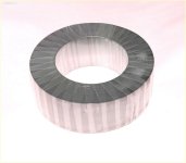
I was looking around on the bay, and found these toroidal cores for transformers. quite a few different sizes,
but all 2" thick. Haven't looked elsewhere yet.

Whats nice is that they use grain oriented laminations that are only 12 mil thick!, or .012",.. are factory bonded,
and fairly cheap, compared to what it would cost to make one. :?:

Theres a very large one that is 4" ID, and 8" OD, that would work for mine, that's worth considering. :idea:
A lot of cutting and machining, but I get twice as much as I need. Hmmm, going to take some looking into...

torid core 12mil. laminatioms.  4%22 ID x 8%22 OD..jpg

E-Bay Toroidal Core'shttps://www.ebay.com/sch/i.html?_from=R40&_trksid=m570.l1313&_nkw=toroidal+laminated+core&_sacat=0&LH_TitleDesc=0&_osacat=0&_odkw=laminated+core


Also found this interesting axial motor design,.. I can't figure out what the coils look like though. Food for thought.
Might have potential for a DYI design. I like how thin it is.

p cake 8.jpg

Bling Bling Axial motor; https://www.ebay.com/itm/Axial-Flux-Flat-Frameless-Permanent-Magnet-Generator-380V-3-0kW-3600-RPM-3-Phase/174001388230?_trkparms=ispr%3D1&hash=item28834a7ac6:g:ck8AAOSwuUlcH73h&enc=AQAEAAAB0BPxNw%2BVj6nta7CKEs3N0qUx64yPYYSirQ0SOZHp96Hjg6yiZWju5Cyi4oeZsSEMNiYxdJsnW2w81IbelXUvTvXAUE67CwGnwNmOH%2FjBT8g5ALfgoI0c5lXf%2FbNeM1pjRYUCMHdb8bOamw%2FLorLZL0Ddw8d8WJWEBxVkQfZu1yDqDrG09X6yFEK78WhjNA0ZzSy95gqxwst9wffrjLehDzUpL2vq63EPXPv8ZEiYvXa4eV1W8udtNLrb4JBvhvvhURv5eVDZHX0QYN6Im1FfRHQybc8L5qEGE8KVWRKORmuijMw1h2q5Cii9ZZddmBmfwodnXs%2B1IbRY%2BymmdmTKNbW3aDGCYBmmI268GeRWz9JKLFESL3mcbN%2FAy80xTBmN13f5TR58fkmmoEpK0tOJobwskYATYLpiR6ThI6GoPVIBuJ15uEkU0o7FNEXMsYggLmI94GKiP7APpIfW2PrYvIZkPA7%2BMroHy3KPntJvZmQG%2FGQKwrujvv%2FWUlTt3KDCrdaHhsR9%2Ba2O2qpaJuCeDclvbJ%2BBhtvKvU8uMgrQmkmy6miqlHzrPK0x8xhr6KCqiqwtV%2FCcKE%2F9xgCVZNJVcdFFHdF1ASyu15zdDoclsMCL&checksum=1740013882301696ee0870964b0f88f1e9e858d09a5b
 
APL said:
I'm curious as to where your .8 value is from? And I wonder if it's need's to configure the area of
the tooth into a square, and then derive BI thickness? Just a thought, I'm not aware of the formula,
so it's all new to me.
one gentleman from russia, who is PhD in electric machines and experienced builder of motors, said me that.

What's the planed diameter of your motor, and what, (if anything), are you thinking of using it on?
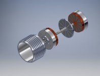
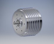
i plan to use it for the next project of middrive bike but no idea when will it happen. diameter is 130 mm, width is 87 mm (without shaft lenght), estimated weight is around 5 kg. i decided to go with double stator and single rotor (like in some of Golden Motor motors) layout, rectangular wires (8 turnes, cross-section area is 4 square mm per one stator coil) and fiberglsass shaft and rotor.

motor assembly.jpg

motor disassembled.jpg

stator cores shall be made from toroidal transformer core i ordered from china with my design.

transformer core.jpg

this is non-oriented silicon steel with 0.35 mm of tickness. unfortunately i couldn't gen any info from producer about sort of steel used for this core. i plan to make stator slots by simple diy edm machine.

EDM machine drawing.jpg

already ordered the frame from outsorce cnc shop:

EDM frame.jpg

sorry for intervention with my pics to your topic. i was thinking about opening of new thread but i was too hesitate.. :roll:
 
Wow damirsky, your a lot further along than I thought, very impressive stuff! Don't worry about thread intervention,
everything is welcome here, theres plenty of room, and were all motor perv's,.. so we love to see it!

The collection of knowledge and info./material sources is whats important. And if it's axial, then this is a good spot.

I love the flat wire coils, your motor is shaping up to be an all time great,..it will be very interesting to watch. :thumb:

Your EDM machine is a monumental endeavor as well, I guess I don't know much about them, but now I'm going to
have to look into it. I'll check out Wikipedia. That's going to be an interesting build by itself. :)
 
APL said:
I'm curious as to where your .8 value is from? And I wonder if it's need's to configure the area of
the tooth into a square, and then derive BI thickness? Just a thought, I'm not aware of the formula,
so it's all new to me.
i thought this point is not completely clear (for me :lol: ) so i decided to talk a little bit more about it. :D

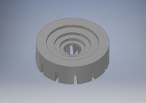
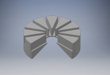
as far as i understood the ideal shape of my design of stator core should be like this (i made a square cut for better transparency):

cone shaped stator core.jpg

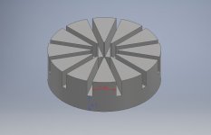
as you can see the tickness of back iron depends on width of the stator teeth so back iron is cone shaped. this design provides best efficiency and weight but unfortunately is hard to build. i've seen some pictures (i can't find now) with suggestion of the design of stator core like this one:

amphitheatre shaped stator.jpg

it is actually made of a few wound cores with different width and diameters and then inserted each inside other. it is a bit easier to craft but any way is harder than a common wound stator.
what would you say? will you bother yourself with that stuff? :D
 
Back
Top