Axiom: a 100kW+ motor controller

Hackey said:
I am having problem running in sensorless.
My motor doesn't start it just jerks and on sampling BEMF in sensored mode it is 1volt peak to peak not more than that.
I don't understand your test... if your setup is using hall sensors, in the background the firmare is still running the sensorless observer because the resolution of a hall interface is 120°. You need <3° resolution for proper field oriented control, so the coarse approximation is based on Halls, but then it relies the observer algorithm, which relies on R, L and flux linkage parameters, which are calculated in the FOC parameter detection.

The hall removes most of the guesswork at 0 rpm, but it still needs good parameters to work well.

Like the resolver interface, you need to go to the Hall Sensors tab and run the "Detect hall sensors" routine so the firmware can fill the correction tables.

But you said you have 1V peak to peak... if thats at 0 RPM its okay. At zero RPM the motor produces 0V of BEMF. If the motor is spinning fast then it should certainly have a strong BEMF and you should be able to clearly measure it at the motor leads and at the ADC pins.
 
OMG, huge thumbs up! My jaw dropped at the first post and I was at least 3 pages through before it closed again, you're genuinely going to change the world with what you're doing here :bigthumb:

Why oh why didn't I come across this a couple of years back when I was looking into EV drives? (or this forum for that matter, incredible resource). I got as far as writing the basics for an IGBT controller in AVR ASM but chickened out with the IGBT driver circuitry, not my strong point and didn't want to risk letting the smoke out of an IGBT module (and possibly myself too). That IGBT module (PM100CSA060) is still sitting here gathering dust, a 3 in one unit but if this is suitable for driving it then I'll happily risk sacrificing it to the gods of testing.

Still have a few pages to catch up on in this thread and looking forward to every post, great project.

EDIT: Finished reading through, a question on motors (if not too far off topic). New to the forum (signed up for this thread), are there any good threads on using automotive alternators as motors, using (wound rotor) generators as motors or converting induction motors to permanent magnet? As far as I can see they all seem to be good low cost options for high power motors for EVs (if only a suitable open source controller existed! ;) ) but there doesn't seem to be much info on (mis)using them that way. Very interested in testing those options but there are bound to be pitfalls. Thanks.
 
Hi Stan,
that's a rather small module, the control board will look giant near it. If you figure out a way to install the 3 current sensors, the DC link and the gate driver connections it should work.
It looks like a lot of work for only 100A, but if you are going for lethal voltages I don't think there is a safer control board than this one.

Now some good news, Axiom finished *first* in the first stage of the hackaday prize
leaderboard.png


I put there an interesting post that explains a bit more about the FPGA
https://hackaday.io/project/164932-axiom-100kw-motor-controller/log/164630-lets-talk-about-the-fpga
Its barely an overview, it doesn't go into the details of sinthesing the hdl code, testbenchs, etc, but it puts together several things about the fpga.

An interesting note about enclosure sealing, its also a glimpse about what is coming
https://hackaday.io/project/164932-axiom-100kw-motor-controller/log/164337-waterproofing

And a feature post about hackey's bike
https://hackaday.io/project/164932-axiom-100kw-motor-controller/log/164611-highest-power-vesc-bike
 
Here is some test results we had a while ago when doing double pulse tests to validate the powerstage and our custom DC Link.

First of all, I coded some handy functions and commands to perform a double pulse test from the VESC Tool GUI.

double pulse test 1.png

From the command line I can easily and accurately set the timing. This is a firmware patch that will be kept at our lab as tool, we won't distribute this binary but we can receive any powerstage and do this testing for you in our bench.

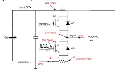
A test setup is something like this:
3032905982_1_3_qi4P0P34.jpg


You want to observe the switching characteristics of the drive at peak current load. To do that you keep the top IGBT in OFF state (Our powerstage will keep the top gate at -9Vdc)
* Turn ON the bottom switch and let the current through the inductor increase to the desired test current
* Turn OFF the switch and observe the voltage overshoot
* Wait a minimum amount of time and turn ON the switch (rated current is still flowing through the body diode od the TOP switch)

We have some handy support math to calculate the construction of the inductor, the required inductance and time required to reach a set current.

A test setup looks something like this:

View attachment 3
Note that voltages are measured with differential probes to avoid damaging the oscilloscope, and measurement happens directly at the IGBT terminals


20190613_122347.jpg
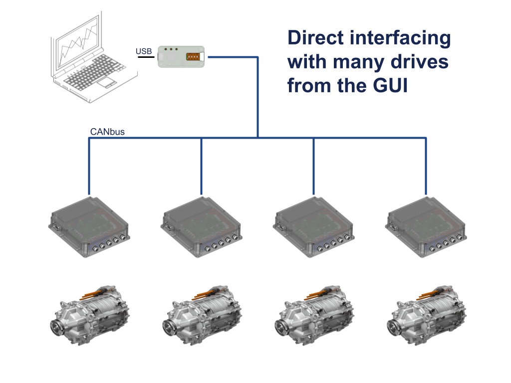
On the top left you can see the inductor for the test. We communicate to Axiom through the isolated CANbus interface so the laptop is isolated from the device under test.

Double pulse test result at 375V 450A:
View attachment 1

And zoomed in:


Yellow trace is Collector voltage (to measure overshoot), green trace is phase current, orange trace is TOP IGBT gate (to observe miller effect).

The overshoot is caused by the inductance of the path between the silicon switch and the DC Link capacitor. This includes the internal IGBT module wiring, the connection to the DC Link and the internal DC Link ESL. We tested other DC Link and ours performed better during this testing. Overshoot can change wildly if your DC Link is not carefully designed; we have a 100V overshoot, imagine how bad can it become if the DC Link ESL is left unchecked.

Overshoot must stay below the IGBT rated voltage, which is 650Vdc minus some buffer %. If we were operating at higher DC bus voltages we can either test snubbers, slow down the turn OFF time or just use a 1200V rated IGBT.

Miller capacitance between gate and collector of the TOP switch will try to turn ON that switch when its supposed to be off. We check that the gate sits at -9Vdc and miller can only pull it up to -7Vdc, thats good.

Something really good about double pulse test is that you can measure the switching losses, and we have access to a very good rogowski current probe but its only capable of measuring 300A and we are more interested into the 500A to 800A range. We did measure emitter current but the sensor can't properly track the slewrate. Maybe next time.

Double pulse testing is something *every* controller design should have endured, you don't know how the powerstage works until you observe it.
 
I'd like to discuss qoutes on double pulse testing some of my controllers. Is that more suited for PM?
 
shaman said:
I'd like to discuss qoutes on double pulse testing some of my controllers. Is that more suited for PM?
Yes, PM me. Basically the client pays the fedex shipment, import taxes and the hour(s) the test takes. I'll make a difference if is an open source and kicad-based project. Those are better contributors for the vesc project.

And for those who missed the newsletter, here is the control board datasheet
 
Hey, really cool project. I want to build one myself also, for slightli lower power, 150V/200A (mayby change a bit (use fets instead of igbts, slightliy different layout, etc)). Should I follow the "paltatech" design, thats ~2 years old? Seems like it has already been replaced with newer "axiom" files in VESC github, that you havent released yet?

Thanks
 
knuthcomi said:
Hey, really cool project. I want to build one myself also, for slightli lower power, 150V/200A (mayby change a bit (use fets instead of igbts, slightliy different layout, etc)). Should I follow the "paltatech" design, thats ~2 years old? Seems like it has already been replaced with newer "axiom" files in VESC github, that you havent released yet?
vesc firmware supports both RevB (hw design you saw in github) and RevD (black axiom boards). For revB support you just add the line
Code:
#define HW_PALTA_REV_B

here https://github.com/vedderb/bldc/blob/master/hwconf/hw_axiom.h#L38

Our current plan is to open the design the same way as the official vesc does, and for the same reasons. We keep RevB complete hardware project files online as a reference design, and provide RevD schematics for reference (not ready yet, but will happen soon).

Designing a new powerstage is a huge effort, you are likely on your own there as I'm swamped with developing and consulting regarding Axiom controllers.

Right now I'm working in native CANbus support to VESC Tool, so we can finally avoid using the USB interface and just use the isolated canbus interface with an off the shelf canbus<->usb adapter. The other big task is enclosure design, and since it also takes care of coolant flow its quite a challenge.
 
marcos said:
Designing a new powerstage is a huge effort, you are likely on your own there as I'm swamped with developing and consulting regarding Axiom controllers.
I completly understand you are busy, its just my own enthusiasm to build this. I already have ton of experience in electronics and access to proper lab to do the testing.
I have Toyota Prius power stage laying around, that I plan to use.
 
knuthcomi said:
marcos said:
Designing a new powerstage is a huge effort, you are likely on your own there as I'm swamped with developing and consulting regarding Axiom controllers.
I completly understand you are busy, its just my own enthusiasm to build this. I already have ton of experience in electronics and access to proper lab to do the testing.
I have Toyota Prius power stage laying around, that I plan to use.
Awesome. We have an adapter board template for those who want to integrate an axiom control board into an existing or just different system.
adapter template.png
Its not my current priority as it tacitly means that the user has to go through several designs and test steps before being able to provide us with feedback -every control board we ship is a precious data generator for the design-. But well, the kicad files are available for customizing the template.

For general delight, here is a log update regarding the enclosure
https://hackaday.io/project/164932-axiom-100kw-motor-controller/log/165257-mechanicals-part-1

Its still a long way to go, but we see improvements every week.

enclosure_draft.png

Some things are not quite set in stone, but I think we're in the right path. Most applications just can't have the control board exposed.

Here is the behind the scenes showing the first strokes
[youtube]uqNdVlWmvLM[/youtube]

And the enclosure-less test bench assembly
[youtube]aaUYyAKyi-4[/youtube]
 
Awesome, before I order components for main board, do you have any old assembled RevB boards laying around that you are willing to sell for a reasonable price? It would save my assembly cost and help your project a bit.
 
Abricosvw said:
what do you think when we can start use IPM motor ...
You can give it a try anytime without Max Torque Per Amp. The motor should spin, it just doesn't use the reluctance torque.
If you feel brave you can build the VESC Tool guI and use a firmware built with MTPA support from the testing branch.

I can send you the firmware binary, but I don't think I can package a VESC tool for you, I imagine the GUI binary will have dependency issues.

Did you get any further with the resolver?
Abricosvw exposed a bug in the resolver circuit, it is not protected against too low resistance in the EXC coil of the resolver. If that coil is less than 33 Ohm, too much current will flow and the EXC amplifier will overheat. I added a note about this for the next revision, meanwhile I can cut a trace and add a series resistor between amplifier and the connector, or add the resistor to the wiring if the resolver has such low resistance.
 
marcos said:
Abricosvw said:
what do you think when we can start use IPM motor ...
You can give it a try anytime without Max Torque Per Amp. The motor should spin, it just doesn't use the reluctance torque.
If you feel brave you can build the VESC Tool guI and use a firmware built with MTPA support from the testing branch.

I can send you the firmware binary, but I don't think I can package a VESC tool for you, I imagine the GUI binary will have dependency issues.

Did you get any further with the resolver?
Abricosvw exposed a bug in the resolver circuit, it is not protected against too low resistance in the EXC coil of the resolver. If that coil is less than 33 Ohm, too much current will flow and the EXC amplifier will overheat. I added a note about this for the next revision, meanwhile I can cut a trace and add a series resistor between amplifier and the connector, or add the resistor to the wiring if the resolver has such low resistance.
Hi
Unfortunately not ...I do not have the opportunities to test resolver now ... I restored everything to working condition (after the last test) ... Now I work with a gasoline engine ... I have race july 20-21 ...I'm preparing and set up the car (engine) ...
 
I hope the race went well Abricosvw,

I just wanted to highlight here a couple of updates:

VESC Tool now can connect directly to a CANbus network
See details here:
https://hackaday.io/project/164932-axiom-100kw-motor-controller/log/165890-new-feature-gui-canbus-support

8679371563769117267.png
The end goal? Make it easy to have kickass instrument interfaces like this one. It only requires a beaglebone/raspberry + hdmi display + canbus adapter.
[youtube]QggBHHTWX3E[/youtube]
How to interface VESC Tool code (Qt5 C++) to that cluster example (Qt5 QML) goes totally over my head, I hope someone is willing to help us with that.

HighHopes deep dive on safety subjects
https://hackaday.io/project/164932-axiom-100kw-motor-controller/log/165717-deep-dive-shoot-through-safety-feature

2755021563160442328.jpg


There is a log about Arlin's new build... but I'll let him manage the pace of the unveil as we can't promise any date.
 
For those of us playing at home, CAN is the way automobiles and some industrial tech communicate digitally. It's a robust way of sending digital signals through noisy environments and it can be effectively isolated as stated in the hackaday article.

I have a feeling this can be exploited for some serious automation purposes. Combine these motor drives with an open source PLC and few other industrial bells and whistles and you got a factory.
 
:bigthumb: :bigthumb: :bigthumb:

I finally finished soldering boards and have done some basic testing.
Vesc tool reads currents, vbat and phase voltages. It doesnt read them accurately, but it just needs some fine calibration in the software.
Bigger problem is that it wont read HAL sensors at all, am ai missing something in the setup? I measured voltages on stm sensor pins and they change, but no movement in vesc tool.
Vesc tool also gives me overvoltage fault, I think this has something to do with mc conf file (according to hardware def file). Where I can find the mc conf file and change the parameters?
I will post pictures of my build later.
 
There are no pullups in the schematic for the HALL sensors. Maybe your sensors are open drain and need that?

The overvoltage is on purpose, its there so you can't use the default mcconf hardcoded in the firmware.

Go to general->advanced and set up a reasonable max input voltage for your system, and write the mcconf to the mcu. You'll likely need to tune the deadtime compensation. What ppwerstage are you using?
 
marcos said:
I hope the race went well Abricosvw,

I just wanted to highlight here a couple of updates:

hi
i'm still alive ...the race was not very good rain ...
I'm a little busy with school and work in the garage ...
but I think at the end of September or October I will return to full time again ...
but if anyone needs help... I am ready to help everything I can...

I also watch batteries ...
I realized one thing if you maky it yourself it will be very expensive (battery pack) ...
but i found battery pack is really cheap from ( Kia Optima Hyundai Sonata Hybrid Battery ) ...
cost approximately 350-500$
New Bitmap Image12.png
s-l500.jpg
 
Abricosvw said:
I also watch batteries ...
I realized one thing if you maky it yourself it will be very expensive (battery pack) ...
but i found battery pack is really cheap from ( Kia Optima Hyundai Sonata Hybrid Battery ) ...
cost approximately 350-500$

Yes, keep watching. From time to time some amazing deals show up. If I read correctly that battery has only 1kWh and could provide 46kW of power -for 78 seconds-.
I'd keep searching for a bigger battery
 
A little progress from my end!

[youtube]C9HC5Lyxc0o[/youtube]
 
Complete schematic released!

http://www.powerdesigns.ca/files/Axiom_Rev1_schematic.pdf
 
Back
Top