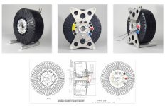
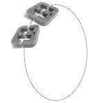
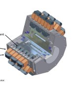
APL's DIY axial-flux motor

I would calculate if the pointy of your stator makes sense. It increases backemf as there is more circumvented flux, but does it outweigh the extra wiring length (resistance)? This can be calculated and optimised !

Also, the prupose of the stator metal is to reduce wiring length. The metal takes the permanent magnets flux and 'guides and compresses' it through a small metal area, which can then be wound around with a shorter bit of wire (as compared to unguided and uncompressed flux)
 
larsb said:
a tilted backiron slot would make it harder to wind well. I guess only benefit is lower weight?
another benefit is that i could move ballbearings inside of stator core so the width of the motor could be less. i don't know if it worth it..
 
It makes since to me to ramp, or cone, the back iron,.. you could keep the top part of the ramp flat, or parallel
with the tooth face, and just tilt the rear, for better windings? (Maybe thats the way it is, and I'm seeing it wrong.)
It's always a good idea to reduce weight, and having room for the bearing inside is a plus, and makes for a stronger
shaft and shorter case.

Problem is,.. machining or shaping lamination material. Man I hate that stuff! What a pain. :(

I don't know why it would follow any different rules than PM back iron though, which is quite a bit thinner,
except that the PM's are thinner as well. Which begs the question, how thin/short can the stator tooth be
made to be, and still get 1-1.5T flux without saturation?

If I get Lebowski right, in talking about the small end of the wedge, I've often wondered just how much use it
serves as well. That small section of at the bottom of the tooth can't possibly contribute much to the rotation?
I would think that the wedge shape should be more squarish in shape. But then theres a multitude of motors that
use the long and skinny tooth,.. so what do I know.

As said, the purpose of the stator tooth is to guide and compress the PM flux, and coil flux, into a small powerful area.
It also moves the strongest part of the coil 's flux, which is in the 'center' part of the coil, to the outside, or ends, where
it can be made useful.

But what happens with a really thin coreless coil?

I've often wondered if it's possible to make a coreless coil with the same, or close to same, amount of flux as a cored
coil? Say..maybe with a flat wound coil, or a foil core? If it could be made short enough...
(evidently not, or it would have been done by now)
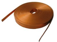
flatwire core.jpg

Another thought I had was to roll foil, or ribbon copper, and foil amorphous 'met glass' ribbon, 'together', in layers, to
form a highbred copper metal coil. :?: (like the inside of a capacitor, with foil and paper)
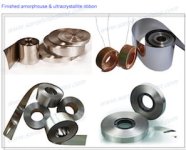
Amorphous ribbon..jpg

Just thinking out loud. :confused: (probably shouldn't do that)
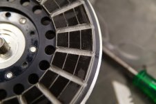
 
I don't know why you would machine back iron at an inconvenient angle. Lines will automagically detour to adjacent iron that isn't yet saturated. A problem that fixes itself, and perhaps not even a problem. Who cares if not evenly spread when less than saturated?
 
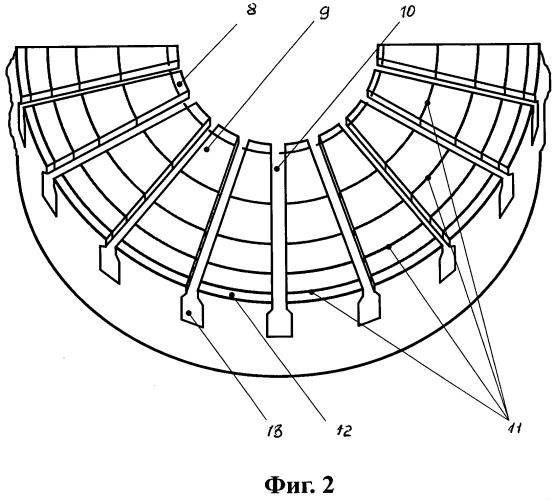
i'm not a kinda motor expert, i'm a rookie who learns every day. i've just red the patent issued in russia for the technology of making of axial flux stators. it is here: https://findpatent.ru/patent/265/2650104.html
it is in russian but i hope you can use google translator.
in short words, according to the patent's description the magnet flux in a simple wound axial flux stator goes easier in the parts of the teeth and yoke wich are closer to center of motor than parts which are closer to outer diameter. so that leads to uneven use of the core's steel, increasing of no-load currents and decreasing of the windings' insulation lifetime.
they suggested the core like this one:
11311406-o.jpg

as you can see the core consists of several coils with equal square of the front surface and with different width ( ? unfortunately i couldn't find the picture of back side). these coils made and wound separately, insulated between each other and press fitted each inside other.
 
APL said:
Problem is,.. machining or shaping lamination material. Man I hate that stuff! What a pain. :(

i'm with you, that's why i decided to buy wound coil and then try to make slots in it by edm machining. i shall keep you informed about my progress so you'd probably join the party..
 
I like where it's going, the stator iron should be honed down to a minimum for the work the motor will be doing.
In the end, form follows function, and in a perfected version, it would look quite organic,.. smooth and rounded.
To bad it can't be cast in a mold. :(

I was wondering if you can tell me how well the wound stator that you bought is bonded? Or what kind of glue or
epoxy did they use? Probably not, without wrecking it. Just curious. I think I'm going to buy a small one just to
experiment on. It occurred to me that one could possibly be disassembled, and the silicon steel could be cut or
rolled/used in different ways. And if it's really bonded well, then I can try cutting it, and see how that goes.

Small quantities of lamination material are hard to come by, although I've read that steel scrap yards in larger city's
often have lots. Something I have to look into yet.

No matter what I find to make cores out of,..laminations, metgals, somaloy, amorphous wire, soft magnetics,..all
are not available in small quantities. They want to sell pallet's of the stuff. :cry:
 
APL said:
I like where it's going, the stator iron should be honed down to a minimum for the work the motor will be doing.
In the end, form follows function, and in a perfected version, it would look quite organic,.. smooth and rounded.
To bad it can't be cast in a mold. :(
btw, i saw your experiments with composite core. your core was conductive because you didn't insulate particles of iron powder. i was digging around this before and found this description:

[youtube]QYFe0SAbvH0[/youtube]
i thought i could use some big plactic bottle and vacuum cleaner pump to build that kind of machine but then i switched for the steel wound stator so i dropped this idea. composite cores have twice less density than steel ones (as you already know) and they are also fragile and designed for relatively small torque values.

I was wondering if you can tell me how well the wound stator that you bought is bonded? Or what kind of glue or
epoxy did they use? Probably not, without wrecking it. Just curious. I think I'm going to buy a small one just to
experiment on. It occurred to me that one could possibly be disassembled, and the silicon steel could be cut or
rolled/used in different ways. And if it's really bonded well, then I can try cutting it, and see how that goes.
please have a look:

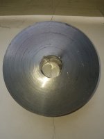
transformer core 2.jpg

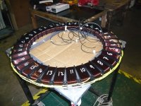
it is almost round shaped, i've checked the diameter with my fancy german caliper so the size deviation was not bigger than 0.5 mm. there is no epoxy or any glue. it is spot welded at the beginning and the end of the coil (2 spots at each end) and then annealed.

Small quantities of lamination material are hard to come by, although I've read that steel scrap yards in larger city's
often have lots. Something I have to look into yet.

No matter what I find to make cores out of,..laminations, metgals, somaloy, amorphous wire, soft magnetics,..all
are not available in small quantities. They want to sell pallet's of the stuff. :cry:
exactly. i found some sources with normal price but MOQ was one big coil which weights about 4-5 tons. finally i've bought it from china but that was damn hard to find. i have some connections in china so my friends helped me with that.
 
APL said:
One question I have is,.. I see in most all of the wiring arrangements that there is an interference point
between each set of phase coils,.. that is a north-north or south-south point on the back iron. Between 3-4,
6-7, 9-10, etc.

IMG_1983 copy.jpg

Seems really inefficient, as the fields are fighting each other there,.. like poles repel and all,.. :?:
So I'm going to assume that the phase rotation's diminish enough at that point, as to make it negligible?

Yes the fields are fighting each other at these points, but it should not have any meaningful effect on performance or eta since the magnetic field of the end turns is 90° twisted so it does not contribute to torque.

Lebowski said:
I would calculate if the pointy of your stator makes sense. It increases backemf as there is more circumvented flux, but does it outweigh the extra wiring length (resistance)? This can be calculated and optimised !

I was thinking the same thing.
And wouldn't the tip of the sator not go early in saturation?
If so then it anyway would not add that much to the motors torque so it probably would be better to have it not that "sharp" with the benefit of having lower copper losses.

I wonder why nobody is just going with a similar design as Yasa, Emrax, or Magnax for his own DIY motor (slot/pole count, shape of stator etc).
 
Thanks for the response on the fighting fields, I figured that it shouldn't be much of a problem, as virtually all
motors are made this way,.. but it bothers me anyway. :lol:
Another reason for why I like segmented stator teeth.

I'm thinking that the pointed tooth shape has to do with the size of the motor? Smaller motors need to take
advantage of all space, whereas larger motors can afford to have a more squared off trapezoid. :?:

As far as Yasa, Emrax, Magnax, designs go,.. they are usually quite large, and are inrunner designs. I haven't been
looking to closely at in-runner's, and it's usually a bit unclear as to how they are holding the coils/cores on those
designs. Usually lots of CNC machining. I'm sure it wouldn't be too hard to convert them to out runners though.

Most of my frustration comes from trying to figure out how to hold the coils, and still be able to easily take the
machine apart, and rewind/experiment with them. I'm not all that interested in permanent. (just me though)

They do appear to be using 16/18 18/16 etc. pole count ranges though, which is where this motor has been heading
for the same reason,.. that range is just right for efficiency reasons, and bike motors/controllers. (size)
The early Magnax design is very similar to what I'm trying to do, with segmented coils, but I can't find too many
pictures of the actual stator, or what they wound up with.

Early Magnax.jpg

But I do like the Emrax system :!: , It appears to rely, somewhat, on very well bonded coil's, which I don't like, for DYI,
as it's a bit too permanent. It's certainly the lightest way to go. :thumb:

Emerax coil holding system.jpg

Keep in mind, that these people all have patents, so making any motor that that resembles them too much, would
be taboo. :confused:
 
There is a massive amount of published research on axial flux motors. One of the more important design parameters regardless of the size of the motor is the ratio of the internal radius to external radius of the stator ring, that is Ri/Ro. A normalized plot of torque production shows a theoretical maximum at 1/ Sqr(3). Small variations around this figure are fine but given that the curve is an inverter parabola it is easy to visualize that significant movements to the left of right of the maximum have a significant negative impact on torque production. So yes drop the pointy ends of the stator. I would post a plot but I'm writing this from a hospital bed after a wipeout on my ebike has left me with 5 busted ribs and partially collapsed lung. Beware kids, ebikes can be dangerous. :oops:
 
Ah yes, I didn't look close enough. I see now that it's an outrunner, but mounted on one side. The more I look,
the more I like about this motor. They claim to have the best power to weight ratio, and I'm starting to believe it.

The Emrax mounting systam.jpg


And look, sectional PM's! :!:

Emrax rotor PM's.jpg

(Photos from; Emrax teardown;http://build-its-inprogress.blogspot.com/2017/05/emrax-motor-teardown.html)

Get well kiwifiat,..and try to keep the road part out in front! The only good thing I can see is that it's the end
of the season, so at least you not missing out on that. Best regards. :)
 
kiwifiat, i hope you will get well soon. take care.

APL, have you seen this video?

[youtube]E5VS4s-R7vk[/youtube]
 
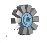
If you want a non permanent solution to mount your coils, maybe something like this could work?
motor idea  Part Studio 1 - Google Chrome.jpg

Just two metal rods going through the cores, and 2 screws at the end so they stay in place (I didn't drew the screws but I guess you get the idea).

It might slightly disturb the flux in the metal cores, but I guess this should be really minimal (but I'm no expert on this point so maybe someone who knows better could confirm it). Of course they'd need to be insulated from the cores so that they don't short the laminations, but this is probably easy to do, either dipping the rod in some epoxy to coat them, or just using heat shrink tubes.

This way you should be able to make all the experiments you want, just remove two screws and swap a new coil into place. Each coil could even have its own terminal connectors so that you wouldn't even need to solder them to test... But maybe I'm going a bit too far :wink:
 
Nice clean video damirsky, straight to the point, and shows all the different motor types in a straight up fashion. :thumb:

I didn't realize that the dual stator-single rotor had the advantage, except for weight. I'll have to give it more thought,
and consideration.

I like your concept Dui,ni shuo de dui, and indeed, I think that the motor should go in that direction. Central axle core,
and bolt down tooth. I hadn't thought about the through core idea, which would be a good solid way to do it!
So long as the windings could be parted for the rods/bolts, and the laminations could be punched/drilled. Perhaps a few
thin strips of non-ferrous material could surround the diameter to re-enforce. Just a thought. Wouldn't wan't to restrict
air flow.
Looks like a radial airplane engine, with lots of room for cooling. :)

A hollowed out hub, shaped like an I-beam would be nice as well, as the wiring takes up quite a bit of space.
Plug in cores would be awesome of course, and in my early thoughts, I had hoped to try that, but I'm not sure if a small,
and powerful enough connector exists, considering the amps involved. Sure would be nice though!

Much thanks for all the effort and thought you put in to your image! :thumb:
 
I anyone has LOTS of time on their hands, take a walk through these posts on 'Fieldlines', a wind power forum.

For some reason I'm infatuated with toroid stuff, and I found this generator build that uses a wound core in an odd
fashion.

A motor is a generator, and a generator is a motor,.. right?

So can this be made into a toothless, cogless, motor? I'm having a hard time figuring out whats doing what,
since it's all going sideways. :? It's not coreless,.buuuutttt....

Field lines build; https://www.fieldlines.com/index.php/topic,146642.0.html

Feildlines related;https://www.fieldlines.com/index.php/topic,145994.0.html

Does this have potential to make torque as a neodymium axial? The two rotors are N-N and S-S on each side.

L1010577.JPG
 
Yes, if it can work as a generator it can work as a motor. Not having any teeth will sacrifice some torque and efficiency but makes the core easier to build.

The dual stator single rotor has a lot going for it. For sure better heat dissipation. One option would be using “U” shaped cores that are made from off the shelf transformer cores. The rotor would need two rows of magnets with opposite polarities that line up with the cores. The rotor might not even need back iron but it would probably make construction easier.
 
Are you talking, coil at the bottom of the 'U' shape core, and rotor going in between the insides of the U?
Spacing could be tough, but construction would be easy, and it would have separated cores, which I like.
Light too, and no machining. Two problems, are tooth shape, and the motor would be larger.

Heres another thing I found about axial's today, 'cone shaped rotors'. I guess it gives more area to the PM's?
An interesting motor, on the Metglas site. It's an axial, leaning toward a radial.
Cone Motor;https://metglas.com/wp-content/uploads/2017/07/Metglas-Efficiency-Improvement-of-Tapered-Pole-Amorphous-Magnetic-Material-Machine.pdf

One thing nice about the toroid motor, is that the grain oriented steel is going in the right direction to be effective.
Up to 30 percent savings in that direction. Plus the fact that there is no machining. The N-N, S-S rotor poles are
squeezing the field through the core, and the PM's are crossing the wire at right angles.
But will there be enough torque produced in motor form without an actual tooth/air gap,.. I wonder. :?:
 
Sorry for the poor drawing:

transformer cores.jpg

The coil can be anywhere on the cores. Since one end of the core will be N and the other end will be S, you need two rows of magnets on the rotor. There may be more selection of "E" shaped cores, which could be done with 3 rows of magnets.

Not having teeth on the face of the core is a disadvantage. The main attraction here would be using already made transformer cores that are good quality material.

I suppose it might also work to turn the core 90 degrees so you can use a single row of magnets. This might be good for E shaped cores.

Another bad drawing:

E cores 2.jpg
 
Ah, I see now. It always amazes me, how a person can get a concept wrong without a picture. The first image is
nice, except I wonder if the bottom magnet will have a lower toque, having a smaller radius?

Putting the cores sideways, like in the second image would fix that. The only problem then, is getting the pole/slot
spacing right, and winding the coils in such a way as to even out the middle core's flux. On an E core, you would need
N-S-N. and the next would be S-N-S, as well?

But at any rate, E cores are plentiful, and would make a build really easy! :) It would be nice to be able to shorten
them up,.. as stator steel really adds up to most of the weight of a motor.

Coleasterling's image is how I had envisioned it, but makes for a very large diameter, specifically designed core's,
and excessive core material,(in my opinion). Adjusting air gaps is also a bit hard.

Unless person could make 'inserts' for the inside of the U-cores.

Cooling copper is excellent, and wiring is easier, so it's got good points as well. A beautiful motor!
Seems like there's no such thing as a perfect motor design. :(
 
Personally, on the new motor that I'm thinking about,.. I'm still wrestling with Dui, ni shuo de dui's idea
of using rods or bolts through the core. Except maybe just 'one' rod, and a saddle shaped hub on the bottom,
to keep the coils from twisting.

Whats nice about that design is that the rod keeps all the core faces perfectly aligned, vertical, and tied down
at the same time. On the Emrax, and on the motor I have now, they all have to be pre aligned, and can move
out of alignment at any time. Not good.

I don't like things going through the wires though, but maybe that won't be a problem, or we can figure out an
improvement, or a simular, or better way.

I would use a 'U' bolt over the top, but then were back to the 'shorted turn'.

That type of motor design system uses the absolute minimum amount of stator steel, and mounting hardware,
and would knock many pounds off the one I have now, and there wouldn't be any stator plates to make.
 
Back
Top