APL's DIY axial-flux motor

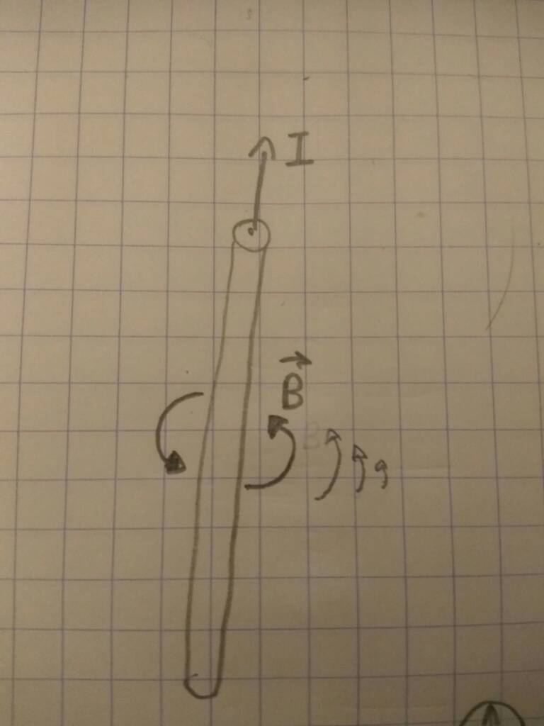
In a coreless motor the torque comes from the Lorentz force:

https://en.wikipedia.org/wiki/Lorentz_force

F = B * I * l

with B the magnetic field ( https://www.kjmagnetics.com/gap.calculator.asp ). For two round 25mm magnets, 7mm thick, grade N42, spaced 7 mm, no yoke, roughly 4000 gauss average. (or, 0.4 T, which is in he necessary SI units)

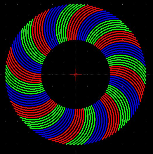
I, 50 windings per coil. Max force when magnets hovering over two neighbouring coils, so seeing 100 windings. At 20A -> I = 2000A

l, length, 25 mm magnets so lets say 0.02m average

-> F = 16 N (which is like 3 to 4 pounds in US units)

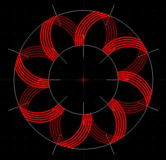
Then I got like 14 magnet pairs in V1, but all with varying degrees of pull (the 16N is peak). So lets say average pull is 8 N, times 14 so 110 N.
Then with magnet radius of lets say 0.07 m -> T = 7.8 Nm

At 1000 rpm this would be 780W mechanical power.

Another method to calculate would be to use magnetic field and rotor speed to calculate the derivative of magnetic flux. This then together with the 50 windings gives you generated voltage. Combined with current this gives you electrical power, which is the same as the delivered mechanical power. For losses, calculate your wire resistance (base on the length needed for 50 windings) and then use I^2*R
 
If you haven't already looked into 3d printing then I'd highly recommend it, incredible process and very useful but even more important imho, it gives a major change in perspective to anyone coming from a conventional engineering background. Many of those crazy "yeah, but how the hell am I going to make it??" ideas that come up when trying to find solutions suddenly become possible, needs a mental gear change to actually give them some consideration instead of stamping o them before they get out of hand ;) Less than $150 to get set up with including the filament, in hindsight a total no-brainer.

Really glad air core has come up, trying to understand it is causing me some mental gymnastics too so the brainstorming is very much appreciated! If it's any help, thinking in terms of the loop of wire (rather than the strand) seems to help fit in my head, kind of like the loop is a fan sucking on one side and blowing on the other. Probably totally the wrong way of looking at it but getting my head around a rotating field rather than a north and south pole is proving difficult :/

I think curving the windings with a slotted disk should get better infill and with deep slots it should be possible to get any depth of winding, something like this:
9JibOFLl.png


The front and back side of a single phase:
8MPIipsl.png


The logical next step from looking at those images is to keep adding depth of windings and it ends up more like a doughnut than a disk. I've been basing this on using field windings rather than permanent magnets btw but it's all speculation so far, seems like a big chunk of current could be passed to the field windings (ie. a small controller to drive a big motor) but I've nothing to back that up, really need to get a handle on field simulation software.
 
Hello ! Dark reader here ! I've been reading diy motor buildings threads for some time now and got interested in coreless design for my own build (maybe a thread opening soon). I see you're looking on it here too now, that's great :)

How I understand the torque generation in this design (flat toroïdal coil or faulhaber coil) is the same as what Lebowsi said earlier, from laplace's Law a current flowing in a strand of wire in a magnetic field produce a force perpendicularly to the direction of the wire.

Stan.distortion what gain would you expect from a curved winding ?
How I see it is that the closest it is to radial direction the more the force contribute to usefull torque. So the inscrease in infill may not be beneficial, since the more torque producing part (outer radius) is the less radial one.
It definitely need some integral calculus :)

Envoyé de mon Redmi Note 3 en utilisant Tapatalk


Thanks Lebowski, for the explanation of Lorentz force, and calculations to drive at torque/watts. It's just what I need.
I need to chew on that for a while, to get a true understanding, and be able to use it, as it will be one of the MOST
useful tools to have when calculating motor ideas. :thumb:

All these motors use the Lorentz force between wire and magnetism, the three finger rule so to speak, but is it more
advantageous to use the concentrated form of a coil, or spread it out over the wound stator, like stan.distortion
has just drawn? The continuous wound stator seems to have much more area, but no concentration, and has to be
wound in a series ABC,ABC fashion. Where as the coil can be individually enlarged or shaped, and can be wired in
AaBb,BB,cc,etc configurations. (Which may or may not be an advantage) Six of one, half dozen of the other?

Stan.distortion, your right about 3D printing, the cost has come down for those machines to where they are affordable
now, and even if a cheap one can't do some things, it is an easy entry into the how to's and basics, and understanding of
what is obviously the future of things to come. At any rate, it's perfect for little parts, brackets, or connectors as well.

I've also seen your style motor divided up into three large separate sets of windings, three tooth? And have wondered if
that would have an advantage. More torque, slower speed, more unbalance? I don't know, just a thought.

Adding more layers of windings will slow the motor down I would think, but I'm not sure about adding torque, I think
maybe not, but it will probably make cooling a bit harder, which wouldn't be good. Just a guess.
 
Fechter, I was thinking that it might be a good idea to take another look at the single rotor motor style for a model,
and put the rotor back on the inside. Since two sets of rotor magnets don't add up to twice the Tesla force, and
the central mono-rotor magnets can be as thick as needed. It also makes since to have the air core coils on the
outside where they can be cooled and mounted more easily. Double coils might be more easily tweek'd for wire
size's and might make the motor lower RPM, for bike use? (Maybe even two rotating steel back irons? Or not)

The drawback is that it will have to be an an inrunner, unless some fancy axle work can be figured out.

Heres a video of a DYI axial that has lots of power. I can't believe he made it out of wood! But there it is,.. works good
too! It is a bit LARGE!! And I'm not quite sure why he has a gazillion windings on a 40v motor, but it's worth a look. :bolt:

Youtube video; https://www.youtube.com/watch?v=3BHhj9M_UX0
 
I think that as you said using a single rotor on the inside make sence for lowering the magnet mass without massive torque losses, but it also mean the use or a back-iron on either side or as you said rotating Steel disk to close the magnetic circuit.
If the rotating disc have some slot milled-out maybe it can had more torque making it some sort of hybrid switch-reluctance motor ?
Another track to follow maibe

Envoyé de mon Redmi Note 3 en utilisant Tapatalk

 
Just to be clear as to what I was just saying about a single central rotor motor, I'll use damirskis picture
(hope you don't mind damirski, it's an awesome pic. :) )

Damirski motor..jpg

Air coils instead of laminations. But then there should be some back iron on the back side of the coils? Too bad.
Always something! More weight, more complicated. And if the iron isn't rotating with the rotor, it will be subject
to eddy currents again. Right?

Outside rotating back iron rotors really makes a mess out of the design, although, it would be an opportunity to use
them as fans, to cool the air cores.

Thanks for your input, Thecoco974,.. I'm not sure about the switch-reluctance part, thats a little beyond me at the
moment, I'm still working on the simple stuff. :)
But perhaps you are right, and in addition to cooling, they could be made to produce a stronger field somehow,
by milling a coil shape of some sort into them. :idea:

As an added note, theres also this kind of winding, one of three, that overlap for the three phases. It could
possibly replace the wedge air cores, and be somewhat lower profile, and stronger? Just tossing ideas around.

Overlap winding..jpg

I think this new, single rotor, direction I suggested is staring to fall apart with complications,.. but it needed to be said,
we will leave no corners unswept!

Maybe if the back iron idea is just scraped, and go back to simple air cores on each side of the rotor, it can be salvaged.
 
Heres another visit to the 'concentrated coil' idea thats been swirling around in my head for awhile. Still a pot
of soup, so to speak, but I've got enough to at least convey the concept.

The idea is a coil thats halfway in-between a laminated core and a coreless coil. Sort of a way to enhance an
air core motor, and bump it just enough into being more usable for bikes. IE, more torque.

The 'perfect' version would use several, or dozens, of Metglas type ribbon layers, stacked in between copper strips,
and rolled into shapes. Several copper strips would be soldered together, just like multi strand wire.
But that amorphous ribbon is not cheap, and I don't have much access to it.

Concentrated Staor coil..jpg

So the DYI version is to use multi strand wire, and some sort of electrical steel, rolled together. The crappy coil I
made is just to demonstrate. I know the laminations are going the wrong way. The stacked silicon steel wire idea
would solve that, but adds lots of labor. Still , it would be unidirectional.

Hybrid concept.jpg

Hybird Concept 2.jpg

One advantage here is that all copper is in contact with all steel, not possible with steel cores.
So, a smaller, concentrated unit.

Crazy stuff. OK, beat me up Scotty! :D What think?
 
Thecoco974 said:
...
Stan.distortion what gain would you expect from a curved winding ?
How I see it is that the closest it is to radial direction the more the force contribute to usefull torque. So the inscrease in infill may not be beneficial, since the more torque producing part (outer radius) is the less radial one.
It definitely need some integral calculus :)
...

Initially the aim was to provide support for the windings while keeping them exposed to the air for cooling. There could be a lot of movement in exposed windings and encapsulating would hurt cooling so slots seemed to make sense, trouble is the minimum wall thickness for regular 3d printers is about 0.5mm so the walls of the slots could easily add up to half the available surface. Curving the windings seemed a viable way of getting some of that back, putting more copper in the space lost towards the circumference with straight windings. Makes sense that the windings need to be as near as possible to radial though, my thinking was at an angle the forces would be weaker but last longer. I'm still not really clear on it but everything I've read suggests that isn't the case, that they will simply be fighting against themselves and killing efficiency.

APL said:
...
Stan.distortion, your right about 3D printing, the cost has come down for those machines to where they are affordable
now, and even if a cheap one can't do some things, it is an easy entry into the how to's and basics, and understanding of
what is obviously the future of things to come. At any rate, it's perfect for little parts, brackets, or connectors as well.

I've also seen your style motor divided up into three large separate sets of windings, three tooth? And have wondered if
that would have an advantage. More torque, slower speed, more unbalance? I don't know, just a thought.

Adding more layers of windings will slow the motor down I would think, but I'm not sure about adding torque, I think
maybe not, but it will probably make cooling a bit harder, which wouldn't be good. Just a guess.

I've been totally blown away by how capable the cheap 3d printers are, plenty accurate enough for things like ball bearing carriers (pillow blocks) and toothed belt pulleys. Takes some getting used to though, the layers are the weak direction so it's kind of like working with wood but with the grain in a single dimension and ABS can be tricky to work with (needs a heated enclosure to do right imho). PLA is more common and its amazing stuff (plastic made from corn starch), very rigid and easy to work with but totally useless for high temperatures, a cup of coffee is plenty hot enough to soften it.

When you say 3 large separate sets of windings, do you mean like the above diagram but with 1/3rd red, 1/3rd blue, 1/3rd green (ie, 120 degrees apart)? I'd have thought that would be for a high rpm motor but that's only really dependant on maximum switching frequencies (found that out the hard way with VESC controllers). My thinking at the mo is damn thick windings and more of 'em equals more torque but I've no doubt that's vastly oversimplifying it, my background is hydraulics and it's pretty much the same when it comes to simple electronic circuits but it seems to be getting in the way with electromagnetism :/
 
Lebowski, I would think that the steel in this kind of core would concentrate the flux, at least a little more, than without it?
But since the air cores are so thin, or short, it may be unnecessary,.. that's true.

Theres also the fact that most of a coils flux is in the center of a coil, between the ends, and the steel moves it out farther
to a solid point, or plane, closer to the PM's surface. But again, a coreless coil is pretty much saturated, or pinched in the
flux gap. So, again, it may be that the steel in this coil type is just going to get in the way.

Coil flux is very low on the ends.
Magnetic flux density in a coil core.png

Just tossing the idea out there, so please, by all means, tear it apart. I'm sure I'm missing something somewhere,.. it's just
that I've never seen the idea anywhere in all my searches. Also, I'm only looking for a small percentage of improvement.

Stan.distortion, yes three separate sections, each = one phase. And your right, it should be a faster turning motor, like
WAY faster! Unless I'm missing something again. I couldn't find the photo,.. too many searches. :cry:

My father always used fluids to explain electronics to me, and it works quite well for a lot of things, but falls apart with
some others. I think I've seen simi-equivelent systems called fluidics? Clock's and circuits and such.
(Maybe that 'is' hydraulics)
Works well with wires, but things like magnetism, static charges, radiation, or microwaves, are hard to relate to fluids.

Heres yet another way to build an axial I haven't seen before, the idea of using central magnets is attractive because the
shape and size of the PM's isn't quite so important as on a rotor, and they can be centrally located and concentrated.
Hmmm, need to give this some thought. :idea: The actual mechanics of it is probably worse though.

Extended Magnet plates..png

And another one like it; https://www.cgen.eng.ed.ac.uk/sites/cgen.eng.ed.ac.uk/files/images/C-GEN%20Technology.jpg
 
Yes, and I suppose it would be hard to make it light enough too. I see that they stop short of covering the outer
part of the coils with the rotor, which contribute very little to rotation,.. I assume that's on purpose.
Interesting though, I wouldn't have thought of that. Also shortens the flux travel distance from the magnets.

I wonder if a modified rotor would be possible, and take the idea a little farther, by reducing all excess metal.
Fingers, could maybe work for cooling as well?
Excuse my 'pencil cad' drawing,..( quick and dirty. :)) 'Something' like this.

Lightened Rotor..jpg

If the rotors are stacked, then the gaps can be adjusted.
Another problem with this design is that the coils are harder to mount, or hold, and need to be done from the
outer radius, making the motor diameter large as compared to the rotor. Also, I think it has to be an inrunner.
 
What of repulsion instead of attraction? Drive high frequency AC to a sequence of coils to repel plates or rings in an otherwise insulating rotor. You've already some experience how much force eddies can create. Or perhaps a good old squirrel cage with variable frequency drive could somehow be turned axial?
 
That last picture is pretty interesting. I wonder what material they use to enclose the coils?

With an iron core, it takes much less (current x turns) to get a given flux compared to no core. Flux translates to torque. So to get the same power, you need higher rpm and more gear reduction. More turns helps, but space is really limited for copper. There are always trade-offs in design. So for a good coreless motor, plan on a fairly high rpm and needing more gear reduction.

KD5ZXG said:
Or perhaps a good old squirrel cage with variable frequency drive could somehow be turned axial?
This is certainly possible if you don't want to use magnets. It takes a different controller. Tesla motors use induction and have good power density and efficiency. I'm not sure I've ever seen a coreless induction motor.
 
I would have included the source for the last photo, but the site wouldn't download for some reason. So after a bit
more searching, I found a different source.

Multi rotor design; https://www.semanticscholar.org/paper/On-the-feasibility-of-carbon-nanotube-windings-for-Rallabandi-Taran/d01f622ba7a17a0ba8afb776373f80a51254e833

It doesn't appear to be an actual motor, more or less talking about nanotube tech of some sort, but you can see the
purposed coil holding design, which doesn't make a whole lot of sense to me.

I had the thought of maybe reversing the design, and putting the coils on the inside, and the PM's where the coils are now,
for an out runner. But haven't worked it out yet. The fingers, or what the rotor is now, would have to be Si. iron though.

A picture from the last link of a similar set up, looks like printed circuit style coils?;

Multi rotor axial..png
 
I guess I've always looked at the purpose of the core from a different angle. That it's 'main' purpose was to bring the inner
coil flux out to the ends of the coil, where it can do hard work, and that the shorter wire, and resulting resistance, plus
better cooling, were just a byproduct of that. An extra. Just as hysteresis, and the resultant heat, along with weight, are
also extras.

In the concept coils above, I'm adding iron to the air coil, making it more concentrated, and focused, bringing more flux
out to the PM. The wire in the coil is mostly in direct contact with metal, making cooling, or heat transfer better, and the
wire length is shortened, as compared with a standard air core coil.

How is all of this 'not' an improvement?
 
Just my take on motors... i look at them as voltage generators. Motor power comes from volt and current, so the motor should make as much volts as possible and conduct current as efficiently as possible. For me thinking in terms of electromagnets is not where its at...
 
KD5ZXG, I'm having trouble understanding what you said,..are you talking about something that uses aluminum rings that
are repulsed from a Tesla coil type of concept? Or perhaps an aluminum disc with holes that is induction run, much like
a power meter on a house? Don't mean any disrespect, just trying to understand.
 
Whats been bothering me about coreless coils, is the amount of wasted space in the shape. The end windings on top
of the trapezoid are useless, and can use almost one third the length of wire. The small amount on the bottom is better,
but still rather useless. The hole in the center is just plain wasted space, and has no value.

Coreless stator DIY1.jpg

I'm speaking in terms of Lorentz force, which I assume is the only force at work here?

But on the flat disc shape stator that Stan.distortion has drawn above, and others here are using, a much wider radial
space is available, and there is little if any waste. All of the radial wires are available for Lorentz force to work on.
The PM's can go all the way out to the edge of the diameter, and the inside radius is only limited by the wire thickness,
plus, the stator is much stronger, and simpler, being made of one piece of glass board, allowing the PM's to be close to
the wire on both sides.
The flux in the gap might have the advantage of being stronger, because the stator can be made thin.

There are a lot more coil segments leading to a smoother motor, and a slower spin. And the design lends itself better
to Halbach Arrays.

Personally, I still like the straight wound toroid style.

Toroid wind..jpg

But heres the thing, what am I missing? Is there some other force present with the Trapezoid coil? A concentrated center?
Maybe it's the fact that you can wind much more wire in one coil. Wouldn't a lot more segments have the same effect?

A comparison of the areas of two single coils,.. the first coil has very little 'actual' space for the magnets to work with. (A)
As compared to the wider area on the second coil. (B)

Relative areas.jpg

(This stuff keeps me awake at night :( )
 
https://en.wikipedia.org/wiki/Electrodynamic_suspension

APL said:
KD5ZXG, I'm having trouble understanding what you said,..are you talking about something that uses aluminum rings that
are repulsed from a Tesla coil type of concept? Or perhaps an aluminum disc with holes that is induction run, much like
a power meter on a house? Don't mean any disrespect, just trying to understand.

Yeah, rings embedded in an insulating rotor repelled from high frequency coils. Higher frequency than rotation for efficient repulsion, but with modulated intensity that rotates in much the normal slow way. Except pushing rather than pulling.

Iron might help or hurt? With frequency increase maybe forced to powders or ferrite at lower flux and torque. Still more than air. Tesla might be overkill frequency, making iron impossibly lossy. Something less than RF, yet more than audio.

Iron (and ferrite and any other permeable) adds inductance which makes difficult to conduct high frequency AC current. Though shorting rings lower that same inductance as they pass, so maybe it still works?

Aluminum disk with radial slots would tend to position slots over
an active induction coil. My first thought was holes too, but current would just run around them. Have to cut every eddy but the ones you want repelled. And that dumbs down to rings in an insulator.

My whole suggestion is very less than half baked, so don't take it like you misunderstood anything.
 
How I understand it is that there is two ways of looking at how the torque is produce, one way is using the Laplace forces (Lorentz same thing) as Lebowski said. The torque is at his max when a magnetic field is crosing the more activ turns in wich current is flowing in the same direction, so when the magnet is in front of one side of the coil.
Another way is by saying that the maximum torque is produce when the magnetic field of the magnets is 90° out of phase of the coils field, the maximum of this field is located in between an activ strand and his return, looking at it like this makes the max torque happening at the same moment as the other methode so it make sense to me :)
I visualise magnetic field created by one wire like this:
c5e29bfc9fad5d8ac4b6ac103459e4d5.jpg


The magnitude of the field decrease with distance. And the field of two wire going the same way addup and oposing substract. So for a flat toroïdal coreless coil you can expect the field of one side and is oposite (since if the current is going the other way the field rotate the other way as well ) to addup and look something like this :
IMG_20190919_235335.jpg
It's a cross section of a toroide stator laid flat. The point means the current is going out and a cross means going in the paper. Not sure it's understandable nor right but this is how I see those things work :)

Envoyé de mon Redmi Note 3 en utilisant Tapatalk

 
Yeah, rings embedded in an insulating rotor repelled from high frequency coils. Higher frequency than rotation for efficient repulsion, but with modulated intensity that rotates in much the normal slow way. Except pushing rather than pulling.

Starting to sound like a squirel cage induction machine...
 
Awesome KD5ZXG, I like thinking out of the box! Only problem is, now I have a hundred more searches to do! :lol:

Let's see, theres the AC induction disc motor, or Arago's rotation, which is related to Faradays Homopolar motor,
which I'd love to revisit, because I think it's been overlooked, and we might as well throw in the Lorentz rail motor,
for lack of a better term, related to the rail gun. Along with your high frequency ring idea.
Should take about a year, but all of it needs a good looking into. :)

Induction-disc-AC.jpg

homopolar-generator-model-B-field.png

Lorentz rail motor.gif
 
Thanks for the explanation Thecoco974, looks good, I can see how the torque is greatest when trying to get from
one coil to the next. The magnet wants to sit directly over one coil with an opposite pole, and when the voltage is
reversed, it gets pushed from one coil, and pulled from the other. In between, the torque is strongest.
I wonder 'exactly' where the voltage is switched? Slightly after that point, or dead center of the coil?

This allows me to reiterate what I was saying earlier, that the PM magnets have to be situated directly across from each
other, N and S. This means that one side of the windings coming up, must be directly across from the corresponding
wires going down. The N and S sides of the coil.

In many of the motors I have been seeing, it appears as though they are skewed somewhat, so that the magnets would
have to be shifted, and won't work very well. Unless they are skewed all the way to the next pole,.. which is quite a ways
away.

So, either I'm not seeing it right, or I'm missing something. Probably both.

Prallel and sqewed torque.jpg

Sorry to beat it to death, but these things bother me. The windings should be straight up and straight down on both
sides, like the toroid photo above.
 
Back
Top