RadPowerBike RadCity Commuter

tomjasz said:
I'm confused by your question... it's an o-ring using friction to hold the throttle position. Works great on MC's and Scooters. I never use twist throttles so I can't speak to the fit on eBike throttles. I had the style pictured. I assumed it was aboutreducing hand stress to maintain a steady speed. Did I misread?
The throttle sub-discussion is about converting grip throttles to thumb throttles, without changing the throttle unit itself. (not about any form of cruise control, mechanical or otherwise, which is what the o-ring does)

For an example of what is being discussed, see my first reply to Alan B about that, with the images and the link to the aliexpress page I got them from. ;)
 
Alan B said:
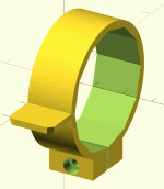
Here's the basic idea, a ring with a tab that fits around the twist throttle.

thumbThrottleAdapter.GIF
If you leave the ring open, and make it slightly smaller than the grip part of the throttle, then it'll do what the one I linked does, and fit many different models. If the opening is on the side of the tab toward the direction of movement, then pressing on the tab causes the ring to grip the throttle. If necessary you could add little axial ridges on the inner circumference of the ring to help it grab, but the one I linked to (which I have here) is perfectly smooth and shiny inside.
 
amberwolf said:
Alan B said:
Here's the basic idea, a ring with a tab that fits around the twist throttle.

thumbThrottleAdapter.GIF
If you leave the ring open, and make it slightly smaller than the grip part of the throttle, then it'll do what the one I linked does, and fit many different models. If the opening is on the side of the tab toward the direction of movement, then pressing on the tab causes the ring to grip the throttle. If necessary you could add little axial ridges on the inner circumference of the ring to help it grab, but the one I linked to (which I have here) is perfectly smooth and shiny inside.

Good suggestions. My quick drawing is just a few lines of OpenSCAD. It is not scaled properly yet, and needs some way to tighten on to the grip, as you indicate.
 
Regarding flats, there are a few solutions.

I used to use Slime / etc and it worked alright in most situations...but when it didn't work, it made it next to impossible to patch the tube on the side of the road unless I also brought stuff to clean up the mess.

I still carry a little bottle of it on the trike for situations where I just am not going to be able to stop and patch the tire or replace the tube, if something gets past the barriers below, but I don't usually put it in until I already have a flat (which is very very rare nowadays, despite the amount of pointy crap on the roads, including mesquite thorns an inch or more long).


So nowadays on bicycle tires I use a layered approach, since the motor power effectively negates the extra rolling resistance. From the outside (road) to the inside (rim):
--actual tire on the road
then
--slime (or other brand) protective strip
then either:
--old (slick) tire with the bead cut off
or
--old thick innertube(s) slit along the inner circumference, valve stem removed
then
--actual (thick) innertube
then
--rim tape (velox, etc)

As many old slit innertubes can be used as needed to provide the thickness necessary to prevent the longest stuff you've got to deal with from getting thru.


So far just as effective has been to use moped tires and thick moped tubes, on my trike's "20"" rear wheels (makes them effectively about 22" instead, using 16" Shinko moped tires), though I am also now using one slit innertube on those, too.
 
Just for fun, here's the OpenSCAD that made that quick thumb throttle adapter. Values in mm. It is basically a cylinder and a cube, with a cylinder subtracted from it to make the hole. Super simple.

Code:
// thumb throttle adapter  9/2019  akbiocca

rotate([90,0,0])  // stand it up for viewing (disable for printing)
{
    translate([25/2-1,-1,0])
    cube([10,2,10]);  // thumb paddle
    
    difference()
    {
        cylinder(d=25,h=10);  // outer diameter
        cylinder(d=20,h=10);  // hole for grip
    }
}
 
Long day working on the RadCity.

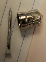
Fixed the rear flat. A small 1" long nail. Installed a very thick tube in the rear tire. Set it to 40 psi. I may patch the removed tube for a front spare. I think in the rear a thick tube is worthwhile. Probably not in the front where flats are rare.

To remove the rear wheel required cutting one cable tie. The connector unplugged nicely, just 3 pins, so it must be a sensorless controller.

The derailleur guard was damaged in shipment. It is bent inwards toward the bike so it needs to be replaced to allow full motion and provide useful protection. The shifting / chain tension don't seem to be quite correct. I didn't work on it, but it does need some attention. Perhaps the crash guard wasn't quite enough to protect it during shipment.

Most of the effort was on the front wheel. Even after two passes of tightening 1/4 turn per spoke they were still loose. My friend has a fancy Park Tool trueing stand, a spoke tensiometer and lots of wheel building training and experience. Many iterations of small spoke adjustments were made - lateral, radial, tensioning and equalizing adjacent "married" spoke pairs (single cross wheel) as well as checking the dishing (sorry if I don't have the terminology straight). The wheel was not too bad to start with laterally but the spoke tension was way too low. The measured spoke tensions were 2-3x lower than the low end of the recommended range for these spokes according to the Park charts. It was so loose the spoke ends were popping with slight motions of the spokes and they would rattle when riding the bike even with a light rider. By the time it was done there were at least 2 turns tighter on every spoke (in passes of 1/4 turn), and even then it was a little shy of the recommended tension. But it is much, much better than it was. No popping or rattling noise now. We decided to ride it this way for awhile and recheck them later.

I adjusted the brakes and allowed a little slack in the cable so the adjusters could be used to optimize the brakes with a little space before they came on. As delivered the brakes were too snug and there was no slack to give the levers to allow regen before friction braking. Regen develops right around 285 watts according to the onboard display.

This seems to be a power throttle. Nice feel, but well filtered and lots of delay. The motor runs silently, so this tends to confirm the control is sinewave. None of the resonances that you get with trapezoidal waveforms were present.

The PAS levels seem to be discrete power values. We'll have to get more accurate numbers for these but PAS 1 was about 80 watts, and 4 and 5 were 500 and 750. But there are distinct steps in power.

Max power does seem to be 750W peak input power. Due to the filtering/delay it feels like even less. Of course the output power is probably less due to system efficiency. Some ebikes seem to use average output power rather than peak input power, which improves hill climbing and acceleration by 25-100% depending on the circumstances (and draws the battery down quicker as well). When this is done the input power measurements will temporarily exceed 750W but then drop back as the speed comes up.

The cute little torque arm is not very tightly fitted to the flats on the axle. It wobbles back and forth quite a lot before engaging the flats. There are also two torque washers - one per side. I don't know if those are actually useful, but this setup is pretty mild which helps avoid the torque peaks that might be problematic. If the power is increased a better fitting torque arm would be advisable.
 
throttleAdapter20190917_094958.jpg


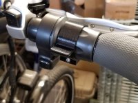
This is the first prototype, still warm off the 3D printer. It actually works as-is without a screw. After taking the photo I put an M3x12 screw in and let it self-tap as it was turned in and that fit fine. The internal flats really grab onto the ridges on the half twist and keep it from slipping, even without a clamp screw.

I don't have feedback from my son yet but this looks good enough to use.
 
If it's designed to mount only one way, I'd recommend making the side your thumb isn't on a "ramp" instead of "vertical" on both sides.

This will make it much less likely to snap off at the root (which is how every thumb throttle I've ever broken has failed, usually while I'm at full throttle while accelerating and then hit a bump or pothole).
 
That is an excellent suggestion. I did consider doing that but was lazy and didn't do it, however if it does break I will do exactly that.

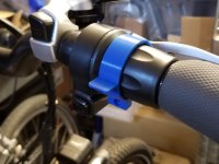
I just tested the blue thumb throttle adapter I removed. I can't break it with my thumb, though it is flexing some. At least with anything like reasonable force. Unlike a traditional thumb throttle, this paddle has full support across the width, instead of just a little strut in the middle. Also when fully depressed it is pointing well downward so a vertical impulse would tend to slide along it rather than break it.

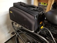
I'm working on a Topeak slide mount for his trunk bag. That has a locking slot in the front that the bag slides into. I'm going to beef that up for as the trunk sliding forward into the tab sticking up will have plenty of momentum to damage things. It is important to think about the stresses in these designs.

Unfortunately I don't have a printer large enough to print the mount for the Topeak in one piece. So I will have to split it into a couple of pieces. I can only print to about 220mm in each dimension right now. Larger printers can be purchased or built but the cost goes up, the space they take goes up, and the materials and time to print on a large printer goes up fast. It can take days to print something large.
 
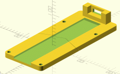
This design is pretty much done. It fits the Topeak MTX rack bags that slide into the dovetail and lock into the forward tower. Set up for 5mm capscrews into the threaded holes in the RadCity rear rack and cut in two for printing on a Prusa MK3 printer. I've updated this posting with the newer design, this is hopefully final.


topeakMount.GIF
 
Alan B said:
Also when fully depressed it is pointing well downward so a vertical impulse would tend to slide along it rather than break it.
All the ones I broke were pretty well like that too, but they still broke....

The tabs on all of the throttles I have broken are the oval contoured type, sort of like a propeller blade, with a similarly sligthly fluted base, however the base is very sharp-edged transition to the throttle ring. Some of them break there, some of them break above that at the thinnest part of the "fluting", one broke in a "shard" pattern starting at that transition up thru the fluting and into the tab itself.

All of them would probably still be intact if they had that "ramp" and a smooth curving transition to the ring on all sides instead of a sharp one.
 
Adding the support behind the tab moves the stress concentration point further out. That should help. Of course if we make it strong enough it might break your thumb... We can always print another if necessary. In this case it is a half twist throttle so if the tab breaks the throttle still can be used. And this bike has fairly good PAS so an inconvenient or even broken throttle isn't really a show stopper.

I printed a couple of test slices of the Topeak MTX Rack Adapter to verify the fit, made a couple of adjustments and am now starting the print of the forward half. That will be nearly six hours of printing, even in 0.30mm layer "draft" mode.
 
The four rack mounting holes aren't quite square, things don't fit as nicely in hardware as they do in software. :)

The slightly wider dovetails do fit better. The test slice was loose so I tightened up a bit, turned out to be too much. The two halves need better alignment, and more compliance for minor errors in the rack's fabrication. Have to come up with a better way to split the parts.
 
Interesting. Do you think a 3D printer is a useful tool or is it more of a hobby and you have to actively look for projects that you can use it for? I can think of a couple of times in the past year it might have been handy to have one, but I was able to find another solution.
 
I had the same question for a long time. I didn't expect that 3D printed plastic would be strong enough to be all that useful. That turns out to be wrong. It is accurate enough and strong enough for most things. I've seen people print shelf brackets for books, it can be strong enough for a lot of projects if used properly.

I bought the 3D printer for a particular part I wanted to make. Now I use it several times per week, and many things it makes would be very difficult to make otherwise. For example parts with curved internal tracks for cable ties or wires - no way to mill those. 3D printers are the easiest CNC machine to learn and the easiest to have around - clean, quiet, low power, and if the right filaments are used nearly odor free. PLA has a mild odor like French Toast when it is melted, and I use that most of the time. I've made several dozens of designs with 3D printing, and printed a few things from the web as well. There are more than two million internet designs indexed on yeggi alone to print, or to use as ideas or even components in your own design.

I'd still like to have a CNC mill for aluminum and steel but if plastic will do the job the 3D printer is a great way to do it, and for ten times less investment. If you like to make things it is a great tool. They have come down a lot in price, if you are handy you can get something that works for a couple hundred bucks.

I 3d print a lot of jigs, adapters, holders, and tools with my 3D printers. Customized funnels, trays, reels, adapters, covers, boxes, struts, signs, name badges, hooks, protective enclosures, brackets, etc.

I didn't have one when I built my eBikes, but I've made a number of things recently for upgrades. The thumb throttle adapter and rack adapter in this thread and the mounts for the battery in the Peugeot Canyon Express thread. A dual Cycle Analyst bracket in the Bonanza thread. Some of these things would be easy to fabricate with aluminum, others not so easy. Making 3D parts is amazingly easy if you have a design file - choose a filament, load it up, and start the printer. Unlike fabricating a complex part that might take a lot of time and tools in the shop, the 3D printer once started requires pretty much no input. There's very little mess to clean up.

It really helps if you are interested in learning (or already know) how to design things in the computer. Then you can design that widget that does precisely what you want. Make some measurements, make a CAD model, print a prototype, and try it. Even if you are going to machine aluminum or steel for the final product starting with a 3D printed model is a great way to see that it fits before cutting metal. I recall the first 3D printers I saw years ago were about $30,000 and the mechanical engineers were using them for conceptual prototypes to sell their ideas and show how they worked and fit together. It is also great for some of those little things the wife wants. I've made enough things for the wife there are zero complaints about 3D printing expenditures, except maybe about what I'm going to do with that old 3D printer now that the new one is up and running. :)
 
My "old" printer is a Lulzbot Mini. It works fine, in fact I put new upgrades on it recently. It is now upgraded with many of the features of the newer model that you will find on their website today, like a removable printbed. The main limitation of the mini for me is the print volume - it is about a six inch cube. I bought it in early 2018. My newer printer has a bit larger print volume, about 8" cubed. Many things fit in the 6" cubed print volume, but some require more space. Even 8" is not big enough for everything but it is a compromise.
 
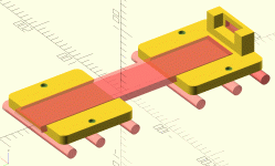
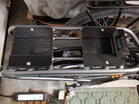
Refining the Topeak MTX RadCity Rack Adapter design to accomodate the 2mm shifted mounting hole and reorganizing it to sit on the support bars in two sections each long enough to span three bars for stability. This shifts the trunk a little to the rear and away from the seat but still within the fairly long RadCity rack. Started another print. The front piece fits, waiting for the rear. Son works tomorrow, trying to get it up and running for his commute.


topeakMount.GIF
 
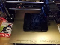
Very strange, the second half is printing with a major problem - the top and bottom surfaces are missing. I've never seen that happen before, some kind of bug in the slicer. I'm tempted to let it finish as it won't take long now and it might actually work anyway, at least for a fit test and for temporary use.

Skipping the top and bottom surface makes the printing MUCH faster. Might be useful to do for some tests. I'm not certain how to cause that to happen though. Must be a switch for that in the slicer, though in this case I didn't make any changes other than reloading the model and splitting / deleting the other part to get it to slice correctly.


20190920_182624.jpg
 
Back
Top