
You are using an out of date browser. It may not display this or other websites correctly.
You should upgrade or use an alternative browser.
You should upgrade or use an alternative browser.
APL's DIY axial-flux motor
- Thread starter APL
- Start date

Thecoco974
10 W
- Joined
- Dec 7, 2016
- Messages
- 94
Sorry, my explanations are not the best ! When looking at max torque production, the magnetic field of the magnet and the magnetic field of the coil should be 90° as shown here with a very large airgap :
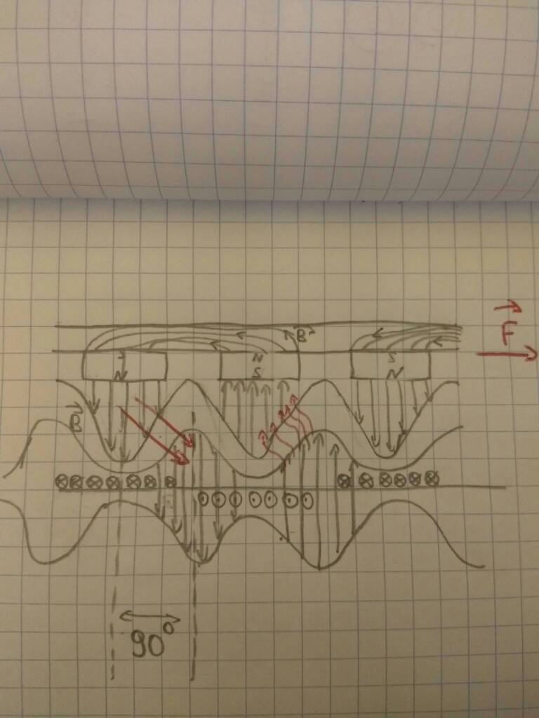
We can see that when in this position the magnets field will want toconnect the coil one at an angle, this is what produces a forces that translate to torque. When thé magnetic fields of the two are in Sync we Can see that all the force is axial so no torque production. The controler is trying to Always keep this 90° out of phase to produce max torque. The other two phases are here to make that possible.
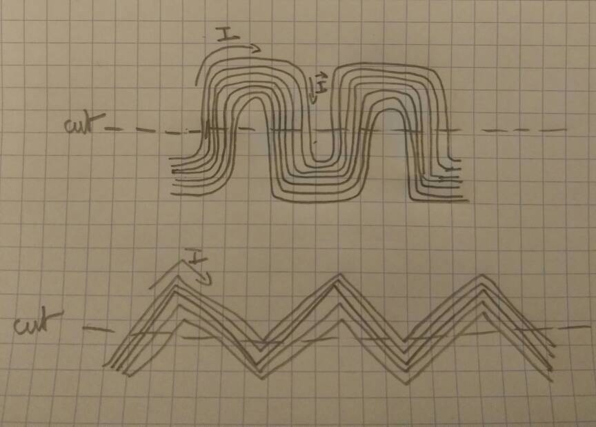
The cut wire that I am drawing are from a serpentine coil or as you said a "skewed" one, it's actually pretty similar, it's just a way to eliminate the wasted copper on each end of the coil but it means less torque since it's not in the radial direction, it's a compromise to look at between resistance and torque.
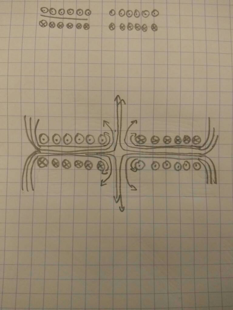
The simple coil you're talking about is not the same story, we can't use the Laplace forces since one the magnet pass there is current ballencing out in both directions. Here is how the flux of the coil is going i Guess :
Envoyé de mon Redmi Note 3 en utilisant Tapatalk
We can see that when in this position the magnets field will want toconnect the coil one at an angle, this is what produces a forces that translate to torque. When thé magnetic fields of the two are in Sync we Can see that all the force is axial so no torque production. The controler is trying to Always keep this 90° out of phase to produce max torque. The other two phases are here to make that possible.
The cut wire that I am drawing are from a serpentine coil or as you said a "skewed" one, it's actually pretty similar, it's just a way to eliminate the wasted copper on each end of the coil but it means less torque since it's not in the radial direction, it's a compromise to look at between resistance and torque.
The simple coil you're talking about is not the same story, we can't use the Laplace forces since one the magnet pass there is current ballencing out in both directions. Here is how the flux of the coil is going i Guess :
Envoyé de mon Redmi Note 3 en utilisant Tapatalk
Lebowski said:Starting to sound like a squirel cage induction machine...
Perhaps, but also like high torque brushed AC motors, without brushes of course. Fields alternate several times faster than the rotor spins.
I have to rebuild one of those soon anyway. Damn Craigslist table saw. Had no clue those were brushed till I plugged in and started throwing sparks.
Yeah thats probably the best hubmotor when it comes to power / weight you can get these days. Nice find fechter :thumb:APL said:I see,.. I took another look at the Marand motor link, and see that it's a single stator disc, and that the windings
Taken from Marand web site;https://www.google.com/url?sa=t&rct=j&q=&esrc=s&source=web&cd=17&ved=2ahUKEwiSxcSl_87kAhWQv54KHanyDe0QFjAQegQIBRAC&url=http%3A%2F%2Fwww.ata.org.au%2Fwp-content%2Fuploads%2Fmarand_high_efficiency_motor.pdf.&usg=AOvVaw2KwIHlaewmO215mPl9ePHk
The Marand is a work of art, and I'm still trying to figure out exactly how it works. (getting closer)
Heres the thing that bothers me at the moment,.. if the magnets are directly across from each other N and S, then the
stator wires have to do the same, or else the magnets would have to be shifted a bit to compensate on each side.
Right?
You are right the magnets must be shifted by one pole otherwise the magnetic circuit would not be closed, and following statement from theire datasheet would not be true:

so it must look as following in an assembled motor opposed to the one picture in theire sheet (the white / blue / red colors is the color of the wires):

Isn't the winding sheme with each phase going throuth each "slot" just a normal distributed winding, like PMSM motors are wound?
They probably decided to use it to get a more sine like BEMF, but thats only guessing..
But if so then a concentrated winding sheme should work too, and if we know the slot / pole count (poles are 40 or 20 pairs) it could be put in the simulator to see how the coils needs to be wired up.
APL if you decide to build a more advanced motor as next step then this would be one of my favourites 8)
In terms of costs and recourses it might not be very efficient because it needs really large and strong magnets, but in terms of performance and weight it's probably one of the best hub motor designs out there.
APL
100 kW
- Joined
- Aug 6, 2018
- Messages
- 1,113
Yes, I definitely need to build one at some point, I don't know about the next one though, It's an excellent design
for a mid drive motor, but I'm not so sure about a hub motor. Unless it can be made very large diameter, like
the Bionix in your avatar, or a multi-stator design. I don't know yet, I'm still trying to understand it.
In your 'shift' photo, I'm still seeing two 'like' pole magnets on either side of one winding. This is what I'm still struggling
with, and I have to go back to the very basic's of my understanding of whats happening in even a single wire.
(shouldn't it go all the way over from a red pole to a black pole?)
I think there might be a flaw in my understanding at a molecular level, and I need to get that straight, or everything
else after that will also be at risk.
Thecoco974 is making me work hard! :lol:
I'm doing some searches, and drawings, so it might be a bit,.. but I'm glad that were here, discussing this, because it's
very important when things are being invented,.. not so much if things are just being copied or built.
APL said:In your 'shift' photo, I'm still seeing two 'like' pole magnets on either side of one winding. This is what I'm still struggling
with, and I have to go back to the very basic's of my understanding of whats happening in even a single wire.
(shouldn't it go all the way over from a red pole to a black pole?)
I think there might be a flaw in my understanding at a molecular level, and I need to get that straight, or everything
else after that will also be at risk.
If one coil creates a "N" field on the left side of the stator, it also creates a "N" field on the right side because the Lorenz force is acting in the same direction and so the polarity should be. Thats my understanding and so it should look as following (if we use a concentrated winding sheme). The black dots are the windings which all 6 of them belong to one phase.

APL
100 kW
- Joined
- Aug 6, 2018
- Messages
- 1,113
Well, thats what I've been struggling with,.. for some reason I was thinking that the two sides were different.
Probably because it looks as though they are going in different directions when viewed like this, if you shift one side
back, and the other forward, then the left side on the right is going the opposite of the left side on the left.

But when viewed like this, it's plain to see that they are both going in the same direction, and if you shift the bottom
side all the way over, then the N pole on the bottom, will be next to the S pole on top.
It's confusing, because when shifted over, now the magnet on the other side is working on the inside of the coil wire,
which is spinning in a different direction.

Frack me,..Just seems like wires coming up, should be one direction, and wires going down should be another.
My bad, as usual, that's OK, just my way of doing things,.. I have to do ALL the wrong things first, before I get it right.
I also finally figured out what was wrong with my concept of the toroid wind. I went back and looked at the article
again, and realized that they were using 'same sided' rotors, N-N, S-S. Duh. Now it makes sense to have the coils cancel
each out on the ends, or become mono poles at that point. I think it also makes the generator more of a free spinner too.
Just another way to do it, This motor could be built the same way. It sure makes mounting rotor's easier, since they don't
attract each other. But there may be a disadvantage that I'm not seeing. For one, it's using an iron core.
OK, on to the rotor torque,.. I guess I'm looking at it a little differently but it may be the same thing?
Still working on it.
Probably because it looks as though they are going in different directions when viewed like this, if you shift one side
back, and the other forward, then the left side on the right is going the opposite of the left side on the left.
But when viewed like this, it's plain to see that they are both going in the same direction, and if you shift the bottom
side all the way over, then the N pole on the bottom, will be next to the S pole on top.
It's confusing, because when shifted over, now the magnet on the other side is working on the inside of the coil wire,
which is spinning in a different direction.
Frack me,..Just seems like wires coming up, should be one direction, and wires going down should be another.
My bad, as usual, that's OK, just my way of doing things,.. I have to do ALL the wrong things first, before I get it right.
I also finally figured out what was wrong with my concept of the toroid wind. I went back and looked at the article
again, and realized that they were using 'same sided' rotors, N-N, S-S. Duh. Now it makes sense to have the coils cancel
each out on the ends, or become mono poles at that point. I think it also makes the generator more of a free spinner too.
Just another way to do it, This motor could be built the same way. It sure makes mounting rotor's easier, since they don't
attract each other. But there may be a disadvantage that I'm not seeing. For one, it's using an iron core.
OK, on to the rotor torque,.. I guess I'm looking at it a little differently but it may be the same thing?
Still working on it.
APL
100 kW
- Joined
- Aug 6, 2018
- Messages
- 1,113
I had the thought today that maybe some large capacitors might be used for a booster circuit on a hub motor.
Definitely don't know how, but the ones on my 5hp compressor, are good for 3 seconds, which might be 5 to 10
seconds on an air core motor. I know they make some VERY large cap's for car audio. Just a thought.
Devils in the details.
Definitely don't know how, but the ones on my 5hp compressor, are good for 3 seconds, which might be 5 to 10
seconds on an air core motor. I know they make some VERY large cap's for car audio. Just a thought.
Devils in the details.
Attachments
APL
100 kW
- Joined
- Aug 6, 2018
- Messages
- 1,113
Well, if it works it works, but I feel the need to understand it. Trouble is, the closer you look, the more complicated it gets.
Just like quantum physics.
Looking at the end of a pice of wire seems simple enough, but dive into it, and you get Lorentz law, and Amperes law,
and the molecular make up of the copper, complete with electrons and ion's, just for starters.
Looking at these Marand type motors is a little confusing because your looking at the side of a coil, instead of straight
on, like the trapezoid coil that were used to. But I think it's finally starting to sink in.
I was looking at it wrong, or at least differently. I was thinking in terms of Lorentz force being concentrated in the middle
of the windings, on one half of a coil, (fig 1), which is proven when you bring two halves together, and have a concentrated
coil center. (fig 2) The PM magnet's strongest point is also in the center.

Where I'm probably wrong, was thinking that one half is pushing and one half is pulling, when in effect the two are
concentrating, or shifting, the power N+S in between them, making that the new strongest point, as Thecoco974 has been
showing. (fig 4)
The next photo is of the windmill generator toroid, with straight up windings. You can see the mono poles between the
coils and the N-N, S-S, repelling rotors. It would seem weird having a motor that just fly's apart when you unbolt it!
One advantage here might the ability to do thicker windings, for stronger coils.
Top view.

On a Marand type stator, one of the hardest things to do will be to get all of the wire strands positioned just right all the
way around,.. there can't be too few, and there can't be to many. For single strand stators at least.
I imagine the PM's will be the same, especially with Halboch. They would need to be an exact size, and I've seen where even
the glue can change the spacing. This makes building that kind of motor pretty hard, which is probably why they say it
takes 40 hours to make the stator.
The generator style, on the other hand is more forgiving, but definitely not as efficient.
Just like quantum physics.
Looking at the end of a pice of wire seems simple enough, but dive into it, and you get Lorentz law, and Amperes law,
and the molecular make up of the copper, complete with electrons and ion's, just for starters.
Looking at these Marand type motors is a little confusing because your looking at the side of a coil, instead of straight
on, like the trapezoid coil that were used to. But I think it's finally starting to sink in.
I was looking at it wrong, or at least differently. I was thinking in terms of Lorentz force being concentrated in the middle
of the windings, on one half of a coil, (fig 1), which is proven when you bring two halves together, and have a concentrated
coil center. (fig 2) The PM magnet's strongest point is also in the center.
Where I'm probably wrong, was thinking that one half is pushing and one half is pulling, when in effect the two are
concentrating, or shifting, the power N+S in between them, making that the new strongest point, as Thecoco974 has been
showing. (fig 4)
The next photo is of the windmill generator toroid, with straight up windings. You can see the mono poles between the
coils and the N-N, S-S, repelling rotors. It would seem weird having a motor that just fly's apart when you unbolt it!
One advantage here might the ability to do thicker windings, for stronger coils.
Top view.
On a Marand type stator, one of the hardest things to do will be to get all of the wire strands positioned just right all the
way around,.. there can't be too few, and there can't be to many. For single strand stators at least.
I imagine the PM's will be the same, especially with Halboch. They would need to be an exact size, and I've seen where even
the glue can change the spacing. This makes building that kind of motor pretty hard, which is probably why they say it
takes 40 hours to make the stator.
The generator style, on the other hand is more forgiving, but definitely not as efficient.
One thing to keep in mind is the spacing between the two rotors needs to be fairly small compared to the width of the magnets or else the flux will fringe (short out) to the adjacent magnet instead of going to the magnet on the other rotor. MFEA models are pretty good to see how this works but I don't have one that I know how to use.
In looking at core materials, I ran across this article:
https://en.wikipedia.org/wiki/Magnetic_core
The typical laminated iron stuff is probably the most economical and has a high saturation flux. Most of the other "low loss" materials have a lower saturation flux, but some of them really aren't too bad. Anything that saturates over about 1T will be pretty good, as this is about what you get from neodymium magnets.
APL
100 kW
- Joined
- Aug 6, 2018
- Messages
- 1,113
Yea, thats a good read,.. going in my favorite's.
When they say things like;
"The use of a magnetic core can increase the strength of magnetic field in an electromagnetic coil by a factor of several hundred times what it would be without the core."
And;
"Soft" (annealed) iron is used in magnetic assemblies, direct current (DC) electromagnets and in some electric motors; and it can create a concentrated field that is as much as 50,000 times more intense than an air core."
It gets my attention! And they also said something interesting about powdered iron, rust and phosphate create an insolation?
"The surface of the particles is often oxidized and coated with a phosphate layer, to provide them with mutual electrical insulation."
Exactly,.. 1T,.. which makes some of the other materials more viable, a molded core sure would be nice.
When they say things like;
"The use of a magnetic core can increase the strength of magnetic field in an electromagnetic coil by a factor of several hundred times what it would be without the core."
And;
"Soft" (annealed) iron is used in magnetic assemblies, direct current (DC) electromagnets and in some electric motors; and it can create a concentrated field that is as much as 50,000 times more intense than an air core."
It gets my attention!
And they also said something interesting about powdered iron, rust and phosphate create an insolation?"The surface of the particles is often oxidized and coated with a phosphate layer, to provide them with mutual electrical insulation."
Exactly,.. 1T,.. which makes some of the other materials more viable, a molded core sure would be nice.
Thecoco974
10 W
- Joined
- Dec 7, 2016
- Messages
- 94
Since i'm in the process of designing an air core (mostly base on this design http://build-its-inprogress.blogspot.com/2015/02/coreless-axial-flux-motors.html that some of you have found too) i've tried to learn using FEMM, actually for the simple simulations I had to make it wasn't that hard, just following one youtube tutorial. I've based my design on some cheap chinese N35 40x20x5 mm (actually 38.8x18.8x4.8 ) and I have made a lot of simulation increasing the airgap to gather some data. Here is one of those simulation :fechter said:One thing to keep in mind is the spacing between the two rotors needs to be fairly small compared to the width of the magnets or else the flux will fringe (short out) to the adjacent magnet instead of going to the magnet on the other rotor. MFEA models are pretty good to see how this works but I don't have one that I know how to use.
In looking at core materials, I ran across this article:
https://en.wikipedia.org/wiki/Magnetic_core
The typical laminated iron stuff is probably the most economical and has a high saturation flux. Most of the other "low loss" materials have a lower saturation flux, but some of them really aren't too bad. Anything that saturates over about 1T will be pretty good, as this is about what you get from neodymium magnets.

and his field strengh plot :

I've exported the data on excel and report the Pic field strength. Then I have found in some interesting video on Youtube (look at this guy's videos, great explanations https://www.youtube.com/watch?v=RiiP5mDVqLo) a Figure Of Merit method to optimise the airgap. Basically we want to find the balance between less resistance, here by using the airgap-1mm clearence on each sides representing the stator width (we assume that doubling the width cut in half the resistance) and the magnetic field strength. The formula is FOM=B²xwinding depth and I've found this graph :

For me 9mm stator and 11mm airgap it is since I'm going for High current.
We can see that the ballpark everyone is using for this type of things is pretty close ( airgap = 2Xmagnet thickness).
I may create a thread to share my work on this and gather some help from experimented EV Builders like most of the people here
APL in the toroïde generator you show earlier, my though on it is that the rotor plates won't repeal each other since the magnetic field is going through the stator's core and back to the two neighbour magnet (field spliting in two) so the two rotors are independant magneticly from each other. The design limitation here could be that as an aircored you need to limit that airgap so optimising the coil thickness, it need also some calculation on the core thickness in order to not beeing saturated (compromise here because more thickness means more endturns)
It's an interesting design still, I may run some simulations on FEMM to see if it confirm or not what i'm saying :lol:
The project in the link http://build-its-inprogress.blogspot.com/2015/02/coreless-axial-flux-motors.html is great. I would probably have opted for a back iron on the rotor instead of making a halbach array. A little heavier but you get more active magnet on the rotor.
Thanks for posting the MFEA drawing. Great tool if you can figure out how to use it.
A motor with a core will have better torque density but those pesky cores are hard to make. I did a quick eBay search and found you can buy iron powder fairly cheap.

In order to use it, you'd have to do the phosphate treatment and make a mold to press the stuff together with epoxy or something. Not sure how hard it would be to do the phosphate treatment, but suspect it isn't too hard.
I also found a large block of the stuff that could be machined:
https://www.ebay.com/itm/Micrometal...437725?hash=item41dec6b15d:g:KlwAAOSwlJlaxNxX
But I haven't seen any large motors made with powdered iron cores. I suspect there is a reason for this, but not sure what it is. It may be just not strong enough mechanically.
Thanks for posting the MFEA drawing. Great tool if you can figure out how to use it.
A motor with a core will have better torque density but those pesky cores are hard to make. I did a quick eBay search and found you can buy iron powder fairly cheap.
In order to use it, you'd have to do the phosphate treatment and make a mold to press the stuff together with epoxy or something. Not sure how hard it would be to do the phosphate treatment, but suspect it isn't too hard.
I also found a large block of the stuff that could be machined:
https://www.ebay.com/itm/Micrometal...437725?hash=item41dec6b15d:g:KlwAAOSwlJlaxNxX
But I haven't seen any large motors made with powdered iron cores. I suspect there is a reason for this, but not sure what it is. It may be just not strong enough mechanically.
InterestedinEVs
1 kW
- Joined
- Sep 21, 2010
- Messages
- 309
How is powdered iron different from somaloy or other SMC's? Particles not insulated?
APL
100 kW
- Joined
- Aug 6, 2018
- Messages
- 1,113
I've been eyeballing that big chunk of Micrometals iron for quite a while now,..mentioned it earlier.
#40 mix is the part that stops me. I looked up the web site, and they have all the mix's and properties listed.
Page down a little, and theres a nice general description of uses for the various mix's.
Micrometals; https://www.micrometals.com/materials/pc
I don't think the particles in this block are particularly insulated, but it would be interesting to see how the mill chews
it up, or if it can be easily cut, or how strong it is. At any rate, the price is right!!
The powdered iron you show is what I bought for my 'experimental core' back at the very beginning of this thread, and I
used resin for a binder. But it needs to also be under great pressure, I think, and each partial should be insulated for best
results.
Which is why I thought the oxide and phosphate insulation was interesting,.. rust is easy, and phosphate is cheap.
I dip bike frames in a large tank of it, before I spray primer on them. Will also act as a rust remover, if left in longer.
Oxidation is like anodizing, I think, and is non-conductive. The phosphate just keeps it from rusting any farther.
Another way to do it, is to swirl the powder in a chamber of paint, as damirski showed a few pages back.
According to Wikipedia, annealing the iron before use will also reduce hysteresis, So maybe with all of this new info.
the experiment could be tried again.
Supposedly, thats what Somaloy is,.. coated particles, compressed and heated, and made for cheap motor cores. Exactly
what we need, as it can be cut, and machined,without too much difficulty, except for some crumbling of the edges.
Somaloy; https://docplayer.net/20823110-Iron-core-material-somaloy-unique-magnetic-properties-high-purity-iron-powder-electrically-insulated-surface-result-in.html
Only problem is availability for poor shop rats like us. I can't find any retail outlets, other than a machine shop that has
scrap piles of it, and even that lead was out of date. But perhaps some more digging would turn something up.
No large motors using it, but still maybe better than air core? it doesn't weigh as much as laminations, and is moldable,
which is a BIG plus with a new design. Coil cores have been a knife in my side since the beginning, it would be nice to find
a usable solution.
APL
100 kW
- Joined
- Aug 6, 2018
- Messages
- 1,113
Thecoco974, it's nice to see the ballpark figure of 10 -11mm gap distance for those motors, as relative to the magnet
thickness! Just the kind of information we need for motor building.
The motor in the build-it's link, is a 'double stator' wind, two sides, bonded to a center glass board plate, which is an
interesting way to do it, and makes mounting the stator assembly to the axle easy.
In the single stator wind, like the Marand motor, it's a bit more complicated, as the center 'axle board' has to be bonded
to the stator board through the windings somehow. I'm not sure how they do it.
Your right about the core attraction in the Toroid generator on the original design. They do attract to the steel core.
Without the core, there will probably be problems, like you say. Still, I like the central disc for winding coils on, and the
sideways wrapped coils are narrower than they are on the motor I just made.
Now I'm trying to figure out how to get some core's in the design somehow, to bring the flux back out to the rotors.
But I don't want to use laminations, so it's not looking good at the moment.
Best that I can think so far is some cleat cores, that are all bonded to a disc.
APL said:I've been eyeballing that big chunk of Micrometals iron for quite a while now,..mentioned it earlier.
#40 mix is the part that stops me. I looked up the web site, and they have all the mix's and properties listed.
Page down a little, and theres a nice general description of uses for the various mix's.
Micrometals; https://www.micrometals.com/materials/pc
Bsat is 1.8T so not bad. I'm sure the particles are insulated. Magnetically, it's not bad stuff.
Mechanically, since it's mostly iron, it should machine like iron only easier. But it is brittle and easy to break. What I would worry the most about is getting another piece if you need it. I bet the stuff isn't cheap new.
InterestedinEVs
1 kW
- Joined
- Sep 21, 2010
- Messages
- 309
I would bet it machines very much like the somaloy does. Pretty much what fetcher says, not bad at all to cut, but can be brittle. You really don't want any small cross-section features.
APL
100 kW
- Joined
- Aug 6, 2018
- Messages
- 1,113
I wasn't sure, they were saying low permeability, compared to the other mix's, but 1.8T is good.
I'll send off for a chunk, he has several. $10.00,.. I don't think anybody can use them, which is why they're so cheap.
I was thinking that I should be able to make at least one simple square core, like the ones I have in the motor now,
and test it.
At 21.5 lbs, you can make a LOT of motor's out of one! Or at least one good door stop.
If that goes well, then maybe I could replace all the cores and run the motor in the bike, on a electronic trainer that my
buddy has, and compare the two core sets against each other?
But complicated shapes, yea, maybe not. There are other large chunks of similar cores on E bay, I'm not sure what search
title bought them up, but not near as cheap. At any rate, it's not that uncommon to get.
Just a matter of how well it works.
I've also found Metglas Nanocrystaline cores that are large, like this big 8" toroid! But I think that it has even worse
permeability than powdered iron, and next to impossible to cut. Too bad, you could slice trapezoids out of it, and they
would be just about right for a bike motor.

E bay core; https://www.ebay.com/itm/8-METGLASS-MAGNETIC-NANOCRYSTALINE-CORE-TOROID/311982245742?hash=item48a397476e:g:YV4AAOSwXeJXcla7
Anybody know if you can heat up a ceramic magnet and demagnetize it,.. maybe use it as a core?
I'll send off for a chunk, he has several. $10.00,.. I don't think anybody can use them, which is why they're so cheap.
I was thinking that I should be able to make at least one simple square core, like the ones I have in the motor now,
and test it.
At 21.5 lbs, you can make a LOT of motor's out of one! Or at least one good door stop.
If that goes well, then maybe I could replace all the cores and run the motor in the bike, on a electronic trainer that my
buddy has, and compare the two core sets against each other?
But complicated shapes, yea, maybe not. There are other large chunks of similar cores on E bay, I'm not sure what search
title bought them up, but not near as cheap. At any rate, it's not that uncommon to get.
Just a matter of how well it works.
I've also found Metglas Nanocrystaline cores that are large, like this big 8" toroid! But I think that it has even worse
permeability than powdered iron, and next to impossible to cut. Too bad, you could slice trapezoids out of it, and they
would be just about right for a bike motor.
E bay core; https://www.ebay.com/itm/8-METGLASS-MAGNETIC-NANOCRYSTALINE-CORE-TOROID/311982245742?hash=item48a397476e:g:YV4AAOSwXeJXcla7
Anybody know if you can heat up a ceramic magnet and demagnetize it,.. maybe use it as a core?
APL said:Anybody know if you can heat up a ceramic magnet and demagnetize it,.. maybe use it as a core?
No, it is a "hard" magnetic material that tries to stay magnetized. Sort of the opposite of what you want for a core material.
Metglas is pretty much the best stuff out there for power line transformers, which would make it about the best for motor cores from a magnetic standpoint. Permeability isn't the main feature you want. You want high saturation and low losses at motor frequency (less than 20kHz).
I guess the 8" ring could be used in a torroidal motor.
I'm also thinking Iron phosphate powder is only about 1/3 iron by weight.
And who knows what those chemical bonds might do to the magnetism.
Most forms of rust are hard lossy magnets. Iron Phosphate, soft or hard?
Consider you started with pure iron powder, what ain't broke don't fix...
Now, I've used JBWeld (about 5% iron by MSDS) and suspect JB's "steel"
filler to be crushed ferro-silicon. Perhaps high as 30% silicon. In my
composite racetrack cores it had measure good low losses to 500KHz.
But not enough iron in JB to do much besides guide the flux (6x more
permeable than air) to prevent unexpected detours.
You can bulk that up with almost any soft magnetic powder. JB has
always eat all I could ever throw at it and still wants to wet more.
But any composite is still going to add non-magnetic distributed gap.
Saturation of silicon steel particles ought to be above 1T, and free
space between can't saturate. But distributed gaps are going to need
extra turns or more Amps to overcome reluctance and make same flux.
I think the phosphate layer is just a few atoms thick to insulate the particles so they are still mostly iron.
The exercise at this point is cored or coreless. Both have advantages and disadvantages. One thing about powdered iron stuff is you can build complex shapes by gluing together pieces. With a milling machine, it may be fairly easy to make pole pieces that are nearly ideal shaped. The real challenge is to not break the pieces when installing the rotors or just from the torque generated. Some kind of reinforcement like fiberglass/epoxy would help.


The exercise at this point is cored or coreless. Both have advantages and disadvantages. One thing about powdered iron stuff is you can build complex shapes by gluing together pieces. With a milling machine, it may be fairly easy to make pole pieces that are nearly ideal shaped. The real challenge is to not break the pieces when installing the rotors or just from the torque generated. Some kind of reinforcement like fiberglass/epoxy would help.
APL
100 kW
- Joined
- Aug 6, 2018
- Messages
- 1,113
I could never figure out how that Magnax motor is holding the coils and center bearing in place. Has to be something solid
somewhere. Can't have a bearing just resting on copper.
And looking at the cores, they appear to be segments, or SM composite?
I've always wondered about the shape of the cores in many of these axial's. Most of the drawing's depict a straight core,
much like your first picture, but in reality, most of the motors, like the Magnax, have at least some tooth profile.
Not very much though, compared to the width of the center of the trapezoid.
I guess the question is,.. how is the mass of a coil core determined? Obviously permeation, saturation, and intended
current use, will be factors. To much steel will only result in unwanted hysteresis, and weight, and too little,.. saturation
at less than 1T.
Soft magnetic's need to be larger, with larger wire?
Without getting to technical, (and I know it is), just looking for a general rule of thumb. Whats too wide, whats too long,
as compared to the amount of copper.
Right now, I chose a diameter, draw in the slot number, make room for known wire size and turns, and the rest is steel core.
Which, I'm sure, is completely backwards. :lol:
fechter said:But I haven't seen any large motors made with powdered iron cores. I suspect there is a reason for this, but not sure what it is. It may be just not strong enough mechanically.
do you consider 12" flux diameter large because in 2004 everyone laughed at this humongous 'frisbee'.
that giant grey centre-plate as well as the cores inside the detachable windings are entirely somaloy.
these were being tossed in the trash a few years ago before the hoarders moved in.
might still be able to find a dead one fer cheep.
http://www.etotheipiplusone.net/?p=2806What you see here is a most-relevant-to-my-interests free Craigslist haul of two nonfunctional electric bike (-like-objects) from a closing e-bike shop. The one on top, as it turned out, is quite the machine. It’s a TidalForce IO cruiser bike,
[youtube]qEaWi5EnMps[/youtube]
larsb
1 MW
If i remember it correctly :wink:
max efficiency is reached when copper losses equal iron losses. That and your dimension restrictions and power goal can be used to set the frame for your motor, after that it's iteration time
with razor thin laminations and segmented magnets you might be tempted to go high rpm / high pole count to use higher rpm and decrease needed current and copper losses for a given power but then find that there is no controller that can drive the motor. I think you should aim for less than 40kerpm to have some controller options besides esc:s
simulations are needed,otherwise you'll work blindly (or have to learn to solve motor calculations mathematically)
Similar threads
- Replies
- 26
- Views
- 6,101
- Replies
- 14
- Views
- 734
- Replies
- 8
- Views
- 820