bluetooth BMS?

Let me try again. That screen shot is from my 12s testing.


This is 40s before I leaned to set voltage limits.
Red is over volts, green is under volts.

Notice by putting 5s on each board, each 10s module is displayed on 2 even lines.
Boards don't care, any number of cells on each 7s max xh connector.
 
I finally finished my battery pack with the bluetooth BMS. But something strange that I cannot understand why.

I set the no. of cell (14s) and the capacity (13.5AH) of the pack. And I got the following readings from the app.

Voltage of the pack: 51.7V
Capacity of the pack: 7.006AH (52%)
Highest voltage of the cells: 3.691V
Lowest voltage of the cells: 3.688V

Then I started to charge the pack. I saw the voltage and capacity went up gradually and that was normal. After charging for about half an hour, I stopped the charging by unplugging the charger. And I got the following readings from the app which I think should also be normal. (Sorry, I did not take a screenshot)

Voltage of the pack: 55.1V
Capacity of the pack: 9.091AH (68%)

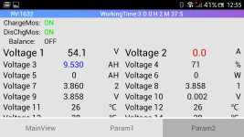
But after that, I found the capacity reading still going up. At about 40 minutes after unplugging the charger, I got the following readings.

Voltage of the pack: 54.1V
Capacity of the pack: 9.530AH (71%)
Highest voltage of the cells: 3.860V
Lowest voltage of the cells: 3.858V
Screenshot_2019-06-23-00-55-19.png

Why the capacity of the pack continue to increase after the charging had stopped? Is something wrong with the app?

PS: so far after the above screenshot, the capacity reading stays at 9.530Ah without going further up.
 
Depends on how that BMS is calculating %SoC.

All of the various methodologies are guesstimates at best.

Accuracy can only be (approximately) benchmarked against constant-current load testing.
 
john61ct said:
Depends on how that BMS is calculating %SoC.

All of the various methodologies are guesstimates at best.

Accuracy can only be (approximately) benchmarked against constant-current load testing.
Thanks for your reply.
I think the capacity increase after charging has stopped is not the real situation. If I am correct, then the methodology they are using is not good. Why don't they just do the calculation based on charge current, charge voltage and time (then once charge current = 0, the capacity will not increase)? This should not be difficult for them to do. Or the capacity should really rise a bit after stop charging?

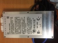
Or am I using an out dated app? My BMS is as shown below. Does anyone with the same brand has the same problem or not?
IMG_1375a.jpg
 
I've never heard of anyone relying on BMS only for accurate SoC data, even those costing many hundreds of dollars.

Much less doing benchmarking to determine the accuracy of their guesstimations.

That functionality is a minor sideline, not essential to their primary function of protecting the bank.

Most users just rely on accuracy at the top and bottom, from whatever regulates their stop-charge for the former, and their working LVC at the bottom.

Voltage levels and rough Ah counting are usually good enough for in between.
 
Has anyone used this with an Android tablet instead of a smart phone? Is it only for an app on a smart phone?
 
the app does not care if its a tablet. it might just look weird because of the screen size
 
Wondering if someone can point me to a good bms that would support 12lipo and 13-14 lion later on?
Almost all listings require you to choose cell count at purchase, but I would like it to be configurable by user (prefferably by app).
30A model should be enough.
 
So much great info in this thread!

I am looking to buy a 14s bms with bluetooth. Is this 60A unit from JBD still the best bang/buck recommendation https://www.aliexpress.com/item/32794186005.html

Perhaps more experienced users point would point me in a different direction?
 
I have two of those exact units working great for the last year. Buy one of the PC adapters as well, to access a few settings that aren't available in the bluetooth app, such as temperature limits.
 
I'd need one for 20S pack, around 100A, just to be safe, because I actually don't plan to go with more than 60A from battery. Bluetooth option required, or some nice color LCD display...

Do you guys have some best buy suggestion?
 
grga said:
I'd need one for 20S pack, around 100A, just to be safe, because I actually don't plan to go with more than 60A from battery. Bluetooth option required, or some nice color LCD display...

Do you guys have some best buy suggestion?

Sure, half of this thread talks about the "JBD" bms: https://www.aliexpress.com/item/32820588136.html
 
Which is considered "the best" for build quaily, longevity?

Higher price is OK.

How about higher current for faster balancing?
 
I would also like to know what the current recommendation is. I am building a homemade pack from different 18650s so I would like something with a high balancing current in case the pack is prone to going out of balance. Right now now I am considering just breaking a 14s pack in 2 7s sections for charging on a hobby charger and reconnecting them when its time to ride, but this would be a pain.

Any suggestions are appreciated.
 
Another thread, got this specific reco

Ant Smart BMS, aka RJXZS, Olive Leaf
300A and lower

https://www.aliexpress.com/item/32826820690.html
 
Frustrating mystery from this weekend. Bottom line, 5/14ths of my pack is dead, and I don't know what it could be other than some BMS malfunction, although I haven't pinned it down. BMS is this one, 14s 30 A.

I hadn't used my ebike in a couple months, although I connected via Bluetooth once per week or so. I figured that connection meant that things were probably OK, but I should have tapped over to the Battery State screen...

This weekend I wanted to fire it up, but when I connected and unlocked the FETs, I got the "IC front end error". It was reporting a pack voltage of 1.5 V. Shit.

I disconnected the battery and took it down to the workshop and cut off the shrinkwrap. The voltage at the terminals was indeed 1.5 V, but when I measured from the input side of the BMS instead of the output, I got 36 V. Whew, so not a total loss. 2.6 V/group means there's a current drain somewhere I have to track down, but the battery is still usable. Just have to charge it up and see if that resets the "IC front end error", whatever that means.

Connected the charger, no current. The FETs were still closed. Tried opening them with JBD Tools, no luck. Meanwhile, the BMS was still reporting nonsense voltages on all the groups.

Measuring the pins on the balance connector, it turned out that the pack wasn't at 2.6 V/group. Instead, the top 9 groups were at 4 V each (where I had left them when I charged last), and the lower 5 were at zero.

I did a quick visual to see if there were any shorts between the groups, but I couldn't see anything. And since I had closed the FETs while it was being stored, there shouldn't have been any external load, and if there were it should have drained the groups uniformly. The only thing connected to individual groups was the balance wires.

Not sure where to go from here in terms of diagnosis, but I have 10 GA cells with 3 cycles on them that are now useless. This is frustrating on its own terms, but I'm also concerned since I have a similar BMS on my scooter, which is a much larger pack. I have been regularly checking the cell voltages on this pack, and so far so good, but it makes me less confident about leaving the BMS attached to any pack of significant value.

Now, having vented my frustration, in 1k+ posts on this thread I think there's only been one other catastrophic failure (due to an endless balancing loop, IIRC), so I'm not recommending that anyone throw these in the bin. Just providing some anecdata and hoping it sparks some thoughts that could help me figure out what went wrong and help others to avoid a similar circumstance.
 
thundercamel said:
Probably the balance wire of group 10 broke. Did you measure the voltages directly at the cell groups, instead of at the balance wires?

Yep, I scratched through the Kapton and measured across 1-5 on the electrodes. Dead, dead, dead. Balance wires (and their solder connection to the electrodes) look intact. Thanks for the suggestion, though.
 
the FET on a balance port fried itself. it happens on crappy bms.
 
Back
Top