TSDZ2 mid drive with 860C, 850C or SW102 displays only -- Flexible OpenSource firmware (Casainho code only)

casainho said:
I gave you right now access to the wiki, so you should be able to upload the pictures and create the wiki page.

I created the page How to improve motor heat dissipation, please put there the contents: https://github.com/OpenSource-EBike-firmware/TSDZ2_wiki/wiki/How-to-improve-motor-heat-dissipation

Thank you. I am honored. I will do it with joy. I hope this upgrade will make cycling better for many people.
 
vadda said:
najbyk said:
The page about improving the heat dissipation from the motor is ready: https://github.com/najbyk/TSDZ2-cooling/wiki
Any suggestions are appreciated.
Before making an improvement, it is worth doing a continuous engine power test at a constant temperature. To be able to compare the results after improvement. After that write here how much more power you can get.

:bigthumb:
Thanks, very intresting wiki, well done
For the optional part, Sugru could be used instead of liquid silicon because it can be molded like Pongo

Of course it can. It will probably look better. This can be included in the wiki. I just had the silicone tube open and used it.
 
Hot weather coming here so will be taking some pointers soon thanks for sharing.

Btw I tried v0.20 b1 today. Commuting to work 17km each way. Firstly it was a very easy upgrade and setup from v0.16, I experienced no issues and the wiki was easy to follow.
I tried all modes but found emtb and torque modes far too tiring for commuting with a headwind. But I am looking forwards to trying emtb mode offroad soon where I think it will shine. Cadence mode was really scary giving very little control over speed, I don't know how the bbs guys do it every day although I can see if you had a long journey and were feeling lazy then it could come in handy. My favourite was power mode which combines torque and cadence, I was able to set it up so it chewed through similar power to my setup in v0.16 (About 220w at 30km/hr). It seemed identical at first but after doing a tight u-turn onto an uphill ramp I pushed a little harder so I wouldn't stall and my front wheel lifted in the air, wow what a buzz, finally some real power !!!
Other things I tried and loved were.. no resistance pushing back, walk mode and cruise mode. Cruise mode drops a couple of kms when it engages so not sure if im doing sometging wrong but it does work nicely once its engaged and will chew through your battery if you are not careful.
All in all it is the best release yet giving so many features and options for everyone's tastes.
Good work to all involved !!
 
najbyk said:
The page about improving the heat dissipation from the motor is ready: https://github.com/najbyk/TSDZ2-cooling/wiki
Any suggestions are appreciated..............
Thank you for this interesting approach for a better heat dissipation of the TDSZ2.
I have placed a link to it in another thread with different solutions for this TSDZ2 weakness, so all the solutions, that are mentioned on different topics, are found on one place too.
 
casainho said:
I gave you right now access to the wiki, so you should be able to upload the pictures and create the wiki page.

It is done. I have a problem with removing unneeded photos that I uploaded from the wiki server. Any idea how to do this?
 
Elinx said:
najbyk said:
The page about improving the heat dissipation from the motor is ready: https://github.com/najbyk/TSDZ2-cooling/wiki
Any suggestions are appreciated..............
Thank you for this interesting approach for a better heat dissipation of the TDSZ2.
I have placed a link to it in another thread with different solutions for this TSDZ2 weakness, so all the solutions, that are mentioned on different topics, are found on one place too.

It is a good idea to move the motor cooling discussion to the thread you suggested. Here is a thread about OSF and that was a bit off topic.
 
najbyk said:
Elinx said:
najbyk said:
The page about improving the heat dissipation from the motor is ready: https://github.com/najbyk/TSDZ2-cooling/wiki
Any suggestions are appreciated..............
Thank you for this interesting approach for a better heat dissipation of the TDSZ2.
I have placed a link to it in another thread with different solutions for this TSDZ2 weakness, so all the solutions, that are mentioned on different topics, are found on one place too.

It is a good idea to move the motor cooling discussion to the thread you suggested. Here is a thread about OSF and that was a bit off topic.
Done:


Maybe you can put a link on that page to the forum thread.

You should be able to deleted when seeing the picture on the browser like this:

 
casainho said:
......
Maybe you can put a link on that page to the forum thread.
You should be able to deleted when seeing the picture on the browser....

Thanks for the suggestions. It's ready.
 
Hello everyone,
yesterday I went for a trip with a positive climb of about 2000m, so for the first time I pushed my battery closer to the limit.
I've a 36v motor, OSF v.20 beta1, and a 620Wh battery (17.5Ah).
I set the motor limit to 450W for the offroad mode and 14A for current limit, so teoretically I could go from 570W (battery fully charged: 14A x 41V) to 420W (battery nearly empty: 14A x 30V).
With the battery fully charged and up to 1/3 remaining I noticed that my motor goes up the the 400-450W as expected from my limitations set, but as long as my battery goes down in voltage, the maximum power is reduced to approx 200W and does not reach to 400W anymore.
Theoretically it can still reach 400W (see above) but it does not.
The percentage left was around 20% (Voltage floating around 31V under load), as this is the first time I reach this level of battery I read carefully in the wiki and I found that the power is reduced in order to avoid to reach the cut off voltage.

It sounds to me reasonable, as it is perhaps better to have some assistance for longer time rather than the maximum until the end and then stop everything. What is the actual logic behind the "progressive power drop to increase the battery duration"?

Thanks
 
thineight said:
Hello everyone,
yesterday I went for a trip with a positive climb of about 2000m, so for the first time I pushed my battery closer to the limit.
I've a 36v motor, OSF v.20 beta1, and a 620Wh battery (17.5Ah).
I set the motor limit to 450W for the offroad mode and 14A for current limit, so teoretically I could go from 570W (battery fully charged: 14A x 41V) to 420W (battery nearly empty: 14A x 30V).
With the battery fully charged and up to 1/3 remaining I noticed that my motor goes up the the 400-450W as expected from my limitations set, but as long as my battery goes down in voltage, the maximum power is reduced to approx 200W and does not reach to 400W anymore.
Theoretically it can still reach 400W (see above) but it does not.
The percentage left was around 20% (Voltage floating around 31V under load), as this is the first time I reach this level of battery I read carefully in the wiki and I found that the power is reduced in order to avoid to reach the cut off voltage.

It sounds to me reasonable, as it is perhaps better to have some assistance for longer time rather than the maximum until the end and then stop everything. What is the actual logic behind the "progressive power drop to increase the battery duration"?

Thanks
There are some reasons what the current and/or power can be limited. If you are not happy, then you should go deep to learn and look at the variables shown on display and find the reasons why that happen to your motor, on your specific case. The firmware is OpenSource, it is full available available for anyone to see and learn how the system works. The true is that with original firmware and product, you could not go so far, you would need to be happy with what you get.

On 850C and SW102, we will be able to alert the user when some limit are reached (the graph on 850C already have 3 colors, base color, white and red, for warning and max values being hit). But user will need anyway to know how the system/motor works... maybe some wiki pages explaining how the battery low voltage limit works, how the max motor temperature works, etc.
 
casainho said:
thineight said:
Hello everyone,
yesterday I went for a trip with a positive climb of about 2000m, so for the first time I pushed my battery closer to the limit.
I've a 36v motor, OSF v.20 beta1, and a 620Wh battery (17.5Ah).
I set the motor limit to 450W for the offroad mode and 14A for current limit, so teoretically I could go from 570W (battery fully charged: 14A x 41V) to 420W (battery nearly empty: 14A x 30V).
With the battery fully charged and up to 1/3 remaining I noticed that my motor goes up the the 400-450W as expected from my limitations set, but as long as my battery goes down in voltage, the maximum power is reduced to approx 200W and does not reach to 400W anymore.
Theoretically it can still reach 400W (see above) but it does not.
The percentage left was around 20% (Voltage floating around 31V under load), as this is the first time I reach this level of battery I read carefully in the wiki and I found that the power is reduced in order to avoid to reach the cut off voltage.

It sounds to me reasonable, as it is perhaps better to have some assistance for longer time rather than the maximum until the end and then stop everything. What is the actual logic behind the "progressive power drop to increase the battery duration"?

Thanks
There are some reasons what the current and/or power can be limited. If you are not happy, then you should go deep to learn and look at the variables shown on display and find the reasons why that happen to your motor, on your specific case. The firmware is OpenSource, it is full available available for anyone to see and learn how the system works. The true is that with original firmware and product, you could not go so far, you would need to be happy with what you get.

On 850C and SW102, we will be able to alert the user when some limit are reached (the graph on 850C already have 3 colors, base color, white and red, for warning and max values being hit). But user will need anyway to know how the system/motor works... maybe some wiki pages explaining how the battery low voltage limit works, how the max motor temperature works, etc.

Perhaps I wasn't clear in my post.
I am very happy with the current OSF firmware v.0.20beta and with the settings.
I noted a drop in peak power when the battery starts to be around 25% (this is the first time I discharged the battery that much during a trip) and I read in the wiki this limit is somehow foreseen to further extend the battery duration.
I just wanted to understand the logic in simple words. As I am not a professional programmer, it will take a week for me to open up the code, understand it and find the place where this logic is shown.

To me is sufficient a top-level answer like "for a 36V battery (range 41-->30v) from 34v the peak is linearly reduced to, say, 100W because .... "
 
thineight said:
Perhaps I wasn't clear in my post.
I am very happy with the current OSF firmware v.0.20beta and with the settings.
I noted a drop in peak power when the battery starts to be around 25% (this is the first time I discharged the battery that much during a trip) and I read in the wiki this limit is somehow foreseen to further extend the battery duration.
I just wanted to understand the logic in simple words. As I am not a professional programmer, it will take a week for me to open up the code, understand it and find the place where this logic is shown.

To me is sufficient a top-level answer like "for a 36V battery (range 41-->30v) from 34v the peak is linearly reduced to, say, 100W because .... "
When you learn for you, please write a wiki page to help the next ones.
 
thineight said:
Hello everyone,
yesterday I went for a trip with a positive climb of about 2000m, so for the first time I pushed my battery closer to the limit.
I've a 36v motor, OSF v.20 beta1, and a 620Wh battery (17.5Ah).
I set the motor limit to 450W for the offroad mode and 14A for current limit, so teoretically I could go from 570W (battery fully charged: 14A x 41V) to 420W (battery nearly empty: 14A x 30V).
With the battery fully charged and up to 1/3 remaining I noticed that my motor goes up the the 400-450W as expected from my limitations set, but as long as my battery goes down in voltage, the maximum power is reduced to approx 200W and does not reach to 400W anymore.
Theoretically it can still reach 400W (see above) but it does not.
The percentage left was around 20% (Voltage floating around 31V under load), as this is the first time I reach this level of battery I read carefully in the wiki and I found that the power is reduced in order to avoid to reach the cut off voltage.

It sounds to me reasonable, as it is perhaps better to have some assistance for longer time rather than the maximum until the end and then stop everything. What is the actual logic behind the "progressive power drop to increase the battery duration"?

Thanks

thineight said:
I am very happy with the current OSF firmware v.0.20beta and with the settings.
I noted a drop in peak power when the battery starts to be around 25% (this is the first time I discharged the battery that much during a trip) and I read in the wiki this limit is somehow foreseen to further extend the battery duration.
I just wanted to understand the logic in simple words. As I am not a professional programmer, it will take a week for me to open up the code, understand it and find the place where this logic is shown.

To me is sufficient a top-level answer like "for a 36V battery (range 41-->30v) from 34v the peak is linearly reduced to, say, 100W because .... "

First of all, I am very happy that you are satisfied with the 0.20.0 Beta 1! I know I have stated this a lot of times but the firmware will only get better in the future. It is a very solid foundation!

Second of all, let us try to answer your questions regarding the motor power limitations at low battery voltages in respect to the defined minimums. I will try to be very clear and try to convey the basic logic. Note that the explanation will be very simplified but if anyone wants a more in-depth explanation I will happily provide that.

--------------------------------

There is a current controller in the firmware that controls and limits the amount of current that goes to the motor. This is how we control the power. But it is more accurate to say that this is how we control the motor torque. The current is proportional to the torque.

The current controller will have several parameters that limit the amount of current at any given time. One example is the active riding mode limit. If we require 200 W of power and the battery voltage is 50 V we need 4 A of current. So the current controller in the firmware will send instructions to the motor controller to limit the current to 4 A.

Another parameter is the maximum battery current. If we set that to 3 A the current controller will prioritize this lower limit compared to the previous example of 4 A. The current controller always uses the lowest limit.

Yet another parameter is the low voltage cutoff. If the voltage gets below the low voltage cutoff the current controller will automatically lower the current until the battery voltage is at or above the low voltage cutoff.

So how do we control the current? Basically, we control the timing of the transistors in the motor controller. This is another way to say that we control the duty cycle. By changing the duty cycle we change the average voltage applied over the motor phases and therefore the average current that goes through the motor phases.

By increasing or lowering the duty cycle we can change the amount of current that flows through the motor. So when we get to the battery low voltage cutoff we immediately decrease the duty cycle. This will in turn decrease the current flowing through the motor and as a result the motor power will go down.

Here is the current controller in our 0.20.0 firmware:

Code:
  // check if to decrease, increase or maintain duty cycle
  if ((ui8_g_duty_cycle > ui8_controller_duty_cycle_target) ||
      (ui8_controller_adc_battery_current > ui8_controller_adc_battery_current_target) ||
      (ui8_adc_motor_phase_current > ADC_10_BIT_MOTOR_PHASE_CURRENT_MAX) ||
      (ui16_motor_speed_erps > ui16_max_motor_speed_erps) ||
      (UI8_ADC_BATTERY_VOLTAGE < ui8_adc_battery_voltage_cut_off) ||
      (ui8_brake_state))
  {
    // reset duty cycle ramp up counter (filter)
    ui16_counter_duty_cycle_ramp_up = 0;
    
    // ramp down duty cycle
    if (++ui16_counter_duty_cycle_ramp_down > ui16_controller_duty_cycle_ramp_down_inverse_step)
    {
      ui16_counter_duty_cycle_ramp_down = 0;
      
      // decrement duty cycle
      if (ui8_g_duty_cycle > 0) { --ui8_g_duty_cycle; }
    }
  }
  else if (ui8_g_duty_cycle < ui8_controller_duty_cycle_target)
  {
    // reset duty cycle ramp down counter (filter)
    ui16_counter_duty_cycle_ramp_down = 0;
    
    // ramp up duty cycle
    if (++ui16_counter_duty_cycle_ramp_up > ui16_controller_duty_cycle_ramp_up_inverse_step)
    {
      ui16_counter_duty_cycle_ramp_up = 0;
      
      // increment duty cycle
      if (ui8_g_duty_cycle < PWM_DUTY_CYCLE_MAX) { ++ui8_g_duty_cycle; }
    }
  }
  else
  {
    // duty cycle is where it needs to be so reset ramp counters (filter)
    ui16_counter_duty_cycle_ramp_up = 0;
    ui16_counter_duty_cycle_ramp_down = 0;
  }

Notice that we check several parameters and if either one of those returns true we will decrease the duty cycle -> current -> power.

So at any give moment, the system will give us the maximum amount of power (actually current/torque) provided it does not go over the defined limits.

--------------------------------

EDIT: If anyone found this interesting and would want it on a wiki page, please let me know!
 
Nice so it LVC is reached then power keeps dropping to ensure LVC is not violated again ?

I assume that eventually the power cannot be dropped any more and the motor will turn off ?
 
jbalat said:
Nice so it LVC is reached then power keeps dropping to ensure LVC is not violated again ?

I assume that eventually the power cannot be dropped any more and the motor will turn off ?

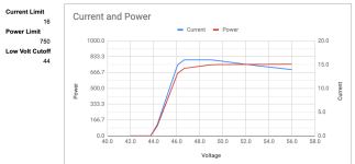
I'm not one of the developers, though I do work on a lot of large battery systems. Attached is a quick graph I put together showing the interaction between the three main limiters of power - your current limit, your power limit and your low voltage cutoff limit.

Screen Shot 2019-10-07 at 5.21.14 PM.png

In this case, current is limited to 16A, and power is limited to 750W, on a nominal 52V battery. The graph shows the maximum power available, and the resulting current, at the full range of the battery's nominal voltages (full to empty). Because a battery under load has a lower voltage than it's nominal state (based on the internal resistance), at voltages approaching the cutoff, the current must be reduced to "creep up" on the limit, rather than overshoot it.

The logic is:
  • Calculate a desired power from the torque and cadence, depending on the assist level selected
  • If that power is greater than the power limit, reduce it to the power limit
  • Calculate the current from the selected power from step 2, and the current voltage
  • If that current is greater than the current limit, reduce it to the current limit
  • Increase the current to the selected value, and measure the on-load voltage
  • If the on-load voltage drops below the LVC, reduce current until it reaches the LVC exactly

Hope that helps!
 
jbalat said:
Nice so it LVC is reached then power keeps dropping to ensure LVC is not violated again ?

I assume that eventually the power cannot be dropped any more and the motor will turn off ?
You guys should try and see. Just adjust LVC on display to a value near your battery current voltage. Also note that battery reacts differently when it is near discharged, so you can also try when it is really full discharged.
 
Is it electrical possible to conect a DS18B20 Temperatursensor to the Brake Input so we can use the trottle to the same Time with only some Firmware changes?
 
On the topic of LVC, can anyone tell me what an ideal LVC setting is for the EM3EV 52v (17Ah). I currently have it set to 42 (14 series * 3), but not sure if I can go higher since the Samsung cells are rated at 3.6V. Range is most important to me.
 
CatfishMan said:
On the topic of LVC, can anyone tell me what an ideal LVC setting is for the EM3EV 52v (17Ah). I currently have it set to 42 (14 series * 3), but not sure if I can go higher since the Samsung cells are rated at 3.6V. Range is most important to me.

At 3 volts per cell you are at about 10% state of charge. Assuming you've set the resistance values in the controller (your battery internal resistance plus your cable resistance), then I wouldn't go any lower than 42V. I have a similar pack with the Samsung 30Q cells, and am using 44V right now, though I'm going to experiment with 43V. Like most battery settings, the more aggressive you set the value, the more range you'll get, but you'll trade lifespan.
 
Hello,
I'm new to the forum, but have been following the discussion for a while.

I'm ready to purchase a TSDZ2 kit for a build for a family member. I'm planning to get the 48v 750w versions and install the Open Source Firmware. I'm pretty technically proficient and don't mind tinkering, but for the bike I'm building for my mother, I need it to just work, once I have set it up and tuned it.

If it's ok, I have a few questions first.

1) As regards the TSDZ2 motor itself are there more recent revisions, and if so, what should I look for to get the most recent version?

My other questions have mostly to do with which display to order to install the firmware on. As stated earlier I need this to be as stable and user friendly as possible for a non technical family member.

2) What is the current best device for installing the firmware? (I am on a bit of a budget, so would like to avoid the 850c as it is more expensive both for the device and for the bootloader box, which together add well over $100 to the build. However if that is the best option, so be it.)

3) I was going to go with the KT LCD3 as it could be flashed with the same STLink v2 device as the motor and seems to have the most mature firmware, however in reading through the discussion, it seems that the developers are no longer in favor of this device. Is this still a viable option?

4) Will the LCD3 continue to be developed, and what are it's limitations?

5) My other thought was the SW102, as it is smaller and cheaper than the 850c and uses the same STv2 programming cable. Is the Firmware for this device at a stable point?

That's pretty much it. My only other questions may well be better answered in another form, but I'll try here first.

1) I'm installing on aroad bike, a specialized carbon frame. Are there any particular problems with installing this more onto a road racing style frame?

2) What are the options for keeping the current double chaining gearing? (Currently 110 bcd cranks.)

3) Lastly, considering we do some touring in Colorado, how well does the motor handle sustained climbing for say an hour or more? What settings would be best for this scenario?

Thanks,
Kyle
 
KWTri said:
My other questions have mostly to do with which display to order

If you want it simple and cheap, just use the display, that comes in bundle with the motor, no need to flash the display at all.
https://endless-sphere.com/forums/viewtopic.php?f=30&t=98281

Tutorial:
https://github.com/stancecoke/TSDZ2-Smart-EBike-compatible-with-original-VlCD6-display/wiki

regards
stancecoke
 
Thanks to casainho my issues with the white screen and the inverted screen on the 850C were solved with version 4.2. and I could finally ride my bike. Wonderful experience already with OSF version 19.0 - thanks to everybody contributing!

Last weekend I added the temperature sensor and improved the heat dissipation (combinations of 1, 2 and 5 mm thermal pads to touch the housing everywhere on sides and top). I then went for a steep 200m test climb under high load (always over 20 km/h and 500-700w). The motor temperature did not go over 67°C at air temperature of 15°C (even with the low temperature limit set at 70°C - so no thermal management from the firmware involved). Yeah!

I have two questions and a suggestion:
- I can't limit the power no matter which settings I use (offroad mode on/off). Any ideas what I must do to make it work?
- Is it possible to go for OSF 20.0 together with my 850C version 4.2?
- The L and B signs for lights and brakes on the 850C are very hard to see when riding (for me) - I would have to put on my glasses which is too dangerous. For the brakes it is no problem as I can see something lighting up when I pull the lever and I don't care if it is a B or an X or anything else. But for the lights/L it would be great to have it a little bit bigger/fatter in the next firmware version so I can see if the light is on also during daytime rides.
 
Thanks Buba and phidauex, now it's a bit more clear the reason behind the power reduction.

Generally speaking, what is a reasonable LCV value for a 36v battery? I've to double cheek what I set initially, I remember 29 or 30v (2.9-3.0v per cell). Reasonable?

Thanks
 
Shameless thank you plug! I have been following this TSDZ2 thread since February slowing gathering supplies and finding time to install. I have now put 1.4k miles on my build and its a joy. I use for my commute into work 20 mile round trip.

I installed the v0.20-beta.1 last night and am loving it! The options for the flashing lights is amazing! Have not got a chance yet to play with the other drive modes but excited to try.

Things I am excited to look into:
- The thermal mod with temp sensor
- Brake sensor
- Does anyone bother with gear shift sensor?
 
has the startup boost funcionality been removed from 0.20? I don't see it in the 0.20 configuration manual on the wiki
 
Back
Top