APL's DIY axial-flux motor

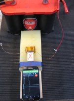
I did this experiment quite a ways back, you can see the slope at the top of the scale, heat goes up and magnetism
goes down. Unless I'm missing something, makes sense to me. But it's a well known fact that the colder a conductor
is, the less resistance electricity has to flow. The opposite should be just as true.

Magnometer.jpg

I suppose I should pile some dry ice on the coil and see if the slope goes back up.
 
This is at short circuit condition which is not like in a motor since controller regulates voltage and current.

An example of this is my previous motor, driven at 72v and 0.015 ohm phase-phase resistance would give 4800A at short circuit. That would be interesting. Doesn’t matter for the magnetic field creation if it doubles resistance, unregulated current would then be 2400A.
Point is that there’s normally enough voltage to drive the needed current to create the field.

Off course efficiency is way worse at higher temperature and especially the magnets’ field strength take a dive.

I’d still recommend looking at efficiency (root cause to heat) rather than cooling strategies.
 
Efficiency is a compromise. It's impossible to design a motor with high efficiency over its entire operating range, instead operating conditions must be adjusted to make the most of the motors characteristics and that's done with the control system.

A well designed hub motor can be over 90% efficient but only within a limited range. Stall torque is the least efficient so if it's unacceptable to run at less than 90% efficiency then you'd have to pedal to, say, 8mph before powering the motor. More realistically you'd run the motor at, say, 20% output from standstill ramping up to 100% as efficiency rises and tapering off again towards peak rpm.

That's easy enough to do just with thermal limiting, monitor temperature and throttle back over a certain point and that should really be a essential feature of any motor controller capable of pushing a motor beyond its thermal limitations. Any electric drive system that can't reach those limitations is losing out somewhere, either in flexibility by only ever running at its ideal efficiency range or in performance by being over-specified to stay within thermal limits outside its ideal efficiency range.

The control system is the key to maximising performance, internal combustion engine outputs and efficiencies couldn't have risen so much in recent years without powerful engine management systems to keep them operating within strict limits and prevent them destroying themselves. Exactly the same thing applies to EVs, BLDCs are capable of incredibly high outputs but power is nothing without control.
 
A properly cooled motor is an efficient motor as APL said. Why are you spliting the two ? A motor efficiency or figure off merit can be described by the torque constant divided by the root of the impedance.
A cooler motor mean a lower resistance and more power for less coper, less weigth and by so a better power-density.
The copper impedance increase is 0.393% per °c. So at 20 ambient and let's say a safe 80°c it's a 23.5% increase in resistance. That's a Big hit in efficiency that can be shifted by proper cooling.

I agree with Stan, driver control is really a Big thing if we want to take the most out of a motor. If we want the best everythings need yo ne consider.

Envoyé de mon Redmi Note 3 en utilisant Tapatalk


Control and cooling is not the same. Read the ”Definite cooling...” thread by justin (ignore the babble later on in the thread)
https://endless-sphere.com/forums/viewtopic.php?f=2&t=48753&sid=04189781767f5051d90f7c9a6a2f4d50#p718603
it’s one of the best here. a lot of good data and facts.

If you have an open motor you have already the majority of the cooling achieved. If you need massive cooling more than this then you’re overpowering your motor.. Solution is not cooling the inefficient motor but to regain higher efficiency with higher gearing/lower load or a bigger motor.

Many here are coming from the assumption that an overpowered motor is solved by cooling. If you’re not one of them then i agree with you. Cooling is good. It’s only that it’s not a solution to all problems.

Prio 1 efficiency
Prio 3 cooling

Don’t know what prio 2 is.. having fun? Buying your girlfriend a nice drink?
 
Large mid-drive motors don't usually need a lot of cooling, unless your a power hungry fool. (I'm afraid I might be
becoming one soon) Small RC motors seem to need extra cooling. (usually bottled up in a case with lots of gears)

Hub motors are most always overpowered, and could use more cooling, especially since they are usually sealed. The
Marand style air core motors like the ones that are being made here tend to have more cooling issues, but only at low
speeds and in a hub motor fashions. In their intended higher rpm range not so much.
I'm simply saying more, or better cooling can't hurt.

There are lots of water cooled axial's available, not so much being overpowered, but extreme duty. Although the two
are virtually the same.

I haven't read Justin's thread yet, busy morning, but I'll do so soon.
 
more power = more amps more turns = more ohmic losses = less efficient at low rpm
 
No.
more power = more amps or more volts :wink:
more turns = same ohmic losses given same fill factor (roughly, there are some added losses on low turn motors)


You should read this:
https://endless-sphere.com/forums/viewtopic.php?f=30&t=102934#p1505648
 
@APL my two cents: don't spend too much time on the cooling fans theory.
I'm not sure yet which design you are settling on for your motor, but if it is anything similar to your previous one, then I suggest you to consider the following option: 3D print some covers.
This way, you could very easily experiment with as many designs as you want for the blades, and even protect a bit the motor from debris and other stuff depending how you build the thing.

I made a very quick design for you to see, it's ugly so don't focus on the esthetics, but there is no doubt it can look very nice if you spend a bit more time than I dit on the blades shape.
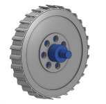
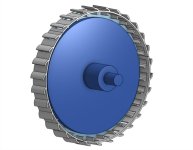
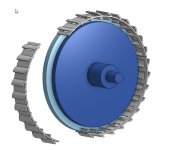
Basically the idea is to print 3 covers to install on the motor perimeter:

APL motor  Part Studio 1 - Google Chrasome.jpg
APL motor  Assembly 1s - Google Chrome.jpg

This way, it's easy to install with just a few screws and extremely easy and quick to print.
edfas.jpg

You could tweak the blades shape all you want, from both the inside and outside to get the best possible air flow.
dffds.jpg

I think it is a cheap and easy solution, plus it is very lightweight, which is good for keeping rotation masses down. It could be made out of some relatively heat resistant plastic like nylon, PC or ABS, if heat turns out to be an issue (I doubt it will, except maybe if you plan on using PLA, but it's not well suited for outside conditions anyway so don't).
 
larsb said:
No.
more power = more amps or more volts :wink:
more turns = same ohmic losses given same fill factor (roughly, there are some added losses on low turn motors)


You should read this:
https://endless-sphere.com/forums/viewtopic.php?f=30&t=102934#p1505648

more turns = more length = more ohmic losses
 
Yes, you’re correct when only looking at the value of the losses but it’s not what matters in motors.

More turns = more field/ amp = same ohmic losses per torque. Haven’t you heard the word ampereturns?

Read the post..
 
Thanks Dui, ni shuo de dui, wow, if thats a quick rendering then you'r fast! I like the way you think,.. I was saying
something like that a few post back. I was thinking six pieces that fit in between the six spacers.
Perfect for 3D printing, and can be changed out and experimented with.

I have a buddy with a printer that can print it for me, plus I've been keeping an eye out for Craigslist deals to get an
idea on what a used unit will go for. I've seen Gen. 5 Makerbot's for five bills, and others for less.
But I'm just getting started on learning about these things, and don't plan on pulling the trigger any time soon.

All the more reason to get this Cad program going. I'm getting excited at the prospect of being able to do all this stuff!
Hopefully I can teach this old dog some new tricks. :)

I get to pick up the new PC in a few days, and I'll finally get to start messing with the program at long last. I can't even
tell you what the specs are, other than it has a new OS, i5, and it's got plenty of ram and memory. So who cares,..
just give me that key board! :thumb:
 
If you're getting a printer the lowest price units on ebay are very hard to beat imho, usually around $100. It's easy enough to splash out on something higher priced later when you've a better idea what you need (multihead, bigger bed etc.). Some print jobs can take an entire day so a second unit wont go unused plus many parts are likely to be common (stepper motors, filament feed, printhead, belts etc.), always good to have spares.

There's not really a whole lot higher priced units offer over the cheaper ones, rigidity isn't great but that's very easy to fix. Enclosures are a big plus with higher priced units imo, not essential but consistent temperatures are a key to consistent quality, easy enough to make one but most of the higher quality printers will already have one.

Print height can be a pain with cheap units, always needing tweaking. A better z axis limit switch is a big improvement but there are also print head mounted height sensors that entirely eliminate the issue. Most reasonable quality printers also use limit switches and have the same issue (to a lesser degree), the same print head mounted sensor would work on either.

It's worth getting spare nozzles too, brass ones will keep working ok for a long time (hundreds of hours) but print quality drops off pretty fast (tens of hours). Stainless isn't really any better, there are some crazy expensive ones such as ruby but they simply don't add up, the brass ones are so cheap that you could change them every day and still be spending less
 
Thanks stan.distortion, thats just the kind of info I need as I've just started to crack the door open into this world.
But It seems like I keep running into a need for one every time I turn around. I could have REALLY used one on this
last motor. Making a spacer for bonding the magnets would have been a snap, just to mention one.
It's going to be one of those tools where you just don't know how you ever got along without one.

I know it's been mentioned before, but in the back of my mind I keep thinking that it might be possible to make a
(mostly) 3D printed axial motor thats usable. Perhaps a future project. :)
 
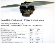
I don't think we've covered the LaunchPoint motors, unless I missed it. So I'll include it,.. just because.

Most of you have probably seen them for quite some time, but I just ran across it. Typical air core Halbach style.
But this one is interesting in the fact that it's in a in-runner fashion. Talk about cooling!

LaunchPoint; https://cdn2.hubspot.net/hubfs/53140/DHA-050-1p5-75-1-2T3PY%20Frameless%20LP%20motor%20data%20sheet%20v1_js.pdf

1.5 kw for a 5" motor is impressive, but for a bike it would have to really be geared down from 7500 rpm.
Mostly I think the cage housing and in-runner aspects are interesting.

IMG_2070 copy.jpg
 
Earlier in this thread there are a few pics of "strange looking" coils:

file.php


file.php


With strange i mean that these coils have the entire widing wire including endturns within the magnetic circuit, but since i always had the meaning that endturns do not contribute to torque, i did a bit of research and i want to share my findings here.

First of all yes it is true, on motors with permanent magnets the torque is generated by the Lorentz force and therefore indeed only one part of the winding, namely the part which is parallel to the magnets, contributes to torque.
On axial flux motors it is the part of the winding which run in radial direction, and on radial flux it is only the part which runs in axial direction which does something useful.

So why making coils like this if they are so inefficient?
I think the answer is that these coils are normally used on motors without permanent magnets where torque comes from reluctance (Swichted Reluctance Motors) and so the entire winding, no matter in which direction it goes, contributes to torque.

What i also found really interesing is the explaination of how round coils (like often used on coreless motors) work, and that they are less efficient as if the wires would be straight.

here is the source:
https://things-in-motion.blogspot.com/2019/07/bldc-pmsm-end-turns-and-torque.html
The author was doing a really good job in packing so much information in such a short and easy to read article. Kudos to him.


From what I see there's a dual rotor single armature axial both rotors spin opposite and the armature sits in the centre fairly isolated heat path.
Then there's the picture above from what I can find it's extremely power dense the armatures are wound to have the same effect in the rotor from both sides and the heat path is direct to the case for air or water cooling from the demonstration video I found they used litz windings bug as possible to fill the slot with one turn no specs really given of kv weight and watts etc.

The thread is long I'm going to need a few days catch up what you have done I only now have come across it love to see a blueprint put forward for hobbiest.
 
madin88 said:
...
I think the answer is that these coils are normally used on motors without permanent magnets where torque comes from reluctance (Swichted Reluctance Motors) and so the entire winding, no matter in which direction it goes, contributes to torque.
...
here is the source:
https://things-in-motion.blogspot.com/2019/07/bldc-pmsm-end-turns-and-torque.html
...

Hi madin88,

From your link:

Another motor design is one which abandons the Lorentz force completely and instead relies on a difference in magnetic reluctance to generate a force.

I do not believe one gets to choose when and where the Lorentz force law applies. He may choose to use a different method to analyze or calculate force or torque, but universal principles still apply. So in a nutshell, I don't believe end-turns contribute to torque production in any motor, or generator, including reluctance machines. But is kinda off-topic, so let's just leave it or use a different thread.

Regards,

major
 
I've designed a 3700 Nm , 36cm diameter and 30 kg weight motor in my computer but who knows if a real prototype would work, I always read that FEM simulations reach 95% accuracy but it's all circumstantial. Albeit IMO a diy motor is for fun and you shouldn't bother with high efficiency or power density.

End turns have one end going in and one end going out so in summation the force cancels out and the length is so small and outside the magnetic flux concentration that is almost zero contribution to overall torque, it's useless to talk about end turns.
 
ecotech said:
I've designed a 3700 Nm , 36cm diameter and 30 kg weight motor in my computer but who knows if a real prototype would work, I always read that FEM simulations reach 95% accuracy but it's all circumstantial. Albeit IMO a diy motor is for fun and you shouldn't bother with high efficiency or power density.

End turns have one end going in and one end going out so in summation the force cancels out and the length is so small and outside the magnetic flux concentration that is almost zero contribution to overall torque, it's useless to talk about end turns.
Length can be a big problem, the coreless design I'm playing around with has about 2/3rds of the winding length as end turns and only about 1/3rd running radially. That's due to overlapping windings but a lot of industrial induction motors are the same, more copper at either end of the stator than there is running through it.

For coreless I'm fairly sure those end turns are a dead loss, that they contribute nothing to torque but I'm not so sure if it's the same with cores. Everything I've read on end turns says they contribute nothing but take a look at the individual core segments/wedges that APL has been posting, would the field be as strong if they only had windings running up the sides?

Another way of looking at it, if you had 2 pieces of square steel bar and wound one tight all the way around and the other with a big loop that was only close to 2 sides, would the field strength on the ends of the bars be the same? I don't see how it could be, the one wound tight would surely have a stronger field than the one wound with only 2 sides touching (and a big gap between core and windings on the other 2 sides).

Laminations would no doubt have an effect but in APLs case there are no laminations and with the individual cores there's no reason to consider any other options, the end turns are ideally placed but conventional thought seems to be "end turns are useless" and it might not be that simple.

APL said:
Thanks stan.distortion, thats just the kind of info I need as I've just started to crack the door open into this world.
But It seems like I keep running into a need for one every time I turn around. I could have REALLY used one on this
last motor. Making a spacer for bonding the magnets would have been a snap, just to mention one.
It's going to be one of those tools where you just don't know how you ever got along without one.

I know it's been mentioned before, but in the back of my mind I keep thinking that it might be possible to make a
(mostly) 3D printed axial motor thats usable. Perhaps a future project. :)

Lol, if you're anything like me then you'll have about a year of "damn, I should have used the printer for that job" first ;) It's good you have someone there who's already familiar with them as there are load of little points that can take hours of digging through the internet to find answers to. Like the nozzle lifespan for example, there aren't any hard and fast figures for wear rates and the best advice seems to be have plenty of new ones to hand and if in doubt, change it.

Something maybe worth considering from the start is materials. I started with PLA and it seemed like the best route but in hindsight I should have gone with ABS. I'ts harder to work with and smells but neither point is as bad as they seem when reading up and anything done in ABS is permanent, everything I've printed in PLA has a throwaway feel to it (it biodegrades).

But the big point is support materials. You can't print overhangs, anything over about 50-60 degrees needs to be supported and it can be a real pain to remove afterwards (often impossible). That's where a multihead printer can be a total game changer, water soluble filament can be used for supports but only with at least 2 print heads, one for the construction material and one for the support material.

It doesn't sound like a big deal but the learning curve between designing for regular engineering/fabrication and designing for 3d printing is surprisingly steep (for example simple things like threaded holes take a lot of tweaking). If you could treat support as an inconvenience rather than a show-stopper from the start then it could make that learning curve a lot easier, you get used to avoiding overhangs after a while but in many cases there's simply no other option.

I'm not sure it's worth the extra initial cost and complication of starting out with a multihead printer but if you're on the fence about what printer to get it's certainly worth considering imo. It's one point where the ultra-cheap printers lose out, they can be converted to multihead but really need things like height and rigidity sorted out first.

On that note, have to give a shout out to Ultimaker printers. I don't have one and they're a little steep on prices imo but if they're anything like as good as their slicer software (Cura) then they're worth the extra cost. That software has been a godsend, open source, endless config options and it just works, maybe some commercial offering are on par but I don't think there's much room for improvement.
 
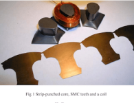
Madin88, I like both of those links. The first picture, with the organic looking SMC cores takes core design to the next
level. Something that can't be done with laminations, and I imagine with a lot of simulations and coil winding technique
could be taken even further,.. more organic,.. almost like it grew that way.
Axial composite and laminate hybird.png

Theres an awful lot of windings on there, so I figure it must be a pretty high voltage motor.

I have to wonder if the radial and end turn wires on a coil that is completely under a tooth even mater.
If theres enough steel in the overhang on top of the coil, then the tooth face should act no different than a permanent
magnet face.

The core going through the coil transfers the flux from the middle of the coil out to the end, and the tooth face area
widens the flux, which also diminishes it a bit.
At least,.. thats how I understand it.

I've always been told that only the radial wires lend to torque as well, but we have to put this information into context.
Certainly true on radial motors, which tend to have long armatures, and on air core motors for sure, but there are other
configurations that are a little different?

The coil in Fig 1 is a trapezoid, but approaching round. I think this is to shorten the wire, and thus the resistance, as
Lebowski has been saying should be done.
You could go all the way to a round coil, but now the corners of the tooth are farthest away from the center flux, so it's
best to remain slightly trapezoid.

Most axial motors don't take efficiency and design quite this far, and have the usual square-ish trapezoid, with little
lip overhang, and some don't use any at all. Probably do to gains and cost.

I also like the "Things in motion" blog you referred to in your post. He explains things in a really understandable way.
I should make it a point to read some of that blog every day, it's lots of pages, and covers most everything about motor
building stuff without giving you an instant headache. :thumb:
 
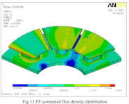
Heres also a flux density image of those cores, and the original link, in case anybody interested.

Computed flux density.png

Composite Axial motor. https://www.semanticscholar.org/paper/Axial-Flux-Motors-Using-Compacted-Insulated-Iron-Jack-Mecrow/5ef72ec69d71b583f9f22a1e85f6f0aa8a59553c
 
It's a bit confusing, and I'm not too sure about any of it, but one thing to keep in mind is the fact that most motors
in the past have been made with laminations. When laminations are used the end wires have to protrude past the
core on the ends because you can't make a lip there, as the laminations are not supported and will brake off.

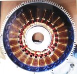
Much like this laminated motor, where they don't even try to tighten up the end windings.

IMG_2071 copy.jpg
From article; https://www.semanticscholar.org/paper/Fractional-slot-concentrated-winding-axial-flux-Capponi-Donato/a864d9b1873d50cfb86cb3d073ecf0507fa91a05

Because the end windings are generally loose and not tight to the core, plus being away from the flux path on laminated
motors, they do not contribute to the core magnetization. Because of this, in general, the information has always been
that end windings do not contribute.

If you wrap a iron bar tightly with a coil, all of the wires are contributing to the core flux, no matter which direction
they are going, like stan.distortion was saying earlier.
Especially if you cap all the windings off with a steel tooth lip, as is possible with a SMC core design.

(Sounds good, but am I right, or am I way out of line?) :lol:
 
Hi APL,

I'll refer you to a thread on end-turns mentioned before. This post in particular. There could be iron inside the solenoid coil. Makes no difference on the magnetic path outside the coil.

major said:
major said:
...
BTW, I used the term "core" when addressing Ampere's Law because of the motor context. It is actually the magnetic path. So in your solenoid examples the magnetic path completely surrounds the coil, therefore there are no end turns. In the motor FEMM you see only a cross section. Only leakage flux will encompass end turns which, in a decent design, will be very little.

downloadfile.jpeg
file.php


Notice the magnetic path (thru air) completely surrounds the coil, so there are no end turns. However when you have a ferromagnetic path (core, back iron, and such completing the magnet circuit) then there are portions of the coil turns outside the path which are noncontributing end turns. This is described in Ampere's Law as I explained in my first post, second reply in this thread.

major
 
Back
Top