Mongoose DX project

I think U-bolts are looking better and better as we progress here.

The hose clamps may, indeed, work. U-bolts are more elegent, and machined clamps are more elegent than the U-bolts. But, whatever works is fine.

I think a simple mounting plate for the foot that is drilled for U-bolts would make this alot easier for most people.

Matt
 
Hi,

recumpence said:
The hose clamps may, indeed, work. U-bolts are more elegent, and machined clamps are more elegent than the U-bolts. But, whatever works is fine.

More elegant and a lot stronger. IMO using hose clamps to make weak U-bolts isn't a great idea. It would be almost as easy to use real U-bolts. I don't see the advantage.

recumpence said:
I think U-bolts are looking better and better as we progress here.

I think a simple mounting plate for the foot that is drilled for U-bolts would make this a lot easier for most people.

Matt

I agree that a design built to accommodate U-bolts is a good idea. Would it be less expensive to provide feet (maybe an optional design) that is designed to accommodate the U-bolts directly?

Miles said:
U-bolts in conjunction with a split ring? With an external groove on the split ring, perhaps?

The grooved split ring idea looks good but are they worth the cost? They would definitely (I think) require a different size for each different frame tube size.
 
MitchJi said:
The grooved split ring idea looks good but are they worth the cost? They would definitely (I think) require a different size for each different frame tube size.

I would have thought they'd be quite cheap to produce. Maybe 2 or 3 different ring bores for each U-bolt size? Anyway, it needs something to give an accurate fit to the tube and spread the force a bit....
 
Miles, why don't you make the top side of the U-bolt spacer flat? That will give the foot something to rest against.

It's another good idea, but in my opinion it would be best to develop a solution that does not require custom machining anything else.

Anyway, for those of you who don't believe in my hose clamp solution, I tested full throttle with the rear brake applied for >10 seconds pulling about 60 amps. The magnets in my motor came unglued before the hose clamps budged. :shock: Took care of that one quick with some CA glue. But yeah, hose clamps are pretty awesome. As soon as I get my project boxes in and electronics mounted I'll take it for a real test ride.
 
Ja, a groove in the foot and my personal favorite: angle metal.

ubolt1.jpg
This model features American threads. (heh-heh)
 
recumpence said:
I will start drawing them up this weekend.

I also may make a drive mount that bolts to the rear disc brake mount so a drive coule be mounted there driving a sprocket on the disc brake flange. That would get more people going as well, though not as cool as a frame mounted drive.

Matt
Do it do it do it! It is a very slick idea that was designed into my drive units.
 
TylerDurden said:
Ja, a groove in the foot and my personal favorite: angle metal.

I don't think I've ever seen angled U- ..er V-bolts like that...? :shock:

While you all have fine and wonderful ideas, I'm trying to go for off-the-shelf and cheap. No custom machining.
I.e. completely and totally opposite from buying Matt's drive. :mrgreen:
sstboltclamp.jpg

T-bolt hose clamps are used in very high performance turbocharger installations. They are very solid - much more so than the standard hose clamps I'm using. I think I may order a pair to keep if (when) the normal ones fail.
 
oofnik said:
I don't know how much torque those freewheel clutches can handle, though. There are no specifications on that site. Anyone have more info?


Link: Bought here or here


Garbage.
Looks very similar to what I *had* on my cyclone kit.
It exploded at only 100V 100A.
Lots of play front to back as well.

-methods
 
So.
I tested the bike today.
Wow.
This is better than I could have ever imagined. It just GOES. I've never tried a hub motor bike or any other e-bike for that matter, but this thing is quiet, powerful, and just.. amazing. I'm so happy this works. :mrgreen:

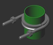
Of course, I'm having a few issues that I need to work out. Firstly, of course, the hose clamps are insufficient for the full power. The foot tends to torque itself crooked to the point that the chain slacks and falls off. I will need to prevent this from occurring - some sort of friction material between the drive foot and the bosses on the frame should work. The T-bolt clamps should be able to hold everything together with sufficient force.

The chain tensioner is actually a lot quieter while riding than I would have thought. Although it's such a piece of crap I'd rather just replace it with a spring-loaded ball bearing one.

I have the CC controller cutoff at 31.8v, effectively limiting the current available. I logged a peak current of 81.2 amps, where voltage sagged to 30.8v. Once I get a rock solid mounting option I may lower the cutoff voltage to really see what this setup can do. But I'm really scared of blowing things up, so I may just nudge it down to 30v.

What's odd is the 10 awg coming out of the controller gets slightly warm after a few launches, while my 10 awg wire doesn't. I might replace their wire, but that's going to be extremely hard to solder, so I might just accept it. After all I'm not going to be doing full power launches constantly, I'm going to be commuting. :D

So yeah. I'd say today was a very successful day and I am very pleased with the results. I will post a video in the coming days to show it off!
 
Clamps slip on round tube, why not bolt drive through the tube? the amount of torque these motor/drive have
i think it would be sensible to do this way rather than clamps alone?.
The clamping of drive concerned me when reading through the High power RC motor and drive unit production thread. I thought
when reading about the methods to attach that clamping was not so good way to do it just simple and adaptable for the majority i think?

Good to hear you have working you are officially the first now i think aside from recumpence himself i mean hehe
 
Hi Oofnik,

Glad its running :D :D :!:

Is the foot in contact with the frame tube or is it resting on the bosses? If its on the bosses it might be a good idea to drill a couple of small holes in the bottom of the foot so that the foot rests on the frame.
 
Man, that is so cool! I am thrilled you have it up and running!

I would recommend not pulling more than 80 amps out of your controller for safety sake.

Do you still have my number? You should give me a ring and come by soon. Hmm, it would be good if you could get your bike on the train to bring it up to me. Making some CNC frame clamps takes a long time. But, I could easily help you with aligning the drive with your water bottle holes as slip eliminating locating holes. :D

Matt
 
Here is a brace idea that would keep the foot from kicking out. I think you could make it with simple hand tools. Keep the hose clamps where they are. The diagram is ugly, but the brace would be pretty.

Bubba
b1.JPG
 
Hi Oofnik,

Kudos on getting it running 8) hope you get the clamp situation sorted out, it's causing us all some problems tbh.
Video in action would be awesome, i watched your test and couldn't help but smile seeing that little drive run up like a champ.
Thanks for the discription of the test ride, tells me we're on to a winner here :mrgreen:

Cheers,

D
 
Most definitely a winner. Thank you everyone :mrgreen:
My t-bolt clamps should be coming in soon, so I will replace the worm gear clamps with those. And Mitch, I was thinking about doing exactly what you suggested actually. If I drill two countersunk holes the diameter of the water bottle bosses, the drive can fit right into them. That with the combination of the hose clamps wouldn't let it go anywhere.
Maybe I can even put two cap screws in to the bosses and mill out the diameter so that the entire head fits in to it. Bubba's idea would work well too, but this way would require less parts.

In other news I got my BMS and 400W charger I ordered from E-citypower. They built me a custom 80 amp BMS so I will be testing the balancing and cut-off features extensively in the coming days.
 
Thought you all might want to see the carnage :twisted:
IMG_4640_640.JPG
The point of failure will be eliminated with the T-bolt clamps.

Also, here's my anti-torsion solution:
IMG_4641_640.JPG

I'm going to mill two slots maybe 1/8" deep, 3/4" long in the bottom of the foot that will rest against the top of the cap screws. This together with the updated clamps should prevent any movement whatsoever even under full power. At least, that's what I'm hoping. :mrgreen:

I'll either do the milling with Matt (I'll be calling you in the next few days... school work...) or at our school garage if I can get machine time (about 2% likely).
 
Cool.

We should mill the slots deeper than that....... maybe the depth of the screw heads. Bring those screw with. We can mill teh slots to be a relatively slop free fit.

Matt
 
Yeah, I was just worried about clearing the existing holes, but I guess it's okay if we go in to those at the ends.

I'll show you guys what I'm working on now until I get the new hose clamps in:
IMG_4651_640.JPG

Got a slick box for $0.47 (yes, 47 cents) at Sears. The latch is broken so I'm going to go pick up two draw bolt latches for a few bucks at the hardware store later and it should be good to go. I plan on sealing the perimeter to make it all watertight. Not like I'm going to leave my ebike out in the rain for extended periods of time, but, you know...

IMG_4650_640.JPG
Here's the innards rat's nest of my electronics box. Inside is the Castle ESC with an external heatsink mounted, the servo tester, the EagleTree data logger, and a USB dongle to connect up to my computer to download the data. The servo tester input and logger LCD leads are wired to an RJ 45 (ethernet) jack which sticks out of the box. I'm sending the signal over a cat 5 cable to the handle bars. I wanted to make the entire electronics unit quickly removable and this is the best way I could think of doing it.


And the innards of the battery case, open and charging. Sure is a tight fit with four different kinds of foam! :p


I need now to figure out a mounting system for the case to the top of my bike rack. It has to be strong and easily removable. Bungee cords won't cut it for the long run. Hmmm...
 
Hi Oofnik,

I like the boxes. Nice job!

I think you can make the combination of the foot fitting over the screws/bosses and the stronger clamps work. Would slots be better than holes so you could slide the mount for chain tension?

I also think the difficulty of using U-bolts instead of stronger clamps will be about the same and the results will probably be stronger.

If I remember correctly the issue was the angle not fitting the entire length of the foot. I have some ideas you might want to consider.
Use a length of angle stock or bar (if you don't like the winged look). For fitting:
I think Matt might be willing to grind it down to fit, it sounds like a trivial job (offer to buy him a nice lunch).

If not I bet you can find someone who does metal work who will do it for a nominal fee. Something like someone who advertises for Body Work or Welding on Craigslist.

I think you can use two short pieces (front and rear), for mounts, on each side of the foot to avoid the interference. A problem is that the U-bolts will cause the pieces to rotate around their mount bolt on the foot. Three possible solutions are:
1. Use two U-bolts on each piece, on either side of the foot mount bolt.
2. Fasten the U-bolts to the pieces exactly inline with the foot mount bolts.
3. Use a third piece of aluminum, like a bridge to tie the pieces together. There might be a size or shape of material with the required strength that will bridge the gap without interference.
 
Hey Mitch, thanks :)
I feel like the U-bolt solution is more trouble than it's worth. Although it would be stronger, there are some advantages to using the hose clamps: they are flat, so they have a much higher surface area against the frame, they require less parts, and they require less work. So I think I will stick with the hose clamps for now.

I did indeed plan on milling slots instead of holes for exactly that reason.


Oh yeah, I came up with a solution for the monstrous spark upon connecting the drive. All I need to do is get some nichrome wire, wind it in to a spring, and stick it in to one of the male connectors between the battery and the electronics box. I connect one terminal first, then the second terminal with the nichrome spring in it second. The initial contact through the resistive spring will allow the capacitors to charge up at a lower current, hopefully low enough such that a spark won't occur. Once it's up to voltage (shouldn't take more than a second), the connector is fully inserted for the full current to flow. I don't have any nichrome wire at the moment so I can't test this idea out, but I plan on stopping by the hardware store tomorrow.

What do you guys think?

And some more pictures:

Electronics on bike
IMG_4652_640.JPG

the "console"
IMG_4654_640.JPG


I still have a bit more to go - hose clamps, slot milling, actually screwing the electronics down on to the battery case, etc. But this is pretty much it.
 
Hi,

oofnik said:
Oh yeah, I came up with a solution for the monstrous spark upon connecting the drive. All I need to do is get some nichrome wire, wind it in to a spring, and stick it in to one of the male connectors between the battery and the electronics box. I connect one terminal first, then the second terminal with the nichrome spring in it second. The initial contact through the resistive spring will allow the capacitors to charge up at a lower current, hopefully low enough such that a spark won't occur. Once it's up to voltage (shouldn't take more than a second), the connector is fully inserted for the full current to flow. I don't have any nichrome wire at the moment so I can't test this idea out, but I plan on stopping by the hardware store tomorrow.

What do you guys think?

Does this help:
http://endless-sphere.com/forums/viewtopic.php?f=16&t=7994
preventing sparking when connecting battery and controller
 
Back
Top