Internal Resistance for pack of LG HG2 cells

garolittle

10 kW
Joined
Mar 3, 2018
Messages
509
Location
Augusta, GA U.S.A
Background: I have a 14S/20P pack of LG HG2 cells and need to measure the internal resistance of each cell string. Can I use the process discussed at the 4-minute mark of the YouTube link below except use a 20-olm resistor instead of a 1-olm resistor? Thanks!

https://youtu.be/av38iBxcOgQ
 
To be clear, you want to measure the resistance of each 14S1P string? Or each 1S20P group? Not sure how your pack is configured. Basically, you can estimate current using I = V/R. I usually use 2C current for measuring DC resistance. If your current is too low, the voltage drop is too low and your accuracy isn't great. Obviously you don't want the current to be too high for your test equipment either.
 
PaulD said:
To be clear, you want to measure the resistance of each 14S1P string? Or each 1S20P group? Not sure how your pack is configured.

My apologies. Since the 20 in parallel act as a single cell in terms of voltage, I want to measure the internal resistance of each sting of 20
 
docware said:
garolittle,what is purpose of this pack measurement ?

I want to verify the BMS data regarding the internal resistance. I have an Orion jr. BMS and it is showing a higher reading than normal. Typical IR for this pack has been .8 to .9 but the recent reading was 2.8.
 

Attachments

  • DF2C1EDD-7C7C-480B-8910-C0C346EFA53A.jpeg
    DF2C1EDD-7C7C-480B-8910-C0C346EFA53A.jpeg
    90.6 KB · Views: 1,802
Measurement on the video has an error about 30 %. New fresh LG HG2 cell should have about 21 - 22 miliohm at 25 °C and 3,85 V, at 4 V may be even little bit higher. I assume that such accuracy is not acceptable for you.
 
Got an idea. If you can measure charging current or if you know the charging current, you can calculate internal resistance from the charging current value and voltage difference on the cell. You just need to have DMM with resolution mV or better 0,1 mV and connect to any cell´s balance wiring.
 
docware said:
Got an idea. If you can measure charging current or if you know the charging current, you can calculate internal resistance from the charging current value and voltage difference on the cell. You just need to have DMM with resolution mV or better 0,1 mV and connect to any cell´s balance wiring.

Hey Sir. Thanks for the great responses. I will try your idea and let you know the results. I have to show my ignorance now ..... What is “DMM”. Also, in the screenshot above, what does 2.81 mean? Miliolms? It is normally .8 - .9. I could not find the unit of measure in the Orion JR manual. Thanks again for all of your help.
 
DMM is a Digital Multi-Meter

Getting IR for benchmarking changes from now vs later is very useful.

However, requires using the same calibrated instrumentation, voltage delta, current levels, SoC and temperature in order to be usefully comparable.

In theory it's a single number, but

______
In theory there is no difference between theory and practice. In practice there is.
— Yogi Berra

 
Yes, as john61ct mentioned, tracing of the internal resistance is useful, however requires using still the same conditions (temperature, SOC) and method. Using precise equipment is a must.

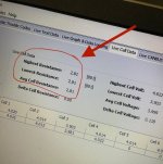
2,81 probably means miliohms, 20p LG HG2 should have about 1 miliohm per one paralel group (new fresh cells). Values 0,8 – 0,9 are telling us that inaccuracy of this BMS measurement was 10 – 20 %.

If you want to copy resistor method from video, you need to get at least 1A per cell which is 20A total. 4 V per cell means 56 V total for 14s battery. To get 20 A you need precise resistor 2,8 Ohm, power dissipated on resistor would be 1 120 W !!! Moreover, as temperature of the resistor will go up, the resistance will go up also and real current will be smaller. That is one reason of inaccuracy on the video, unsufficient DMM resolution is another, unsufficient resistor accuracy another, ………

As 1 kW precise cooled resistor is little bit a problem, I suggested method of cell´s voltage difference measurement during charging. I assume that charging current is about 1A per cell.

Resulting accuracy will depends on the current measurement accuracy and voltmeter resolution.
Even if total inaccuracy will be suppose 10 – 20 %, for checking of sudden 300 % rise of IR measurement such method could be sufficient.
Maybe you can borrow DMM with enough resolution and clamp meter or precise shunt for current mesurement.
 
Remember, this is a “group” of 20 cells in parallel.
Whilst they stay connected in parallel, you cannot get any IR data for individual cells...only the “group” result
And that can be affected by many other things such as connection integrity (40+ connections per group !) and individual bad cells corrupting the results of measurements
 
We are not speaking about IR for idividual cells. garolittle wants to verify BMS internal resistance measurement, because it is showing 3 x higher readig than normal.
 
I really appreciate all of the responses. I have learned many things and will use the “charger method” references above. Good point about the individual cells. Also, it is true I am only looking for the IR of the cell string (with 20 in parallel). Either way, I appreciate the responses from both of you. Gary
 
Cells connected in parallel can be referred to as a Group

A String always refers to cells or groups connected in **series**

Bank is the highest level, usually a fixed location or tied to a boat or vehicle, at a specific useful/standard voltage, for some reason often not used for propulsion use cases.

"Pack" is widely used for EV / propulsion, can be like "modules" as a physical unit, but can also signify the whole bank, so I generally avoid if that makes things ambiguous. But, OK to use packs to mean "portable bank", as in powerpak, and also "pack-level" charging rather than bulk charging, to distinguish from balance charging or node-style charging via cell-level balance leads.

I use "Modules" for standalone functional units
usually portable, physically self-contained
at a specific useful/standard voltage
usually can be used / charged separately
and/or wired in series or parallel to comprise
the main bank, even rotated in and out

Otherwise sub-banks or sub-packs, when xPyS units are further joined in parallel or series to comprise the full Bank or Pack.
 
garolittle said:
I really appreciate all of the responses. I have learned many things and will use the “charger method” references above. Good point about the individual cells. Also, it is true I am only looking for the IR of the cell string (with 20 in parallel). Either way, I appreciate the responses from both of you. Gary

Let us know the outcome Gary.
 
docware said:
Got an idea. If you can measure charging current or if you know the charging current, you can calculate internal resistance from the charging current value and voltage difference on the cell. You just need to have DMM with resolution mV or better 0,1 mV and connect to any cell´s balance wiring.

So my DMM is very basic. See below. Any recommendations for a good one I can buy to perform this test? Thanks.

 
Hmm interesting. I've thought of using potting compound that is thermally conductive with aluminum shell.

But phase changing sure takes things to another level.

Of course best practice is to prevent heat from rising significantly, but some people / use cases just require /accept that.
 
Ok. Part of the mystery was solved. When I use the OrionJr. BMS “Setup Wizard”, I have to select a battery type. Since the LG HG2 was not listed, I chose the other LG cell. That is what caused the “2.81” reading for Internal Resistance”. Last night, I changed it to the Panasonic cell and the reading returned to a more normal IR reading of .96. Apparently, the LC cell that I selected previously was a different chemistry.
3DD5DBFA-3B14-4269-A703-B8AA4FF829A6.png
 
What does the BMS use those data for?

I'm surprised it doesn't read them directly in order to tell the user, rather than the other way around.

Do they update the "library" as new cells come on the market?
 
Back
Top