Parallel "Groups" or Parallel Strings or Neither ?

john61ct said:
Sorry as I said, I think need to visualize with wires only, I've looked at thousands of these plate / strip pictures and I just don't grok the both-together concepts that way.

So I'm hoping someone can draw a diagram that uses wires to replicate this weird layout y'all use with strip/plates.
That's the point of the plates--wires can't do what they do, which is make a large-area conductor plate that doesn't have interconnection points between them.

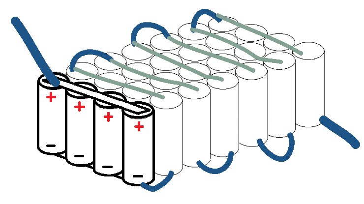
If you want to replicate this common (not wierd) connection method with wires, you'd have to lace the wires into a braid that looks like solderwick, but in a big flat "plate"--but it still isn't the same, resistance-wise, as the plate.

Electrically, it's the same whetehr using wires or plates or strips, you're paralleling cells, and seriesing them to toher paralleled cells.

The grid-connection using spotwelded strips, shown in the pic below, in your quote, is electically the same as using a plate to do the same thing.

> Here is a pic showing the series current-flow of 25A through a common 5P pack.
Battery186508.png


Well there's no way to see which cells are positive end up and which negative
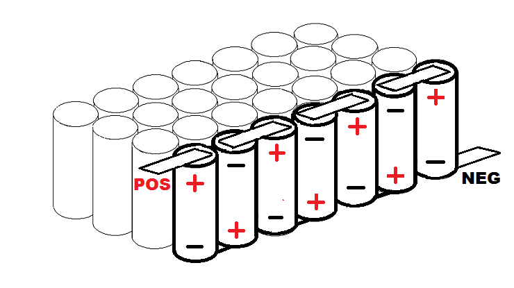
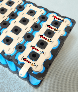
Assuming those are common 18650 cells, then sure there is. You can clearly see that the cells on the rigth of the arrows are the large flat ends, whcih are usually negative. The ones on the left of the arrows (where the arrows are pointing) are visibly buttons with a gap between them and the insulating ring / outer heatshrink.

But it doesn't matter what direction the arrows point, the diagram is simply showing that the current flows serially from one cell to the next, and is not flowing along the parallel connection. If it had to flow across teh parallel connection first, to get to one of the series connections, it would be higher resistance along some paths than others, so unequal current distribution. But in this "grid" method,current flows the same to/from all cells.


If so then that's bog standard to me, the weird bit (for me), is the idea of an individual cell being connected to other cells in more than one way at a time.
That's exactly what happens in all the packs that use parallel groups of cells that are then connected in series, regardless of how you do it, electrically.

Resistance of the paths from one to the next are the only significant electrical differences between the connection methods. (the only difference applicable to it being a battery, anyway).
 
amberwolf said:
common (not wierd)
Obviously tongue in cheek, only common with these tiny cylinders though, certainly wierd to those who've only worked with bolts / posts and insulated wiring with crimped ring terminators, 00 AWG being a small gauge, 60Ah being a small single cell.

amberwolf said:
If you want to replicate this connection method with wires, you'd have to lace the wires into a braid that looks like solderwick
I think 2 or 3 wires per post, fatter ones going "forwards" to the serial neighbor, and thinner ones for the "sideways" within the group, would do it.

Resistance could be matched with fat enough gauge - not advocating, just sayin'.

OK, so from the bottom (right), row1 is negative up, as are all the odd rows, and all the even rows are positive up?

So a corresponding grid/plate is connecting every other pair of rows underneath, where they are "missing" up top?

Your help, again is greatly appreciated.

 
OK, was wondering if the previous sound track (now deleted) would bring everyone up short and give this thread a ... r.e.s.t ... so waiting until now to delete and re-record (and re-edit) today (12/12) ... objective accomplished.

Do grasp/understand S/P wiring basics that amberwolf, john, spinningmagnets and others think not of me or at least question and in their mind for good reason? As Les Paul would say, "He nailed me to the wall" when referring to Charlie Christian's jazz guitar fingering technicals.

A couple questions/comments were really stupid mistakes that i wish i would've caught and re~corded before posting ... when i knew better. Some of the other questions weren't all that stupid from the standpoint that there's no such thing as a stupid question. Anyway, the informative rebuking replies were necessary for my own confirmation and for any luriking guests along their S/P learning curve ... as we're all learning worthwhile lessons in one way or another :wink:
 
Now that i've deleted and entirely revised my above post the following may be of some worthwhile value to discuss further ...

The first two posts by amberwolf and john61ct (at the top of this page) are worth reading and re-reading again and again to digest the content. First-off as john rightly says we may visualize these S/P connections differently whether triangular pack, rectangular pack or otherwise (whether right or wrong). Sometimes both may mean the same; while expressing it to another in what may come across as the wrong "tone" or confusing.

At this stage my DIY pack "tone" (e.g. raw performance / longevity of Les Paul) doesn't come close to either amberwolf or john's DIY pack buiding technicals. Such as Charlie Christian's jazz guitar technicals that in a manner of speaking ... "nailed Les Paul to the wall" while the two were jamming at the Cotton Club in Harlem.

So, getting back to a comment that spinningmagnets made on another thread relative to the first two posts on this page leave me with at least a couple related spot~welding (and parallel fuse soldering) questions hanging and possibly too debateable to discuss further ...

Question One: What DIY pack size (not powerwall) and its application are best served with the use of parallel fusing?
Question Two: Should DIY pack S/P negative cell end connections be sized differently than positive end connections?

Question Two is with respect to thunderhearts (and docware's?) method of testing 18650 cells ... https://ic.pics.livejournal.com/thunderheartrev/71546108/209931/209931_original.jpg ... now if only both amberwolf and john can answer these questions in layman's terms that even a newbie DIY guest and myself can get ahold on ... or perhaps debateable electrical theory, but still a worthwhile discussion :thumb:

For any youngsters that don't know who Les Paul is or have never seen youtubes of him jamming at the Iridium Jazz Club (into his 90s) ... https://www.youtube.com/watch?v=0IOBVTdHZiw ... just have to say it was never my intention to ever "play a note in bad taste" on this S/P thread or any ES thread.
 
I think for simplicity and thread hygiene better to just start a new thread for each question.

Lay out what you actually want to accomplish, as specifically as possible.

Ideally with diagrams.

Do not embed complex assumptions into your question that may or may not be true.

Lay off the jazz analogies, never mind about past errors or your feelings.

Don't bother editing past posts, just let such threads die and start anew phrasing your new topic questions better based on your growing understanding.

______
> What DIY pack size (not powerwall) and its application are best served with the use of parallel fusing?

DIY or not has nothing to do with it.

Size is not really relevant.

Do you mean paralleling multiple packs together? If not, then do you mean paralleling cells to form the 1S groups at the lowest level of a pack?

Again a drawing would help understand your use case.

Most packs only put fuses (if any) on the main power wire.

Internally I've seen fusible links as with Tesla packs, but those are used on a per-cell basis.

______
> Should DIY pack S/P negative cell end connections be sized differently than positive end connections?

In general, my answer is no.

I would phrase it: Why does this example testing rig have different sizing for positive vs negative?
 
Dearest John,

In case you hadn't noticed it wasn't you who started this S/P thread. Besides i already believe i know the answer to my two relatedf S/P questions and was curious to see how either you or amberwolf might reply.

Actually our reply is no surprise and to be expected as you've never wanted to answer one of my questions, but rather rebuke/demean me in one way or another. Like previously mentioned you as much to discredit yourself as discrediting me. Not by what you know or don't know, but rather by your bad notes.

Amberwolf you'd better digest john's post and not reply to either of my latest two S/P related questions as this S/P thread has apparently run it's course. So PLEASE don't further this thread by replying to any more of my stupid questions. Frankly, i doubt john will ever get it as he's so into himself.

With all the time john spends posting on ES threads with his frequent posts and his DIY expertise why is it he's not a moderator at ES

Yours truly,
Chalk
 
Dearest John,

I threw in the Les Paul / Charlie Christian S/P analogy should U not find anything else to fault :thumb:
but wouldn't you know it that john was able to find more than one fault :thumb:

Yours Truly,
Chalk (it up)
 
Getting good answers requires asking the right questions.

I do not intend to disparage you in any way. I am spending my time genuinely trying to help you get the information and knowledge you seek.

I learn lots of new things every day, but it does take a pretty thick skin, not getting butt hurt every time someone corrects me.
 
This top picture is the series current. The pathways shown connecting the cells flow the highest amps that the pack is capable of (compared to the parallel current). "IF" you are using 30A cells and actually drawing that much as a temporary peak once in a while, then each 7S string will be flowing 30A. Since there are four series "strings", then 30A per string means that the entire pack will be able to provide 120A peaks.

BatteryPack4.png


These are the parallel connections in the pic below. If all four cells "per group" have the same internal resistance, and all of the connecting strips have the same quality of connection and resistance, then the parallel connections between the four cells should not see very much current at all. Most certainly less than one amp under all conditions.

The more resistance you have between each cell in the parallel connections, the slower they will equalize, but...a slow equalization is good. If you are pulling 30A from all four cells in the group, one cell might provide a little more, and another cell might provide a little less. So, after a few seconds of hard acceleration, you drop back to a low-amp cruise-phase. At that time, the four cells will slowly equalize to the same voltage.

Since they started out at the exact same voltage, the temporary variation in voltage will be tiny. This means the equalization current across the parallel strips (or buses, or plates) would likely be measured in milliamps.

BatteryPack3.png
 
Single string pack example


Each group, A to G, is composed of four cells connected in parallel.

Then in turn, each group is connected, as a whole, to the next one in series, to create a single 4P7S string, which in this case also comprises the pack.

A+ is the pack-level positive terminal.
A- connects to B+
B- to C+, C- to D+ … F- to G+
and G- is the pack-level negative terminal.


a5620d4a5662ada1db95286667a734ec.jpg


sorry so crude
467cc21f132feb4a56da407fd607793f.jpg


I realize physically in a spotwelded eBike pack, you could have just a single plate make each of the 2-group connections, both serial and parallel at the same time.

But since I'm used to using insulated wires, it is much easier to visualize the logical flow-path that way, and maintain the "grouped in parallel first, then groups connected in serial" concept mentally.

In addition, my plans for weld-less/solder-free pack construction, or using pouches / prismatic cells, may well continue to use wires.
 
john61ct said:
Single string pack example ... to create a single 4P7S string, which in this case also comprises the pack
Or another way of expressing "a single 4P7S string" as a "meandering string" that you previoously mocked/ridiculed as a stupid comparison. To be completely honest you seem preoccupied with always trying to find fault if it isn't according to your electricsl theology. Even when a "meandering" single string is an apt description which i visualized early on before sp's excellent post with diagrams and your repetitive reply.

Spinningmagnets would never demean or ridicule me for visualizing "a single 4P7S string" as a meandering string, even if he didn't visualize the single string as meandering. The reason i choose "meandering" is because like flowing water whether flowing straight, zigzaging, winding, twisting, or taking 90 degree turns so too electrical current flows through the connecting busbars whether straight, taking 90 degree turns or otherwise meandering like a river.

At least spinningmagnets agreed with me that these diagrams are 3S4P ... http://endless-sphere.com/forums/download/file.php?id=98636 ... whereas at the time you weren't sure until spinningmagnets confirmed that they are 3S4P. So, now you'll probably say that you knew all the time as it was so obvious you thought my question was an insult to your S/P IQ. How a single string meanders in a pack is entirely up to the DIY builder ... https://endless-sphere.com/forums/download/file.php?id=262218

Ok, now it's your turn to find something in my post that you can mock or otherwise find fault with :thumb:
 
Prolly more productive for us to just focus on substantive issues now that we understand each other better.

Feel free to just ignore my posts if you prefer. There is I believe a feature of the forum software where you could just make them invisible if that gives you better peace of mind.

I was / am just trying to be constructive, to keep learning myself and trying to help others along the way.
 
eMark said:
john61ct said:
Single string pack example ... to create a single 4P7S string, which in this case also comprises the pack
Or another way of expressing "a single 4P7S string" as a "meandering string" that you previoously mocked/ridiculed as a stupid comparison. To be completely honest you seem preoccupied with always trying to find fault if it isn't according to your electricsl theology. Even when a "meandering" single string is an apt description which i visualized early on before sp's excellent post with diagrams and your repetitive reply.

Spinningmagnets would never demean or ridicule me for visualizing "a single 4P7S string" as a meandering string, even if he didn't visualize the single string as meandering. The reason i choose "meandering" is because like flowing water whether flowing straight, zigzaging, winding, twisting, or taking 90 degree turns so too electrical current flows through the connecting busbars whether straight, taking 90 degree turns or otherwise meandering like a river.

At least spinningmagnets agreed with me that these diagrams are 3S4P ... http://endless-sphere.com/forums/download/file.php?id=98636 ... whereas at the time you weren't sure until spinningmagnets confirmed that they are 3S4P. So, now you'll probably say that you knew all the time as it was so obvious you thought my question was an insult to your S/P IQ. How a single string meanders in a pack is entirely up to the DIY builder ... https://endless-sphere.com/forums/download/file.php?id=262218

Ok, now it's your turn to find something in my post that you can mock or otherwise find fault with :thumb:


Wow this guy single handedly hijacked a really good thread and scared away the talent, seemingly because his "Fe-Fe's" were hurt?! And somehow this is being tolerated?

eMark, you sound like the type of guy who talks allot (mostly to himself) and drinks soup out of a flask. This was an informative thread before you gunked it up with your cringe worthy, beatnik, boomer references. Nobody cares. Post less and read more.
 
Now that I know that you intend to solder wires to the cell ends, you can place the series/parallel wire tips side-by-side. The reason I rambled on about the option of series first to reduce resistance, is because many builders are using full-width nickel ribbon as a bus material, and it contacts the entire cell-end.

If doing that, you have no choice but to do one or the other first, and then overlay the last connection. In that scenario, clearly "parallel first" (which is common) does work, and for low-amp applications, there is really no performance penalty.

I only meant to point out that for high-amp applications where you are encountering excessive voltage drop and you are using 8mm-wide nickel ribbon, its a fairly easy and expensive change to attach series first. (of course, at the moment of pack assembly, all cells should be at the same voltage, within 0.1V or less)

As a side-note, the positive tips of 18650 cells are quite robust and they can easily stand a quick soldering job (high heat, fat soldering iron tip for thermal mass, short duration). However, the negative end is much more sensitive to heat damage. If your soldering methods damage one or more cells, it will be on the negative end of a cell...
 
spinningmagnets said:
Now that I know that you intend to solder wires to the cell ends, you can place the series/parallel wire tips side-by-side.
Who are you referring to? Can't seem to locate that post in this S/P thread by another member? So, being Ron has decided to change the intent of this thread (?derail?) i will oblige spinningmagnets with only the best of intentions for clarification to Ron.

When soldering of leads from a decent smart BMS onto a spot-weld pack the soldering of the leads is done after the the series busbar spotwelding NOT before directly on the cell end (sometimes half-between busbar ends). The exception is with fuse wiring when soldering is done directly on the cell end (preferrably button cell).

Fuse wiring is not necessary for my provision with [Series] bottom balance charging (when needed) before bulk charging instead of just idle top balancing with most all BMSs which can take hours or even days with an aged pack having unbalanced cells. Thus the reason why Tesla favored bottom balance charging instead of top idle balancing (i.e. ebiking BMS packs).

Because i'm using a non spotwelded Vruzend kit with my own provision for balance charging ... fuse wiring is overkill. Instead the balance charging lead connections are secured between cell end connectors and series busbar connections. No soldering is necessary. That was one advantage (no cell end soldering) that sp liked about No Weld/No Solder kits (e.g. Nishi (non spotwelded) kit :thumb:
st35326 said:
Wow this guy single handedly hijacked a really good thread and scared away the talent, seemingly because his "Fe-Fe's" were hurt?! And somehow this is being tolerated?
Alll of my OP posts up until Ron's were about Series and Parallel wiring. If anything Ron supported my String rationale when at first john was trashing both Ron's previous posted understanding as well as mine of a Series String. Then when Ron posted his understanding of a Series String (same as mine) on this thread john immediately starts talking out of the other side of his mouth agreeing with Ron and in affect also agreeing with my understanding of a Series String.

John likes to trash me with disinformation and misinformation thinking it makes him look better. It all goes back to my "Plz Xpln" to john too which he apparently still has an axe to grind. So, now i just say something like "OK, john time again for you to bad-mouth me." :thumb:
 
At this point, best I can say is, do what you like.

At no time have I done anything but try to help you understand.

Between the incoherence and invented interpersonal drama engaging further here is just not productive.

Please just leave me out of it.
 
spinningmagnets said:
Now that I know that you intend to solder wires to the cell ends, you can place the series/parallel wire tips side-by-side.
Still don't know how you thought that i intended to solder fuse wires to the ends" of my Vruzend pack cells. You still didn't answer either of my two questions about that previous post?? Here is that post where you thought i was going to solder fuse wires to my Vruzend pack. Even more confusing after you had read my last reply on your Tesla style fuse wire thread. Here is the post that spinningmagnets misinterpreted. Apparently the two questions are "too debateable" for sp to answer. That's why i asked them as there isn't an easy answer and now we know they are too debateable to arrive at any number of S-string or P-group consensus.

eMark said:
So, getting back to a comment that spinningmagnets made on another thread relative to the first two posts on this page leave me with at least a couple related spot~welding (and parallel fuse soldering) questions hanging and possibly too debateable to discuss further ...

Question One: What DIY pack size (not powerwall) and its application are best served with the use of parallel fusing?
Question Two: Should DIY pack S/P negative cell end connections (busbars) be sized differently than positive end busbar connections?
Question Two is with respect to thunderhearts (and docware's?) method of testing 18650 cells ... https://ic.pics.livejournal.com/thunderheartrev/71546108/209931/209931_original.jpg ... now if only both amberwolf and john can answer these questions in layman's terms that even a newbie DIY guest and myself can get ahold on ... or perhaps [too] debateable electrical theory, but [perhaps] still a worthwhile discussion :thumb:
john61ct said:
Please just leave me out of it.
I glady will if you stop/desist from replying to my posts with disparging comment that actually does as much to discredit you in your attempt to discredit me often with disinformation and misinformation. Besides you said you were going to ignore my posts and yet here you are again. So, i will no longer mention your name unless you provide disparaging remarks (i.e. misinterpretation) with respect to my posts.

Have purposely spend considerably more time preparing my replies before posting and even then editing because i know you are looking for any opportunity to find fault even when you had to resort to disinformation and misinterpretation. And apparently all because of my "Plz Xpln" a few months ago which apparently you interpreted as an insult and hurt your feelings ... lighten-up!! From now on just ignore my posts and i will gladly refrain from commenting/quoting any of your misrepresentations :thumb:
 
Now, there is an advantage to wiring as no parallel cells: one bad cell can't take down al the ones in parallel with it. HOwever: that one bad cell will, if not monitored, instead destroy the series string it is part of, because every other cell in it will be overcharged by the voltage of the pack divided by the number of series cells, minus the one that's internally shorted. The other possible failure mode of an internally shorted cell, related to the above but while riding instead of charging, is that the series string it's in drops a cell's worth, and then the strings paralleled to that drain into the string with a problem. How far they drain, is dependent on the number of cells in series vs the one that shorted. If the pack was full when it happened, it'll also be overcharging the other cells in series with the one that shorted.

that's the question ive been wondering, if you have 2-16s4p packs connected in parallel, no bms no fuse. and 1 group of p's goes down in 1 pack, does the good battery pack attack the bad battery pack?
 
Good to edit quotes, but do please leave the meta info, especially the author you are quoting.

amberwolf said:
Now, there is an advantage to wiring as no parallel cells: one bad cell can't take down al the ones in parallel with it. HOwever: that one bad cell will, if not monitored, instead destroy the series string it is part of, because every other cell in it will be overcharged by the voltage of the pack divided by the number of series cells, minus the one that's internally shorted. The other possible failure mode of an internally shorted cell, related to the above but while riding instead of charging, is that the series string it's in drops a cell's worth, and then the strings paralleled to that drain into the string with a problem. How far they drain, is dependent on the number of cells in series vs the one that shorted. If the pack was full when it happened, it'll also be overcharging the other cells in series with the one that shorted.

goatman said:
that's the question ive been wondering, if you have 2-16s4p packs connected in parallel, no bms no fuse. and 1 group of p's goes down in 1 pack, does the good battery pack attack the bad battery pack?

There is of course no "attacking" going on.

But yes, the lower voltage of the sub-pack gone bad, pulls lots of current from the good one until they are at equal voltage.

IOW you need a protective circuit designed to isolate the two sub-packs as soon as there is a substantial voltage difference between them.

A Victron BMV-712 has that ability, just as an example.
 
john61, I wasn't sure about the quotation thing, amberwolfs response was very long covering many things so I just grabbed that paragraph. heres why.
I have 2-14s4p packs, all good cells, I had another with some questionable cells and 1 of the p groups was wiped out because of 1 cell, so I made 4-14s1p and paralleled the ends but now I want to take half of that pack to make my 2-14s4p into 2-18s4p. I know the crap pack had atleast 28 good but I need 32 cells maybe ill just do 2-17s4p instead and use the questionable cells on something else and 4 good spares.
 
goatman said:
if you have 2-16s4p packs connected in parallel, no bms no fuse. and 1 group of p's goes down in 1 pack, does the good battery pack attack the bad battery pack?
Why NO BMS and Why NO pack fuse and Why NO parallel cell level fuse wires? Apparently you didn't even have a provision for bottom balance charging before bulk charging? If that is true (not even provision for balance charging) do you realize that your DIY pack design is about as BIG of a NO NO NO as exists in DIY 18650 pack building design?

Spinningmagnets previous post relative to cell positive end fuse wire soldering is a reference to my previous question about parallel cell level fusing (i'm not an advocate of fuse wire soldering onto the cell end AND new button-top 18650 cells are usually more expensive than flat top ~ also ALMOST ALL of the photos and youtube videos on cell end fuse wire soldering is because the DIYer is using salvaged 18650 cells (inexpensive) which necessiate extra protecton as salvaged cells differ slightly in mAh capacity.

So here is my previous question which no one has yet been able to figure out so will now reply to my own question as your 2-16S4P packs size is most applicable when one P cell is on each side of the two large 16 Series Strings. That's what i was getting at in that previous question (e.g. 16S4P ~ even moreso with salvaged cells without equal capacity) ...

What DIY pack size (not powerwall) and its application are best served with the use of parallel fusing?

First-Off all photos and youtubes of DIY packs with cell level fuse wires aren't (for example) a 10S5P or a 14S7P), but rather suited to your two 16S4P using CELL LEVEL FUSE WIRES with the two 16S strings and 4P (neither group or string) of mid-level cells of 3000mAh (e.g. class B (2900mAh).

Your two 16S4P rectangular packs in parallel is a perfect scenario for cell fuse wiring (ESPECIALLY WITH SALVAGED CELLS) to fuse wire each of the two single parallel cells (2P) on each side of your two large Series Strings running down the middle between one parallel cell (of your 4P pack) on each side of the two Series Strings. IN WHICH CASE YOU WOULDN'T CALL YOUR 4P A "GROUP" OR A "STRING" THUS THE REASON FOR "NEITHER" IN THE THREAD TITLE. However, no one caught on. Instead, one member saw it as an opportunity to quickly jump on my question as not making sense and belittle without taking time to adjust his thinking cap.
 
16s4p was just an example, im jumping upto 17s4p, the batteries iam using right now are 2-14s4p in parallel wired with a removable 14s 25amp bms I use for charging.
I play with different battery sizes so my 13s batteries have bms, 14s yes but not when on my bike, 2-15s5p I never balanced charged and after 3000km they were still balanced.

my 14s4p have 4-14g positive wires and 4-14g negative wires coming off the pack/ 1 for each P so I pull current straight through pack. then it all gets soldered into 1 positive and 1 negative

so when you talk about fusing a battery, what im hearing you say is on a 4p battery you would use two fuses going from 1s to 2s and you would place the fuses in between the 1p and 2p going to the 2s then 3p and 4p going to 2s. and if that is the case I could use only 2 positive wires and 2 negative wires coming off the battery but heavier gauge.

im curious how to protect battery pack A from battery pack B(paralleled) without using a bms while on the bike.

bottom balance, I did what I considered a bottom balance. when these cells were in a 2-14s5p with 2 bms wired I took all cells to 3.0v then I parallel charged both packs through a watt meter for 13 or 14 hours? at 2 amps 58.8 and the watt meter said 27ah. cant really remember exactly maybe the bms burned off 2 ah of the 25r packs but the meter said 27ah.
so my next build will be 2-17s4p and if I like it ill buy a couple bms. then ill worry about getting new higher quality batteries
 
goatman said:
with some questionable cells and 1 of the p groups was wiped out because of 1 cell, so I made 4-14s1p and paralleled the ends but now I want to take half of that pack to make my 2-14s4p into 2-18s4p. I know the crap pack had atleast 28 good but I need 32 cells maybe ill just do 2-17s4p instead and use the questionable cells on something else and 4 good spares.
With a good no-weld/solderless and convenient diagnostic gear, you could do your pack-breakdown plus go/no-go sorting as often as you like keep re-assembling "good enough" packs as often as you like.

But IMO it's just too much trouble, especially with spot-welding.

Better to start with a powerful pack of brand new cells, have some spares to replace weak links, otherwise they all wear pretty evenly.

When the pack as a whole starts to get to whatever SoH percent you decide means EoL, you save your pennies for the next brand new one, and at some point just retire the old one all at once.

Sure if you have a different low C-rate use case like phone chargers, flashlights whatever, then get a bit more life.

Or sell it to the tinkerers on eBay being honest, amazing what stuff goes for sometimes.


eMark said:
jump on my question as not making sense and belittle without taking time to adjust his thinking cap.
Wow.

Honestly curious what you are trying to communicate, not belittling at all.

eMark said:
when one P cell is on each side of the two large 16 Series Strings

with the two 16S strings and 4P (neither group or string)

Does **any** forum member have any idea what meaning eMark is trying to convey with this phrasing?

eMark, a 16s4p pack is usually just one string, 16 groups of 4. IOW put the 4 cells in parallel, then connect 16 of those in series.

There is no string, and then a separate group, it is one string OF groups, and there are no cells that is not in a 4P group, every cell is in a group,

and every group is in the string, IOW there is no group not included in the string, and all 64 cells are both part of a group then in turn included in the one overall string.

The way you are phrasing things causes me to think you still don't grok that concept.

> parallel fusing

Therefore I'm not even sure what you mean by that phrase.

Are you talking about putting 15 fuses in that 16s4p pack, one between each 4P group?

Or, if you mean fusing between two 16s4p packs, why use that as a design goal in the first place? hardly anyone even does that!

Most have no fusing at all. 99% of those that do, there is just one, right at the pack exit point, and it's there to protect the wiring against an accident, not part of the pack design.

Other members, please correct me if I'm wrong.

There aren't too many general rules about the various building & care techniques, each owner / builder may have their own beliefs & preferences.

Even with the new vs old cells factor!

Pack size is definitely not a relevant factor afaic.

Can't believe you still bring "rectangular" into it, can't imagine how you believe physical shape is relevant?

Same with "not Powerwall", what difference do you think that makes?

Same with odd numbered groups vs even numbered, just not a relevant factor afaik.

There is no "perfect scenario" for cell fuse wiring, it's just a preference for some 0.0001% of pack builders, not related to any of these factors.

Yes salvaged cells are more likely to fail, but that does not mean a perticular owner chooses a different design or even care approach for that reason. They just get a pack more likely to fail quickly, and are more likely to burn.

Which just means they should use new cells, or if they are poor, get a cheaper hobby.

This sort of word salad
eMark said:
each of the two single parallel cells (2P) on each side of your two large Series Strings running down the middle between one parallel cell (of your 4P pack) on each side of the two Series Strings
is simply impossible to respond to, completely incomprehensible, conveys zero meaning.

Just take one bit

> Strings running down the middle between one parallel cell

and make a schematic, simplified drawing to show what you think this means.

I am 99.99% sure two things are true

No other member here knows what you're trying to say, and

you are not understanding how this stuff works.

Sorry if you think I'm belittling you, that is not my intention.

I am trying to understand your words, translate them into the common phrasing used by everyone else, so that we can help you better understand the topic.
 
personally I wont sell one of my batteries, im just trying to get what I want out of my bike using the phaserunner so a pack that can do upto 60 amp burst, 30 amp continuous and 15 ah so I can parallel if I want 30ah with xt60 connectors. that's not hard for a battery but I don't want to have to keep buying a bms the phaserunner isn't quick to respond to the throttle, I think it slowly ramps? up, its fine in a 20 inch wheel at14s but not a 26 inch wheel, so im going to try to up the voltage, heatsink the phaserunner and I have enough good cells for 2-17s4p.
in all fairness to the phaserunner, I don't really know what im doing with it and its a pain in the ass getting the bike to the computer BUT grin just released an app for the smart phone, you can now plug your phone into the phaserunner and try different settings when out on the road, not on the fly, you stop make a change try it to see whats changed.

im so far off my original question I think im better off not paralleling but just having 2 batteries and when the one is dead, plug the other one in. someone suggested a bv720? cant remember but I googled it $260 usd or $400 Canadian pesos, maybe in the future but I cant afford that right now and then id just buy 2 good bms instead of a bv720? no?
 
Back
Top