XLD Brainpower motor controller XunLiDa

Hello,
Error 8 will be set by an sticky open or wrong connected Throttle.
Have you checked Throttle Operation Voltage with a Multimeter ?

mfg Martin
 
tlg said:
To enter the programming mode, you hold the "+" and "-" buttons down for a few seconds, and the display changes to the Programming mode. There are 20 settings that you can step through by pressing the Power button briefly.
I have listed the 20 settings below with Default, Range and Function.

Thank you for sharing!

Strangely enough, my XunLiDa only cycles from P0 to P4. I wonder where the missing settings are? I am trying to set the PAS mode.

On my controller, I get:

DISPLAY: XLD1808N
CONTROLLER: KSLU37

P0 31.5
P1 26
P2 045
P3 001
P4 0

Any idea why I only get 5 settings, after holding UP/DN a few seconds?
 
Posting here as some people with xld experience might know.

I bought this but it doesn’t recognize the PAS sensor.

https://www.amazon.com/gp/aw/d/B07T846V6L/ref=ya_aw_od_pi?ie=UTF8&psc=1


I know the pas sensor is working because it works on another controller but maybe it’s not the right voltage

The pas sensor when connected to the throttle connector does briefly power the bike to 8mph but it’s not fast enough so I do know the pas sensor is putting out a small voltage.
It’s a self enclosed Double hall sensor pas sensor with 10 steel magnets
View attachment 2

I can’t figure out what this blue screwed connector does It has 2 white wires.


564A6C54-813A-435A-BDB5-ED702A0F897E.jpeg


Thanks for any help.
 
I have one of those. 250W 48V and 13A. I set the voltage jumper on board so it will run on 36V.

The screw turns a blue potentiometer. It's suppossed to be for tuning speed, but mine doesn't do anthing, If rotated +/- 10 turns, the max no load speed reached with throttle doesn't appear to change.

The PAS sensor should not do anything on a throttle input. The signals are different.
 
Hello,
The Blue Trimmer shorts Throttle +Voltage to GND.
Throttle will also be affected by PAS Gear and Speed Limit.
As you use Model KSLU 58...
Reduces Output Power ,not speed at no Load,but an increase in Spin up time should be recognised.

mfg Martin
 
Roots Rocker said:
Hello,
The Blue Trimmer shorts Throttle +Voltage to GND.
Throttle will also be affected by PAS Gear and Speed Limit.

mfg Martin

Thanks. Counter clockwise all the way til it starts clicking,, I can cut the indicated speed from 20 mph to 14 mph.About 20 turns clockwise and I'm back at 20 mph,

I have a 20" wheel mounted, and using the indicated speed which depends on P3. I'd have to put a bike computer on and set P3 til I get the real speed,
 
philf said:
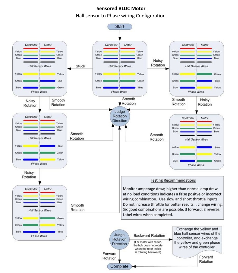
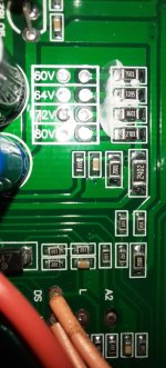
Anyways, I thought I toss this out there - the markings (and chip used) on this board seem to be very similar to the board posted earlier in the thread. I've mapped out where all of the coloured wires go, and what the do (though I have no idea how the "alarm" feature is used), so FWIW - this is the diagram:


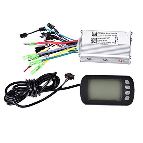
XLD500WController.jpg

The "power and electric lock" function is straightforward. The heavy red and black are your main battery power, and the orange wire is the "ignition" which provides battery power to the actual controller logic.

Phase and hall wires are standard, as well. There's a group of pads on the PCB - "5V", "U", "V", "W", and "GND" all together. These are the red, yellow, green, white, and black hall wires, respectively.

The EBS brake wires are both grey and, when jumpered together, turn on the braking (or regen, if true) capability - provided the LVC and power source are compatible. These are connected to pads labelled "DS" and "X" on the PCB

The "high potential brake" (it's purple) is an input signal that would be used if this controller were used on a scooter. You'd connect this to the same 12V signal that drives the bike's tail light. It goes to "SH" on the PCB and has the same effect as shorting the low potential brake.

The low "low potential" brake (the one most of us actually use) is a black and white, going to "GND" and "SL", respectively. When shorted, this switches off motor power and activates EBS.

The throttle ("handle accelerator", as diagrammed) is red, white, and black. Red goes to "+4.3V", black to "GND", and white to "SD" - the latter being the actual throttle signal.

The "gear switch" is the 3-speed control. Black goes to "GND", grey to "K1", and white to "K2". Left open, the motor runs at its "medium" speed. Short black to grey, and speed is reduced to "low". Short black to white and you get full speed.

The "reverse function" (brown and black, going "DC" and "GND", respectively) reverses the motor when shorted.

The "cruise function" (blue and black, going to "Q" and "GND", respectively) holds your current speed when shorted.

The "autometer signal" is interesting. It seems analogue (though probably just buffered PWM). The faster you go, the more voltage you read on this line. What's weird is that it hangs out of the controller, unprotected and uninsulated, but ramps up as high as 18V when the bike is at full throttle on a 39V pack. It's blue, and connected to "S+". I have no idea how I'd use this, though driving a regular analogue panel meter could be fun. :)

There are two connectors for an alarm function - which I have NO idea about.

Alarm power (red and black) goes to pads marked "PS+" and "GND".

Alarm signal is three wires - Grey goes to "A3", white goes to "W", and orange just brings back out full battery voltage (it's directly connected to the orange "ignition" wire).

Dunno if any of this is useful, but its the first time I've had my mitts on one of these "X806M" based controllers.

I'm dubious about the "sine wave" output of this thing. So far, the motor I'm playing with sounds exactly the same as it did with the older model Infineon job that was previously on there.

anyone know what is that "intelligent identification" wire pair?
edit: NVM, it's detection of hall sensor order... Didnt work for me though


also, what does these power and current mean on these? I have 1200W / 45A model. Can it run more than 1200W if current limited by CA to 45A at most.?
 
I Recently bought the XLD Brainpower motor controller XunLiDa - with control panel from https://www.ebay.de/str/binggoshop. The was no instruction in the package I recieved from them, and they are not replying to my messages.

I need to know how to “programme” the controller to make the bike run without hall sensor. As the bike/motor in the front wheel
originaly doesn't have a hall sensor.
I have read about other controllers, that run fine without hall sensors, however the bike doesn't run with the controller installed now.
I hope someone has experiences with the controller I got. I would be so happy to get an Instruction on how to programme the controller, in order for it to run without the hall sensor.

Picture 1: https://drive.google.com/file/d/1_TpIgLrWHt72BC24lyUhOAWuB2PAh-ND/view?usp=sharing
Picture 2: https://drive.google.com/file/d/1CxVUao6aEU51mRlA9VdHSg0c9h24hPC0/view?usp=sharing
Picture 3: https://drive.google.com/file/d/1JezLVYdpTQPOfsnPVR5hbtVULp54eUMG/view?usp=sharing
Picture 4: https://drive.google.com/file/d/1W4IEzkPlGhO7DRzSKIL0snY21k3fTEoI/view?usp=sharing
 
if yours is capable of sensorless operation, then these are the relevant posts in this thread:

https://endless-sphere.com/forums/search.php?keywords=sensorless&t=96736&sf=msgonly

if it's not, then it won't work with your motor, and you'd either need a different motor (sensored) or different controller (sensorless).
 
pederrudbeck said:
I Recently bought the XLD Brainpower motor controller XunLiDa - with control panel from https://www.ebay.de/str/binggoshop. The was no instruction in the package I recieved from them, and they are not replying to my messages.

I need to know how to “programme” the controller to make the bike run without hall sensor. As the bike/motor in the front wheel
originaly doesn't have a hall sensor.
I have read about other controllers, that run fine without hall sensors, however the bike doesn't run with the controller installed now.
I hope someone has experiences with the controller I got. I would be so happy to get an Instruction on how to programme the controller, in order for it to run without the hall sensor.

Picture 1: https://drive.google.com/file/d/1_TpIgLrWHt72BC24lyUhOAWuB2PAh-ND/view?usp=sharing
Picture 2: https://drive.google.com/file/d/1CxVUao6aEU51mRlA9VdHSg0c9h24hPC0/view?usp=sharing
Picture 3: https://drive.google.com/file/d/1JezLVYdpTQPOfsnPVR5hbtVULp54eUMG/view?usp=sharing
Picture 4: https://drive.google.com/file/d/1W4IEzkPlGhO7DRzSKIL0snY21k3fTEoI/view?usp=sharing

does it even feel like trying to run motor?

if yes, just ignore those hall wires, try this; https://i.imgur.com/HRaeRi4.jpg
HRaeRi4.jpg
 
file.php

For those interested, some more (deep dive) technical info about the above Infineon micro posted by philf earlier in this thread. This is likely a close variant of the Infineon XC886 processor, a quad package version of the dual sided XC836, both of which are still very popular in Chinese controllers (despite being called "legacy" by Infineon). A pinout of the XC886 is available: https://www.mouser.com/datasheet/2/196/Infineon-XC88XCLM-DS-v01_02-en-527737.pdf and programming reference manual: https://www.infineon.com/dgdl/XC800_Arch_UM_v0.2.zip?fileId=db3a304412b407950112b40c664f0b18
To answer a question posted earlier, it looks like the only security feature in these chips is write protect for flash, so the existing code should be able to be read using jtag (although personally haven't tried yet).
And apologies to anyone who already posted this info on endless-sphere, just couldn't find it!
 
I have a question I hope someone can answer. I have the 800w version of this controller. I have it connected to power and hall sensors and jumping the green wires gets it to spin. I'm wondering how the throttle connection works though. I figured it would be like the VFDs that we use at work where it sends out + and - and by sending + through a resistor and back to the third wire it would set speed. But when I do that or even short red to white I get nothing. I get 5v between the two with a multimeter. Any ideas? Thanks!
 
Throttle on just about any bldc ebike controller uses an analog output hall sensor.

Typically these have an output range from around 1v to around 4v.

To ensure a failure or short doesn't cause full-throttle operation, some controllers don't respond to any voltage above whatever is marked on them for the throttle voltage range.

You can use a potentiometer instead of a hall throttle, by putting the 5v from the ocntroller (usually red) on one of the outer legs of the pot, ground (usually black) on the ohter, and put the pot's wiper (center wire) to the throttle signal wire (usually green or white).

There are a lot of threads about throttle stuff if you need more information/etc. A few of them are in the lists below, though not everything in the lists is relevant, the titles should tell you which to start with. ;)

https://endless-sphere.com/forums/search.php?keywords=throttle*+hall*&terms=all&author=&sc=1&sf=titleonly&sr=topics&sk=t&sd=d&st=0&ch=300&t=0&submit=Search

https://endless-sphere.com/forums/search.php?keywords=throttle*+wir*&terms=all&author=&sc=1&sf=titleonly&sr=topics&sk=t&sd=d&st=0&ch=300&t=0&submit=Search
 
Hi everybody! I have a Xiaomi M365 scooter that I installed the brainpower 36-48V 13A with S866 kit to replace broken electronics and it just work fine with the 36V stock battery. I have a 2S battery lying around that I used with previous stock controller and I want to use it with that new controller.

Do I need to change anything in LCD (set voltage to 48V or something else)? Or just connect it?

Kind regards.
 
rocorbo said:
Hi everybody! I have a Xiaomi M365 scooter that I installed the brainpower 36-48V 13A with S866 kit to replace broken electronics and it just work fine with the 36V stock battery. I have a 2S battery lying around that I used with previous stock controller and I want to use it with that new controller.

Do I need to change anything in LCD (set voltage to 48V or something else)? Or just connect it?

My brainpower 13A controller could run on either 36 or 48, but its low voltage cutoff was hard wired for 30V. So I had to watch it if I had 48V on the bike, because the 30V LVC is too low for a 48V battery.

In your case, if your controller is smart enough to set LVC to 40V if it thinks it has a 13S 48V battery, that's a tiny bit too high for 12S. You'll lose some of the available range, If it happens to set the LVC to the 30V typical of a 10S pack, like me, you'll have to watch the voltage so it doesn't get lower than 36V.
 
Hi,

Thanks for the answer. As far I know, this board comes with a S866 LCD and it has a parameter to choose the cutoff: "P15: Controller undervoltage".

So if I choose a higher value than 30V, will it work fine? Kind regards for everything. In my case, I will be with 44.4V (12S) so I need to adjust it somewhere near 38V, I think. My setup will be a 10S battery + 2S in serial.

Kind regards.

Rodrigo
 
hola a todos, perdonar por meterme de por medio, tengo un problema.......como muchos de los aqui presentes jejejejejejej, tengo una controladora que pone asi; XLD BRAINPOWER ETC. 48V 1000W 38A BRAKE LOW, ITEM no. DG61. XuLiDa. En la salida pude encontrar dos cables para hacer girar el motor el accelerador no va y el sensor de los pedales tampoco lo encuentro indiferente de la configuracion que haga. Alguien aqui me puede ayudar a conectar el sensor de los pedales........o me puede decir como sacar 3 cables de una controladora para poner esos 3 cables? Por norma general diria yo, necesita 5v de salida ; uno rojo, uno negro, y uno blanco. Se pueden extraer de la placa donde pongan GND VCC algo asi? Gracias por su tiempo, un saludo
 
I ended up having somehing similar if not 1-1 with this brainpower controller, I actually have one with a display but its only 350W so I thought of rising the bar to 1.5kW but I still have 36V battery therefore I need to fool this controller to accept supply voltage as low as maybe 27V DC?

Not quite sure how this LTC works at this point. It seems the same? So just simply add resistance to 60V circuitry or is there anything else to do?
 

Attachments

  • Capture.JPG
    Capture.JPG
    82.8 KB · Views: 4,576
inglete said:
hola a todos, perdonar por meterme de por medio, tengo un problema.......como muchos de los aqui presentes jejejejejejej, tengo una controladora que pone asi; XLD BRAINPOWER ETC. 48V 1000W 38A BRAKE LOW, ITEM no. DG61. XuLiDa. En la salida pude encontrar dos cables para hacer girar el motor el accelerador no va y el sensor de los pedales tampoco lo encuentro indiferente de la configuracion que haga. Alguien aqui me puede ayudar a conectar el sensor de los pedales........o me puede decir como sacar 3 cables de una controladora para poner esos 3 cables? Por norma general diria yo, necesita 5v de salida ; uno rojo, uno negro, y uno blanco. Se pueden extraer de la placa donde pongan GND VCC algo asi? Gracias por su tiempo, un saludo

Translated to...
"Hi everyone, sorry for getting in the way, I have a problem ....... like many of us here hehehehehehehe, I have a controller that says so; XLD BRAINPOWER ETC. 48V 1000W 38A BRAKE LOW, ITEM no. DG61. XuLiDa. At the exit, I could find two cables to rotate the motor, the accelerator does not work and I do not find the pedal sensor indifferent either. Can someone here help me connect the pedal sensor ........ or can you tell me how to remove 3 cables from a controller to put those 3 cables? As a general rule I would say, you need 5v output; one red, one black, and one white. Can they be removed from the board where they put GND VCC something like that? Thanks for your time, greeting


Your thinking is correct. The wire wires of red, white, black may not be true,

You can get power and ground from any source on the board. You do have to know where the pedal sensor input would connect.
 
The resistor biggest SMDresistor on the picture 2402 (24kR) when paralelled with 10k resistor brings LTC down to 14V which is the absolute minimum. Coudnt get it any lower. Can be adjusted with higher calues but 10k vas the lowest I had in hand by the time...
I simply dont need LVP.
 
Hi, I'm struggling with a 24v XLD Brainpower bought to replace an old dead unmarked unit. Power input, motor hall, motor power, throttle hall and pedelec hall connected. With battery power to already looped ingnition line I have 5v red to black on throttle & pedelec. Battery link to throttle block gives 3 led indication OK. I have one line left from the throttle block that gives me 5v with the throttle switch 'on'.

As cabled the wheel doesn't turn with throttle or pedelec. If I link 'intelligent learning' lines together the wheel runs regardless of anything pressed or turned.

Do I have to connect the 'spare' switchable 5v from the throttle block somewhere to get the controller to listen to the pedelec or throttle. If so, where do I connect it.

Many thanks
 
Hebblet said:
I have 5v red to black on throttle & pedelec.
<snip>
As cabled the wheel doesn't turn with throttle or pedelec.
Red usually goes to red, and black usually goes to black. If for some reason black is the 5v lines of your throttle and PAS sensor, then the way you have it is right, but otherwise, you have them the wrong way, and it's possible to damage the electronics hooking them up backwards.

If I link 'intelligent learning' lines together the wheel runs regardless of anything pressed or turned.
That is correct. All that wire does is put the controller into a mode that "learns" the correct phase/hall wiring combo. Typically if you connect it, then disconnect it, and then connect it again, it reverses the motor direction (so you can have it learn the right way for your system). When it is working in the direction you need, disconnect and leave it that way.
 
Good evening, I recently installed a Brainpower XunLiDa XLD engine control unit on the Fiido D2. When I change the settings from the secret menu from the display, I switch off and on again but they are not saved. can anyone tell me the reason? thank you so much
 
philf said:
Rodrigoperez said:
Hey can you help me a Lil i have bought this controller for like a week now and i couldnt make it work any gess of what could It be ???
Like no power to the motor and what you need to do with like the Orange wirre and the alarm signal wire
I think the problem is there...
Thanks

The only wires you need (correctly) connected for the controller to actually turn the motor are the power, "ignition", hall sensors, phase wires, and throttle. The "ignition" wire needs to be connected to to the battery, the same as the main power line (many people just tie them together). This is the orange wire that's part of the three contact power connector, as the unit ships, and they refer to it as "electric lock" in the diagram I posted earlier in the thread. You can completely ignore the "alarm" wires - I have no idea what these do, and will remove them (along with some of the other wires I don't use) - just to clean things up.

Assuming everything is connected, it's possible that you have a mismatch between the controller's configured voltage and the battery you are using. If your battery is below the LVC (low voltage cut-off) that the controller is expecting, then you'll get nothing. If you've connected either of the brake lines, then disconnect those to make sure you aren't inadvertently triggering the cut-off associated with *them*.

Normally, there's a bit of an exercise to get the hall/phase wires sorted - with this controller, simply connecting the green auto-config ("intelligent identification", in the diagram) wires together should make the wheel spin (make sure the wheel is off the ground :)). If you're sure that power is wired correctly, and you've got enough voltage, then something is likely amiss with your hall/phase wiring.

Hope it's this simple!

Edit:

Just wanted to be clear about the "ignition"/"electric lock" (both misnomers, as far I'm concerned), in case it turns out to be this simple - you wouldn't want to to be running the battery randomly into any of the other orange or red wires on the controller. It's THESE wires that both need to be connected to the battery:


You *can* install a switch on the orange wire, which is what the intention was of bringing that wire out separately.
Hi! I had the same ignition pin confusion; after connecting the orange cable to battery +ve, the motor does turn on. But as soon as I accelerate, the motor makes weird kind of vibration sounds and the wheel does spin fully but I'm not sure about this vibration. The battery wires and the motor cable gets hot, the controller and motor itself are not heating up. Any reason for this vibration ( and weird sound- just like how a door creeks) and heating?

Sent from my SM-G960U1 using Tapatalk

 
dear friends, can somebody instruct a way to operate head lights on XLD LCD? lcd is 4 button type, older version. controller is brainpower a800. actually i have another controller with same company with higher power rating and its LCD is also same.

unit is similar to this:

51V89VkdCVL.jpg


on some web pages, it is işnstructed as pressing C button briefly would do the job done. question is which pair of wires can be used as switched light output?
 
Back
Top