if wha tyou have is two of these
https://www.ebay.com/itm/48v-1800w-Brushless-Motor-Speed-Controller-Foot-Pedal-Reverse-Switch-Chain-Sproc/303024861914?ssPageName=STRK%3AMEBIDX%3AIT&_trksid=p2057872.m2749.l2649
then the current limit on the controllers, meaning the continuous constant current maximum that they should draw, is 32a each, so 64a or so is the maximum continuous they should draw. they may spike higher at startup from a stop for a moment, but if their limits work like they should, they should settle down to 64a or so regardless of the load on the motors (even if it were such a load like a super steep hill or whatever, that makes the motors slow and stall).
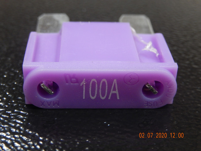
so it has a 100a fuse, meaning if the system draws more than 100a for long enough, the fuse would blow. that's unlikely except in the event of a failure, which is what the fuse is meant for.
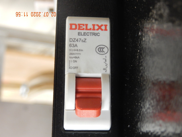
it also has "60a breakers" (plural?) doesn't state if those are in series or in parallel or how many there are. if they're in parallel, then you could draw over 120a before they overload and pop. if they're in series, then somewhere over 60a for long enough, and they'll pop.
it's not usually a hard-and-fast limit with breakers. i have an 80a (?) breaker on the sb cruiser trike, and it hasn't ever popped in normal use (just when testing short circuit protection; it does work for that). i've seen peaks in some tests well over 200a for a few seconds, and for a few seconds my normal startup current from a stop is 60-90a depending on cargo load, but my normal continuous current is in the high teens or low 20s, so well below the breaker limit.
yours should be, too, if everything is geared right, unless you're going up enough of a hill or riding against enough air resistance / wind to need full power from both motors.
but as always, it'll require actual testing of the system to find out what really happens.")
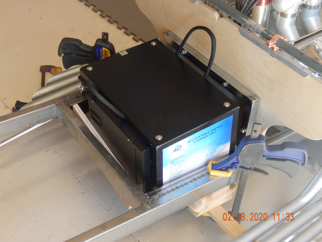
the battery specs here
https://www.techdirectclub.com/48-volt-nissan-leaf-lithium-ion-mini-power-pack-battery-3-5-kwh-66ah-g2/
are listed as
motor/controller specs from the first link
https://www.ebay.com/itm/48v-1800w-Brushless-Motor-Speed-Controller-Foot-Pedal-Reverse-Switch-Chain-Sproc/303024861914?ssPageName=STRK%3AMEBIDX%3AIT&_trksid=p2057872.m2749.l2649
then the current limit on the controllers, meaning the continuous constant current maximum that they should draw, is 32a each, so 64a or so is the maximum continuous they should draw. they may spike higher at startup from a stop for a moment, but if their limits work like they should, they should settle down to 64a or so regardless of the load on the motors (even if it were such a load like a super steep hill or whatever, that makes the motors slow and stall).
so it has a 100a fuse, meaning if the system draws more than 100a for long enough, the fuse would blow. that's unlikely except in the event of a failure, which is what the fuse is meant for.
it also has "60a breakers" (plural?) doesn't state if those are in series or in parallel or how many there are. if they're in parallel, then you could draw over 120a before they overload and pop. if they're in series, then somewhere over 60a for long enough, and they'll pop.
it's not usually a hard-and-fast limit with breakers. i have an 80a (?) breaker on the sb cruiser trike, and it hasn't ever popped in normal use (just when testing short circuit protection; it does work for that). i've seen peaks in some tests well over 200a for a few seconds, and for a few seconds my normal startup current from a stop is 60-90a depending on cargo load, but my normal continuous current is in the high teens or low 20s, so well below the breaker limit.
yours should be, too, if everything is geared right, unless you're going up enough of a hill or riding against enough air resistance / wind to need full power from both motors.
but as always, it'll require actual testing of the system to find out what really happens.
the battery specs here
https://www.techdirectclub.com/48-volt-nissan-leaf-lithium-ion-mini-power-pack-battery-3-5-kwh-66ah-g2/
are listed as
Nissan Leaf Generation 1 Battery
Weight: 70
Dimensions: 10 L x 14 in W x 10 in H
Chemistry: Lithium-ion
Battery Bank: 7 series
BMS integrated
DC Energy Capacity (100% Useable): 2.8 KWH
DC Nominal Voltage: 48 V
DC Voltage Range: 41 V – 58.8 V
Depending on inverter used.
1000 W – 5000 W inverter recommended.
Maximum Current Discharge: 60 A
Maximum Current Charge: 40 A
Storage Temperature: 0 – 89.6 F (-18 – 32 C)
Operating Temperature: 32 – 122 F (0 – 50 C)
Efficiency: >95% DC – DC depending on application.
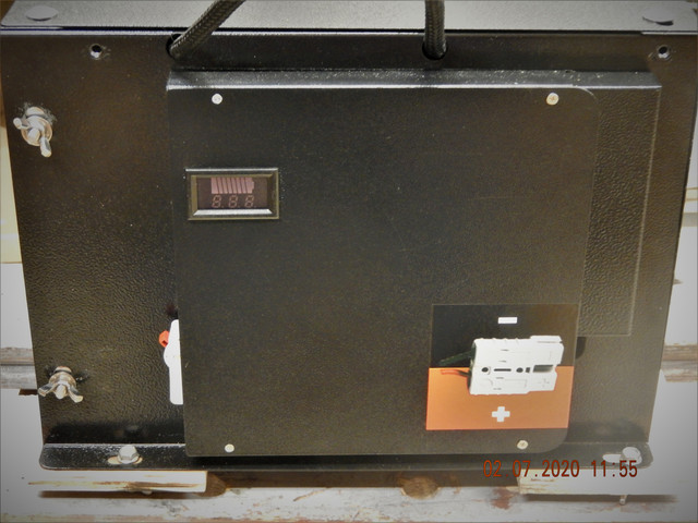
Fuse Protection: 100 A rated current per string.
Breakers: 60 amps
Design Life: 5+ years
LED DC Meter display the Voltage of each pack.
Nominal voltage 7.5V per module
Maximum charge Voltage 8.3V per module
End of discharge voltage 5.0V per module
Each cell voltage should be less than 4.15V per cell
Each cell voltage should be more that 2.5V per cell
25 ℃, SOC0-100% charging
25 ℃, SOC0-100% discharging
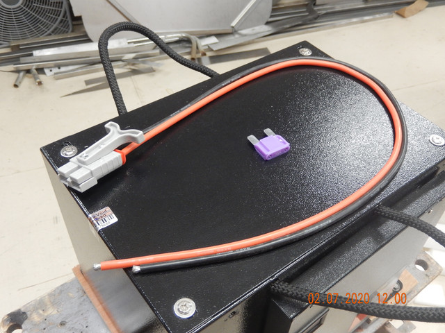
Connectivity: Anderson SB50
motor/controller specs from the first link
Motor Specification:
Style: striae & Round
Operating voltage: 5V
Adjustment range: Minimum ?1.0V; highest ?4.0V
Function: high, medium and low grades governor
Electric brushless Motor:
Type : Brushless DC Motor
Output Power: 1800W
Voltage : 48V
Speed: 4500rpm
Motor Sproket : T8F 9T
Brushless Controller:
rated voltage: dc 48 v
Current limit : 32A
rated power: 1800w
matching motor: dc brushless motorUnder Voltage Protection: 20V
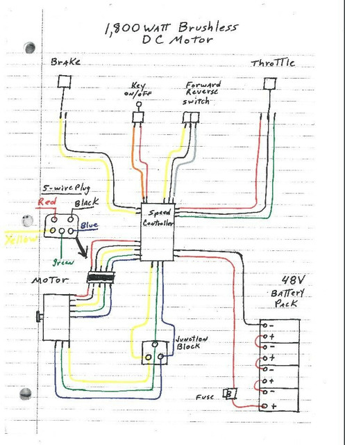
Wires Interface Definition
Battery :Thick Black (Power Negative) /Thick Red (Power Positive)
Motor :Thick Yellow (Motor Negative) /Thick Blue (Motor Positive)
Ignition Switch :Thin Red(VCC)/Thin Blue
Indicator : Thin red (Indicator power output) /thin black (indicator negative)
Brake :thin yellow (Brake signal)/thin black(Negative Power)
Speed governor :Thin blue(Speed handlebar Signal input) /Thin black (Negtive Power) /thin red(5V Positive Power)
Charge Port : Thin red (charge input power Positive) /thin black (Power negative)
Brake Light: Thin red (power Positive) /thin black (Power negative)
Package Including
1 x start motor
1 X controller box
1x Foot Pedal
1x Ignition Key Switch
1x Wire Harness
1x Forward Reverse Switch
1x T8F chain + rear sprocket