
You are using an out of date browser. It may not display this or other websites correctly.
You should upgrade or use an alternative browser.
You should upgrade or use an alternative browser.
Suzuki GSX-R e899 K2
- Thread starter Rovi
- Start date
j bjork
100 kW
It looks like a beast 
Is it totally custom made, or is it a model they have and wind to specification?
Is it totally custom made, or is it a model they have and wind to specification?
boars
100 W
That is nothing short of epic 
John in CR
100 TW
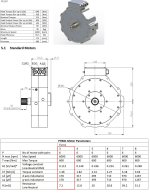
Wow! What are the dimensions of the stator on that beast of a motor (diameter and length)? Did they provide any motor specs like phase-to-phase resistance and no load current and rpm at a given voltage.
How will you mount the motor...extend the swingarm forward of the pivot so the motor doesn't act directly on the rear suspension?
You're going to have such a launch that I think you'll wish you made it even longer.
How will you mount the motor...extend the swingarm forward of the pivot so the motor doesn't act directly on the rear suspension?
You're going to have such a launch that I think you'll wish you made it even longer.
Hello John,
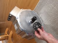
pls find attached some motor specs (3Turn version).
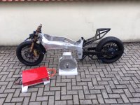
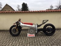
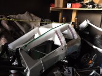
Well I want to install the motor as shown in the short video clip.
The batteries should be installed in two boxes which will be hanging under the frame extension so that the motor will be hide a little bit!
That means that the whole mass of motor, controller and batteries will be sprung.
To install it insde the swingarm is not possible because then the rear wheel will not fit anymore inside the swingarm and the wheel base will be to big to get the power on the track.
pls find attached some motor specs (3Turn version).
Well I want to install the motor as shown in the short video clip.
The batteries should be installed in two boxes which will be hanging under the frame extension so that the motor will be hide a little bit!
That means that the whole mass of motor, controller and batteries will be sprung.
To install it insde the swingarm is not possible because then the rear wheel will not fit anymore inside the swingarm and the wheel base will be to big to get the power on the track.
Attachments
John in CR
100 TW
With such a low Kv of 7rpm/volt giving it the capability of running 850V and peak input current of at least 450A for such short runs, what voltage are you planning for the battery? What kind of gearing ratio do you plan to try, since for a top speed highway run that motor should be able to handle even a 1:1 .
I just wish I could be there to help as part of your crew and see it run in person. It's going to be awesome with traction probably your biggest issue.
I just wish I could be there to help as part of your crew and see it run in person. It's going to be awesome with traction probably your biggest issue.
The controller max voltage is a little bit less than 800VDC.
So I will try to reach near to the max level but I will start first a lower voltage to some more experience.
Well the motor manufacturer told me that I can provide the full 600ARMS from controller to the motor.
The only thing I have to control is the max temperature of the windings which should not go higher than 145 degrees celsius.
Therefore they calculated a theoretically constant torque of 720Nm from 0-4K rpm. But that’s only theory!
I wanna use 1kW peltier Elements to cool down the motor and controller before a start. I am not sure it will work or not but if everything is going well I could cool down them to 10 degrees celsius.
And then we come to the transmission ratio!
I really don’t know the difference of Nm between a Hubmotor and the motor I have now!
My old hubmotor should have 400Nm at 600A peak current. I fed him with up to 899ARMS (1200A peak current). So QS motor calculated 550Nm max torque.
I made runs against 1000ccm motorcycles and they where much faster in accelleration than I!
Ok they have a gear box but nobody can tell me what kind of Nm they can provide at first gear!
I have heared stories about cars who can provide up to 3k Nm but ok they will be much heavier than my motorcycle! Or ducati which can provide up to 1200Nm in first gear ...
So my actually plan is to go first with a transmission of 19/45= 2,33 to see what happened @ 100A, 200A and so on. Maybe I will come to the point that 1:1 will be the best option later on as you recommend!
Well it would be nice to have you in my crew as a team member!
I will try to make as much videos as I can from the test runs I made to keep you and the others informed!
John in CR
100 TW
For the gear ratio, the way I'd go about it would be to work backward from the top speed I want to achieve. What speed do the gassers reach that you want to beat?
Great to follow your progress!
It would be easy to estimate the max usable torque if you know the weight, tire radius and distance between the center of mass and the rear wheel.
Top speed isn't everything, well as long as it's a timed run and not a speed run. An extreme acceleration could still beat someone with a higher top speed over the line.
Well, 270 kph will be a fantastic value!
So is there a percentage of no load vs load regarding speeds about 200kph?
I calculated 280kph at no load for my 163kg motorcycle with hubmotor and I reached 200,49 kph (GPS).
So I lost around 80kph inbetween.
At the end I will try to reach not more than 220kg. Actually the rolling chassie is about 73kg, the motor has 43kg and the controller 17kg= 133kg. Some material missing and the whole battery pack which I only calculated with 56kg. Means 189kg, so 31kg for the rest (Tank cover, open fairing, pumps, tubes, cabeling, mounting materieal ...
Actually I have 45 teeth for the rear sprocket and 19 teeth for the front (motor) sprocket.
The tyre radius is 31,6cm (12,44")
Well, the center off mass to rear wheel will be around 1m (40") but that value I have to guess.
Frank
100 W
I would suggest that you try to make the centerline of the motor as close to the OEM countershaft sprocket location as you can. The longer swingarm helps a lot of course. What is the wheelbase now?
Also, if there are any 1/8-mile (200 m) drag strips nearby, those might be a better venue for you. Still plenty fast and less energy consumed. True Cousins does most of their racing at an 1/8-mile strip (so do I).
Also, if there are any 1/8-mile (200 m) drag strips nearby, those might be a better venue for you. Still plenty fast and less energy consumed. True Cousins does most of their racing at an 1/8-mile strip (so do I).
Hi Frank,
Of course, I want to install the motor as close as possible to the OEM sprocket position but the radius of the motor will determine the position at the end.
Actually the wheel base is 16” over (mainframe 10” + 6” swingarm.
Well it’s hard to find 1/4 mile races here in GER.
I can use an airport landing field (1,1km lenght) for testing the motorcycle later on, as I did it in the past.
Additional I can use the dragy device to get some information about the times, speed and so on.
Frank
100 W
So wheelbase must be about 70"/175 cm? Do you have a link to the torque/power curve as a function of voltage?
Sent from my SM-T380 using Tapatalk
Sent from my SM-T380 using Tapatalk
Rovii said:Hi Frank,
Of course, I want to install the motor as close as possible to the OEM sprocket position but the radius of the motor will determine the position at the end.
If the chainline is above the swingarm pivot it will compress the rear suspension during acceleration (you would loose grip, seat goes down, bike tends to wheelie more i think).
So it cannot harm to have it below the pivot for drag racing, or do i miss something?
Awesome setup btw, is this a Yasa motor?
Rovii said:Well, 270 kph will be a fantastic value!
So is there a percentage of no load vs load regarding speeds about 200kph?
I calculated 280kph at no load for my 163kg motorcycle with hubmotor and I reached 200,49 kph (GPS).
So I lost around 80kph inbetween.
At the end I will try to reach not more than 220kg. Actually the rolling chassie is about 73kg, the motor has 43kg and the controller 17kg= 133kg. Some material missing and the whole battery pack which I only calculated with 56kg. Means 189kg, so 31kg for the rest (Tank cover, open fairing, pumps, tubes, cabeling, mounting materieal ...
Actually I have 45 teeth for the rear sprocket and 19 teeth for the front (motor) sprocket.
The tyre radius is 31,6cm (12,44")
Well, the center off mass to rear wheel will be around 1m (40") but that value I have to guess.
The achievable speed is not related to the no load speed at all, except it needs to be higher then the desired speed but how far into Field Weakening is of course also of relevance.
What decides the speed is the torque produced at the rear wheel and thus the force that is produced at the contact patch. The wheel torque is not only calculated by the motor torque and gearing but lower due to some losses in the transmission.
The achievable speed is the balance between the force produced by the motor on the contact patch and the rolling resistance of the wheels, bearings and also the aerodynamic drag.
Frank
100 W
^^ Correct. The generally accepted rule-of-thumb is that it takes about 200 hp to go 200 mph in a bike with reasonable aerodynamics. Your output of course will be a function of voltage which is why I was interested in those curves. I searched but couldn't find anything other than "typical" values which mean little if you don't know what the system voltage is.
I'm loving this project BTW! You're doing some things that I've only thought about before, keep up the great work!
I'm loving this project BTW! You're doing some things that I've only thought about before, keep up the great work!
Once you know the no-load current draw at low and high RPM, this can be refined for eddy and hysteresis torques, and of course it assumes no field-weakening (is your motor IPM?), but something for you to mess around a bit with for your bike. I assumed 196 cells charged to 4.1V @ 5Ah and guessed at a best case high-quality cell internal resistance. And, of course, real-world measurements can help you refine your Cd as well.
https://www.ebikes.ca/tools/simulat...me=road&mass=300&wheel=24i&blue=Nm&black=load
https://www.ebikes.ca/tools/simulat...me=road&mass=300&wheel=24i&blue=Nm&black=load
Thanks 
Well yes, my motor is IPM.
So at the end you think 5 Ah will be enough with high quality LiPos like the sleeper cell‘s from LV Lonestar?
I know there are existing 100/200C and 125/250C cells!
But to get it here to GER they will be very expensive!
I know, they are good quality I think.
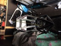
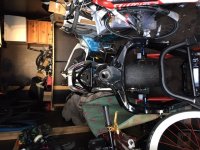
But first let me play with my old stuff/batteries. Actually my Intension is to get the motor with sprocket inside the frame.
Then the controller and after that the fuel tank cover dummy.
Btw I already experimented how it could be designed ...
I know not perfect but to get you a feeling how it looks like more or less later on ...
I wanna use the same tube dimension (1“) as for the rear tail. Closed on the top to lay down on it with carbon plates and open side’s.
Well yes, my motor is IPM.
So at the end you think 5 Ah will be enough with high quality LiPos like the sleeper cell‘s from LV Lonestar?
I know there are existing 100/200C and 125/250C cells!
But to get it here to GER they will be very expensive!
I know, they are good quality I think.
But first let me play with my old stuff/batteries. Actually my Intension is to get the motor with sprocket inside the frame.
Then the controller and after that the fuel tank cover dummy.
Btw I already experimented how it could be designed ...
I know not perfect but to get you a feeling how it looks like more or less later on ...
I wanna use the same tube dimension (1“) as for the rear tail. Closed on the top to lay down on it with carbon plates and open side’s.
Attachments
My best answer is I don't know. Arlo has mentioned some lightweight race cells in his CRX build thread. But if you have a set of batteries on hand that you can run the motor on, even if it's a much lower voltage than you want, you can get some good data from running as-is. 1.5 milliohms per cell may be optimistic for a 5Ah cell. Measuring a real cell after a handful of hard cycles to break it in would give you the best answer to that question. It will be a balance between weight, voltage drop, and battery wear/sturdiness.
Similar threads
- Replies
- 2
- Views
- 2,094