
Just_Ed
10 kW
I think I have figured out why they get 2.8kwh and we get 2.45kwh.
Maybe, it depends on where the calculator is made. :lol:
Maybe, it depends on where the calculator is made. :lol:
Just_Ed said:FWIW....This is the charger they sell with the battery pack.
http://www.cnczone.ru/forums/index.php?act=attach&type=post&id=10282


fechter said:With dual motors, when doing a tight turn, the inside wheel will have a higher loading and be doing most of the work. The current limit in the controller will keep it happy. It will act like an electronic differential with limited slip.
fechter said:There would be very little change in total power consumption between two motors vs. one motor if running at light load. Maybe around 5W.
Also....
Just to be sure, are your motors brushed or brushless? The controllers you showed are brushless and won't work with a brushed motor.
")
amberwolf said:but before you bother with any of this, try it out as-is first, as it will probably work just fine for you.
amberwolf said:fwiw, the eventual plan for the sb cruiser, assuming i stick with dual rear hubmotors, is to create an analog control operated by gearing or something on the steering that "divides" (not really but that's shorter and much simpler than a full explanation) the throttle signal between the two controllers whenever i'm turning, to give proportionally more power on the outboard wheel, and less on teh inboard, the sharper the turn is. but i haven't devised this yet.
Just_Ed said:Some more for the learning curve.
Also found a User Manual, for the charger/rectifier.
Got it through "Find Any Manual". Cost me a whopping .95 USD. Its coming from England, supposedly through email.
However, it hasn't arrived yet. They confirmed taking my money, and the status? ...well it's still processing.
They said it could take up to 24 hours before I get it. It's the first time I've ordered literature over the internet,
and I didn't get it nearly instantly. I spent a lot of 'cents', so it had better get here, post haste !
fechter said:Let me try my search-fu:
DELTA MCS-1800 series.pdf
This is some kind of rack mounted power bank unit that uses 4 of the smaller chargers. Some information applies.


Hillhater said:Hi Ed,..looking very impressive !
I know you are obviously a skilled :lol: and experienced engineer/ :lol: designer :lol: /fabricator :lol: , so dont take these comments as anything other than friendly thought from an idle pair of hands. :wink:
Just a couple of thoughts to keep your mind ticking over between “tool time”
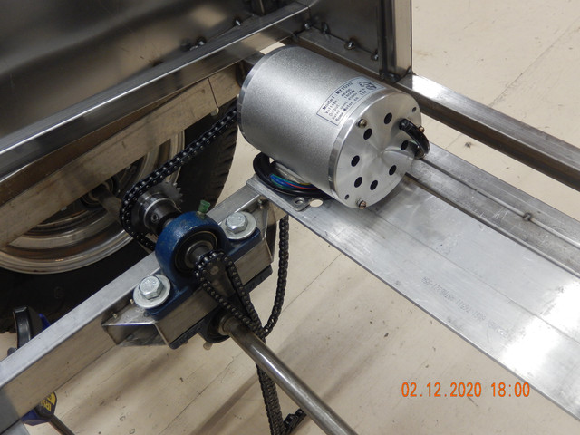
1) motor to axle drive train...i see no freewheels or sprags ? Hmmm, good point sir. The addtion of freewheels, will affect using reverse, I think.
With that reduction ratio, is it going to be hard work moving her manually without power. ? No, I'll have my wife pushing while I steer....JUST KIDDING
2). That 3/4 axle ??...once you split it, i just wonder how much axle/chassis flex may interfere with those chain lines ?..since you are rolling with no suspension.I just split the axle today. At less than 25 mph, and on relatively smooth-ish paved roads, I'm not really anticipating any problems. BUT road testing will surely tell us more.
The only similar situation i can think of is race go karts, where they moved from 1” axles , up through 30 mm, 40mm, and even 50 mm, hollow toughened, axles to avoid axle flex and chain problems. I guess I need to watch out for pot holes.
Anyway ,..in your situation, i guess you can afford to try it first, and change it later if there are any issues !
....more power to your welder !


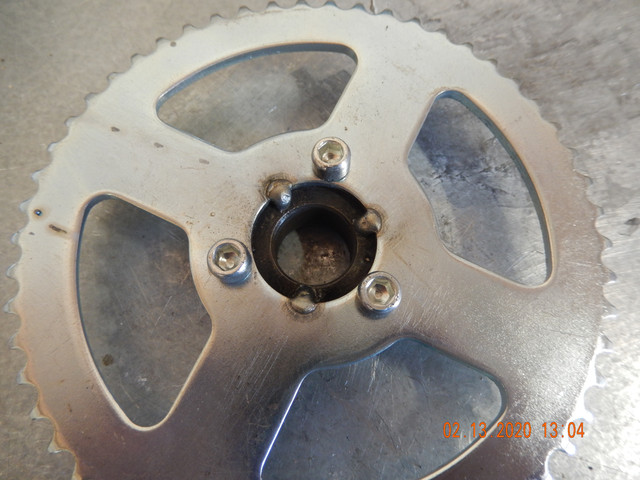

Hillhater said:[ That 3/4 axle ??...once you split it, i just wonder how much axle/chassis flex may interfere with those chain lines ?..since you are rolling with no suspension.
