Bafang brake cut-off 3 wires to 2 controller wires

Bryony

1 mW
Joined
Jan 7, 2020
Messages
18
Hi,

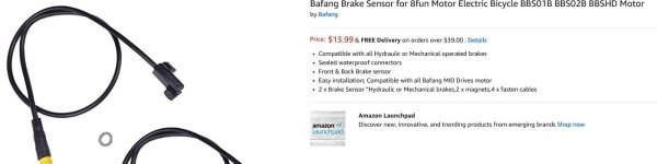
I need some help with fitting a Bafang Brake Sensor for 8fun Motor Electric Bicycle BBS01B BBS02B BBSHD Motor.

I guess the clue was in the name, but I thought I'd be able to use it on other kits, but maybe not. Is it even compatible with Voilamart and Yescom kits?

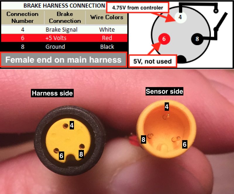
I cut it and it has 3 wires to the two on my controllers. Now I have read up on this for previous thread and can see advise to join up one of the wires with the 5v wire of the throttle, but I don't trust that I've got this completely right.

I did take pictures but they haven't uploaded. The bafang brake cut off has 3 wires, from memory red, blue and black. The controller has black and blue.

So do I join the black and blues and then the red with the red of the throttle? That's what I think I read on another thread?

Thanks

Bryony
 

Attachments

  • Bafang.JPG
    Bafang.JPG
    47.4 KB · Views: 5,770
Use you ohm meter to check pair combinations to find the two that are normally open when the brakes aren't actuated, and closed when the brake lever is actuated. Those would be the pair to use with most two wire brake connections with the controller.
 
More and more of the three wire ones are Hall sensor type, and won't work with cheap generic controllers looking for a two wire signal. The plus for manufacturers is they're harder to bypass...the whole system shuts down without the brake wires plugged in. The plus for users is nothing... It sucks in every other way except liability reduction.
 
Oh so nobody thinks this will work now, as previous threads suggested it would bit that's from a few years back?
 
It might depend on your system, it needs 5 volts in... And its looking for something near 5v out as the cutoff, but not less than a volt or so, as zero makes it think the brake is disconnected.
 
Bryony said:
Oh so nobody thinks this will work now, as previous threads suggested it would bit that's from a few years back?

If it's a hall based switch as Voltron describes, then it's not going to work. I assumed it was a reed switch, which often support NC and NO, and has three connections (and what you may end up needing).
 
It's been my impression that most of these add-on hydraulic brake kits are of the reed switch type.
Here is a pin-out of the brake connector as used on a Bafang mid drive as per the OP's description page. Perhaps it will help with vetting the wiring.


VFrWhip.jpg


The notations are for a reed type, and shows the general operation when used with LOW BRAKE controller wiring.

If after you follow E-HP's spot on instructions with the help of the map above...

"Use you ohm meter to check pair combinations to find the two that are normally open when the brakes aren't actuated, and closed when the brake lever is actuated. Those would be the pair to use with most two wire brake connections with the controller."

Just use the wires that open and close leaving the 5vdc input wire disconnected.

If the contacts don't open and close with the magnet's activation. You can still use it as a bipolar hall sensor brake actuator by connecting the 5vdc input wire to the controller's 5vdc regulated source. Accessed at the throttle, PAS, or motor hall sensor 5vdc input wiring. But making sure to connect the controller's brake signal (typically 3 to 5vdc positive) and the ground (negative) in the correct polarity to the brake's hall sensor's signal and ground. Unlike with the reed switch, correct polarity must be maintained!

In this configuration it would be wise to verify correct operation by keeping a volt meter on the 5vdc supply to the brake switch. Checking to see that when activated it doesn't change voltage. (shorted to ground) This would simulate a correct operation by losing 5vdc inputs... but certainly not desired for obvious reasons. With correct operation shorting or closing a connection between the brake signal and ground only.

FYI: This type of bipolar hall sensor operation is also seen in passive PAS sensors, external speed sensors, motor position hall sensors, and cable movement sensors (gear and brake). Where a digital on/off signal is used.
 
a hall type switch should work perfectly fine with a two wire type controller, if the controller is simply expecting the switch to ground the signal input when the lever is pulled. (all the generic ones i've worked with so far do this).

you just have to get 5v for the hall power from the throttle or wherever. then hook up the ground and signal wires to the corresponding wires on the controller.

when the hall is turned on, it will ground the signal line.


if the controller requires some other type of input, then using hall based sensors would be more complicated.
 
I just picked up a pair of these sensors off of eBay to interface to a CA V3. After cutting the plugs off and probing for the open/short circuit pin pair I noticed that the wire colors were different on the sensors I received. The reed switch is between pins 4 and 8 as labeled in the picture above, but the wires are black and red instead of white and black. Guess they don't care about the wire colors since the connector is overmolded.
 
Back
Top