KT motor controllers -- Flexible OpenSource firmware for BMSBattery S/Kunteng KT motor controllers (0.25kW up to 5kW)

Lesny said:
it is possible to change the configuration so that the controller uses the speed setting sent by uart like ori firmware ?

of course, if you progam it :D
But you can activate the offroad mode by the "morse code" with the break lever, so there is no need to change the max speed with the display...

regards
stancecoke
 
stancecoke said:
Lesny said:
it is possible to change the configuration so that the controller uses the speed setting sent by uart like ori firmware ?

of course, if you progam it :D
But you can activate the offroad mode by the "morse code" with the break lever, so there is no need to change the max speed with the display...

regards
stancecoke


I know but I would like to adapt the predefined driving modes and it would be easier to send the speed setting.
 
Lesny said:
it would be easier to send the speed setting.

If you want to have overall possibilities with your homebrewed arduino display, you should use the protocol of the BluOSEC app. With this you can change most parameters on the fly.
https://github.com/stancecoke/BMSBattery_S_controllers_firmware/blob/Master/BOdisplay.c

It uses the modbus protocol, for detailed questions you have to ask @Xnyle. The adresses of the parameters can be found in the BOdisplay.h

regards
stancecoke
 
I think it is too complicated for me because I program only in IDE and mainly deals with the electronic part.
The only thing I need is to change the maximum speed to do what I assumed.
Do you know where and what I would have to change the OpenSource code so that the controller does not ignore this value from Ktlcd3 uart?
 
you are lucky, Xnyle has implemted it already, I hadn't noticed that before. :)

Code:
void digestLcdValues(void) {

	ui8_assistlevel_global = lcd_configuration_variables.ui8_assist_level + 80; // always add max regen 
	// added by DerBastler Light On/Off
	light_stat = (light_stat&~128) | lcd_configuration_variables.ui8_light_On; // only update 7th bit, 1st bit is current status
	
	if (lcd_configuration_variables.ui8_max_speed != ui8_speedlimit_kph) {
		ui8_speedlimit_kph = lcd_configuration_variables.ui8_max_speed;
		eeprom_write(OFFSET_MAX_SPEED_DEFAULT, lcd_configuration_variables.ui8_max_speed);
	}
}

regards
stancecoke
 
stancecoke said:
you are lucky, Xnyle has implemted it already, I hadn't noticed that before. :)

Code:
void digestLcdValues(void) {

	ui8_assistlevel_global = lcd_configuration_variables.ui8_assist_level + 80; // always add max regen 
	// added by DerBastler Light On/Off
	light_stat = (light_stat&~128) | lcd_configuration_variables.ui8_light_On; // only update 7th bit, 1st bit is current status
	
	if (lcd_configuration_variables.ui8_max_speed != ui8_speedlimit_kph) {
		ui8_speedlimit_kph = lcd_configuration_variables.ui8_max_speed;
		eeprom_write(OFFSET_MAX_SPEED_DEFAULT, lcd_configuration_variables.ui8_max_speed);
	}
}

regards
stancecoke

So if I use the latest software and ktlcd3 protocol this should not be a problem with speed setting ?
 
Lesny said:
So if I use the latest software and ktlcd3 protocol this should not be a problem with speed setting ?
Yes, but I think it isn't prooved in hardware yet, as far as I know, Xnyle has no LCD3. So please report, if it works!

regards
stancecoke
 
Hi, i made own pcb using s06s KingQeen... scheme for my scooter, a check all seems like scheme, but it didn't work, no any reaction,
Vcap ok
OC 4.3v
An8 1.6v
I phase 2.5v
Using Chinese stlink v2
Looks like a microcontroller doesn't start/work
Help please
 
Slipy said:
Help please

sorry, but without the use of a scope, you won't find the error. First check the output of the bootstrap circuit (gate of the hi-side FETs)

regards
stancecoke
 
No any reaction, no any impulses on mosfet drivers, i think what microcontroller damaged if i can to ask you to do simple code for this stm, print on display uart hello word and enable all output ports as 1 (5v)
I will test it without HV part of pcb. I'm don't a programmer, only electronic, and make own home made scooter
Sorry for my English, I'm Ukrainian
 
If you use the stprog program, can you read the program memory from the microcontroller?
There also is a feature that the controller isn't starting up if one of the brake inputs is activated.
(It's starting up but not leaving it's initialising cycle.)
Be very carefull. If you activate both the upper and lower mosfet at the same time, they will short your power supply (or battery)
So it's best to at least disconnect the motor phase wires and use a current limited power supply or use a load in serie with your supply wires that limits the current. With the motor phase wires disconnected, the controller shouldn't use much current.
 
Hello

I am looking for a controller to use @48v with a torque sensor. It seems this one will fit the bill!

I can't realy find any info on how the torque sensor input signal can be calibrated from the documentation i find. Is it possible to calibrate it?

- Victor
 
Vbruun said:
Is it possible to calibrate it?

Yes, of course, but only linear. Throttle min is the offset and TQ calib the gain.
We don't use physical units for power/torque/cadence in the code to avoid unnecessary computations, but of course you can calculate them from the ADC and timer values, if you are really interested.

Slipy said:
print on display uart hello
Just flash the controller in diagnostics mode, then you should see communication on the UART pins.

regards
stancecoke
 
Thanks! I Guess the perfect way to do IT would be to also factor in the cadence in some way and calculate power, but I think this way Will be sufficient for what I am doing :)
 
Vbruun said:
I Guess the perfect way to do IT would be to also factor in the cadence in some way and calculate power
The assistance is proportional to the riders power, not to the torque on the pedal:

Code:
else { // torque sensor mode

	float_temp = (float) ui16_sum_torque;
	float_temp *= ((float) ui8_assist_percent_actual / 100.0);

	if (flt_torquesensorCalibration != 0.0) {
		float_temp *= flt_torquesensorCalibration / ((float) ui16_time_ticks_between_pas_interrupt_smoothed); 				
	}
}

regards
stancecoke
 
I'm sorry this is a bit OT, but this seem to be the place to ask about KT hardware and software :wink:

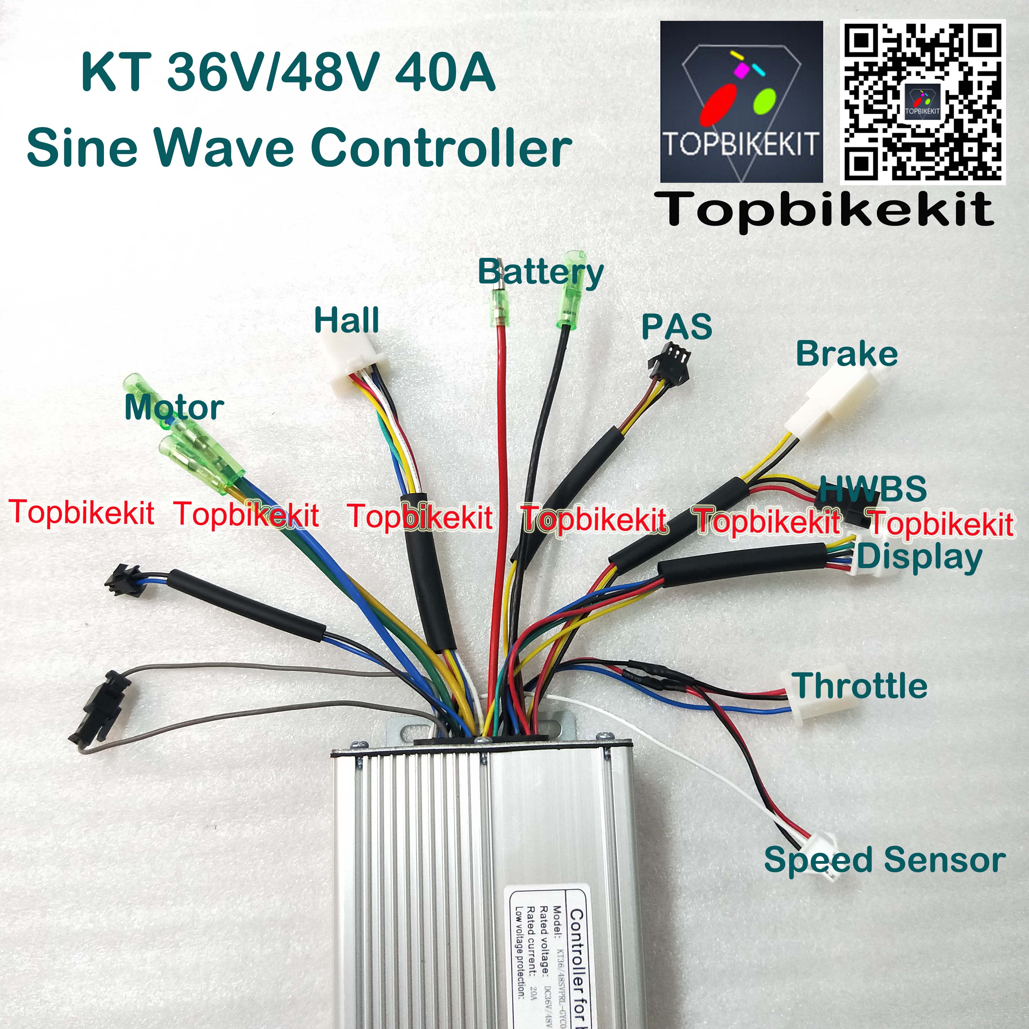
Does anyone know what the 3 unmarked connectors on the left could be for (2 of them are connected in the picture)?
T12H-36V-48V1000W-40A-12-Mosfet-KT-Torque-Simulation-Sine-Wave-controller-for-ebike-motor-ebike.jpg
 
Some controllers have a 36V output for a headlight / backlight.
It's usually a small additional pcb in the controller that has the switching fet for that output.
Some controllers have an auto sensing of the hall sensor wires.
In such case you usually have to disconnect a link for the auto detect (learning) mode to become active.
It's also possible that the link is there to disable / enable the street legal speed limit.
 
Hi, I started the controller but there was a problem, the motor does not stop, and it spins very slowly, when you press the brake, spin further, but does not respond to the throttle
 
Disconnect the throttle plug and see if it behaves identical with the throttle disconnected.
Measure the voltage between the blue and black throttle wire with and without full throttle.
Check if there isn't a walk assist that somehow got enabled.
 
Slipy said:
Hi, i made own pcb using s06s KingQeen.

Slipy said:
Hi, I started the controller but there was a problem, the motor does not stop, and it spins very slowly, when you press the brake, spin further, but does not respond to the throttle

Are you still talking about your homebrewed controller?
Hm, a remote diagnosis is always difficult. Can you discribe your setup. Which components are connected, are you sure, that the componets are working in principle, which settings and which SDCC version are you using? ....

I recommend to flash the controller to diagnostics or OSEC mode and look at the raw values of the peripherals and the controller state variable.

regards
stancecoke
 
Which setting of timer for ir2101
Original :
TIM1_OCPOLARITY_HIGH,
TIM1_OCNPOLARITY_LOW,
TIM1_OCIDLESTATE_RESET,
TIM1_OCNIDLESTATE_SET)
I change
TIM1_OCPOLARITY_HIGH,
TIM1_OCNPOLARITY_HIGH,
TIM1_OCIDLESTATE_RESET,
TIM1_OCNIDLESTATE_RESET)

But I'm not sure about the TIM1_OCNIDLESTATE_RESET or SET
Should a motor without a throttle stick brake all the time? I apologize for the anxiety, I really want to do it, since it is very expensive to buy
THANK YOU!!
 
Hi, I want to ask for a little help I have a controller, KT-lcd 8 display and 48v 1500w motor, the phenomenon that soon enough to disable the controller, I think the battery is weak I attach pictures, 48v 12ah battery
Thank you!
KT36/48 SVPRK-SLSO2G
battery :Ncr 18650B Panasonic 13s3p 48v /12ah
I would still be wondering how much voltage the controller 84 could withstand, it would definitely go much faster. Too bad there is no 3 speed function in it that could increase the speed by default. Can I really get a lot more out of the controller if I put the new software on it? Although it works very well with the kt lcd 8 display. Could the BMS function be turned off? I don't think it's a good idea to go as long as there are amps in the battery, don't turn it off ☺️😁🤪😃😛
 
cnrd said:
I'm sorry this is a bit OT, but this seem to be the place to ask about KT hardware and software :wink:

Does anyone know what the 3 unmarked connectors on the left could be for (2 of them are connected in the picture)?
T12H-36V-48V1000W-40A-12-Mosfet-KT-Torque-Simulation-Sine-Wave-controller-for-ebike-motor-ebike.jpg

Hi what is plugged in is the cruise feature, I pulled it apart I don't use it. The other is lamp lighting
 
Back
Top