KT motor controllers -- Flexible OpenSource firmware for BMSBattery S/Kunteng KT motor controllers (0.25kW up to 5kW)

Hello I'm new to the community here, I looked into Casainho and Stance work on the opensource firmware for KT controllers here
https://github.com/stancecoke/BMSBatter ... s_firmware
I do have KT controller/like which uses STM8S207 44 pin QFP. The entire firmware is built for STM105C 48 pins QFP, wondering what are the changes in the repo I may have to do to burn the EEPROM?
Any help is highly appreciated

Sorry this may be already answered somewhere

Thanks,
thunderbolt
 
SlowCo said:
sascha121985 said:
- I have a rear hub motor with 1000W.

Then why are you using a 500W controller? And are you using regenerative braking with that 1kW hub?
Just get a 1500W controller if your battery and BMS can handle it.

I know that the controller is to small for my motor. but i got this motor for free and don't need the full power.
That is the reason of the small controller.

Do you mean that the regenerative braking is the reason of the high temperatur.
But i'm also use that feature with the stock controller.

best regards
Sascha
 
sascha121985 said:
But it gets so hot, that is swith off automaticly.

There is no "automatic switch off" in the controller. What ist getting hot? The big resistor or the FETs with the complete housing?

Have you adjusted the motor specific angle properly?

regards
stancecoke
 
stancecoke said:
sascha121985 said:
But it gets so hot, that is swith off automaticly.

There is no "automatic switch off" in the controller. What ist getting hot? The big resistor or the FETs with the complete housing?

Have you adjusted the motor specific angle properly?

regards
stancecoke

It goes out. And after 5 minutes i can restart it again.
Not sure why, but it happend like this.

I must test what get hot. At the last ride the housing was closed, so i had no possibility to chek where the heat came from.

About the motor specific angle. I changed it several times over the bluethoothapp and checked when the engine starts best.
Or is there another way to determine that?

best regards
Sascha
 
sascha121985 said:
It goes out. And after 5 minutes i can restart it again.

This seems to be a problem with the 5V supply. Make sure, that you don't have other devices on the 5V supply than PAS, Brake and Throttle. For additional devices use a separate step down converter.

sascha121985 said:
Or is there another way to determine that?
find the angle with the lowest current draw at idle run.

regards
stancecoke
 
stancecoke said:
sascha121985 said:
It goes out. And after 5 minutes i can restart it again.

This seems to be a problem with the 5V supply. Make sure, that you don't have other devices on the 5V supply than PAS, Brake and Throttle. For additional devices use a separate step down converter.

sascha121985 said:
Or is there another way to determine that?
find the angle with the lowest current draw at idle run.

regards
stancecoke

Good morning,

i have test it yesterday with opened controller.
After a short ride of 1km the big restistor gets warm. Round about 50°C The Mosfets were cool.Round about 28°C.
So I think the problem at a longer rides came from the resistor.
What is it for?

I have only pas, throttle, brake and the KT LCD3 direkt at the controller.
But i have the same conncetions at the stock one. The bt device has a separate stepdown.
But i would like to use the display normlay. bt only for debugging.

Should i install a stepdown also for the display? But the display does not use 5V or i'm wrong?

Best regards
Sascha

EDIT: OK the resitor is to drop the voltage down. But what schoul i do know? I check later the value of it. I use a 48V Batterie.
Do the white blue and grey cables play any role at all? ( speed limit, regen ,...)

EDIT 2: The colors are red grey or black and brown. (200 - 280 ohm) When i measured it inside the control a can see 210ohm.
I have the same resistors in both Controllers (stock and custom)
 
i have test it yesterday with opened controller.
After a short ride of 1km the big restistor gets warm. Round about 50°C The Mosfets were cool.Round about 28°C.
So I think the problem at a longer rides came from the resistor.
What is it for?

The subject of the series resistor and the associated LM317 has been much discussed on this thread previously.
Suggest you do a search on this thread for 'LM317', you'll find lots of info that should help you... :wink:
 
geofft said:
i have test it yesterday with opened controller.
After a short ride of 1km the big restistor gets warm. Round about 50°C The Mosfets were cool.Round about 28°C.
So I think the problem at a longer rides came from the resistor.
What is it for?

The subject of the series resistor and the associated LM317 has been much discussed on this thread previously.
Suggest you do a search on this thread for 'LM317', you'll find lots of info that should help you... :wink:

OK thanks a lot.
I have read the relevant threads and found out that the best was is to change the LM317 and the resistore with a V7815W.
But it is not so easy to order in germany.
What can i also use? Every dc dc converter with an Output of 15V?
 
Sorry not reading this whole thread.

Is there a good wiki summary of the important stuff?

What is the biggest phase-amp hardware to which this software applies?

Is true FOC available? variable regen? field weakening?
 
Hi all in forum!
Big respect and thank you for sharing this valuable work with open source fw!!
I had use this opportunity during winter time and update my bike from 36v square to 48v simplified FOC and now after first test drive… just to say wow everything seems to work near perfect.
So quiet and smooth operation and nice jump for max speed 8)

Shortly about background:
After riding season in Finland late autumn 19.. when I maintenance/inspect my hub motor I found there was already machined groves to hall sensors.. I've started to research how to go for sine wave control, I found these cheap Kunteng sine type controllers might suit for my needs, and if there is a some reason i can go even open source, witch isn’t my main target at beginning!

When i installing hall sensors I found that they was in 60deg orientation instead of 120deg and after playing with original-fw settings I found that stock couldn't wont work properly and quite quickly I jump to for OSEC.

Here is little summary what changes i had to make to get all this to work at this point. [Branch Master]

60deg commutation I’ve adapted by invert c-phase signal -> changing following line in motor.c

Code:
        //hall_sensors = (GPIO_ReadInputData(HALL_SENSORS__PORT) & (HALL_SENSORS_MASK));
	hall_sensors = ((GPIO_ReadInputData(HALL_SENSORS__PORT) & (HALL_SENSORS_MASK)) ^4);

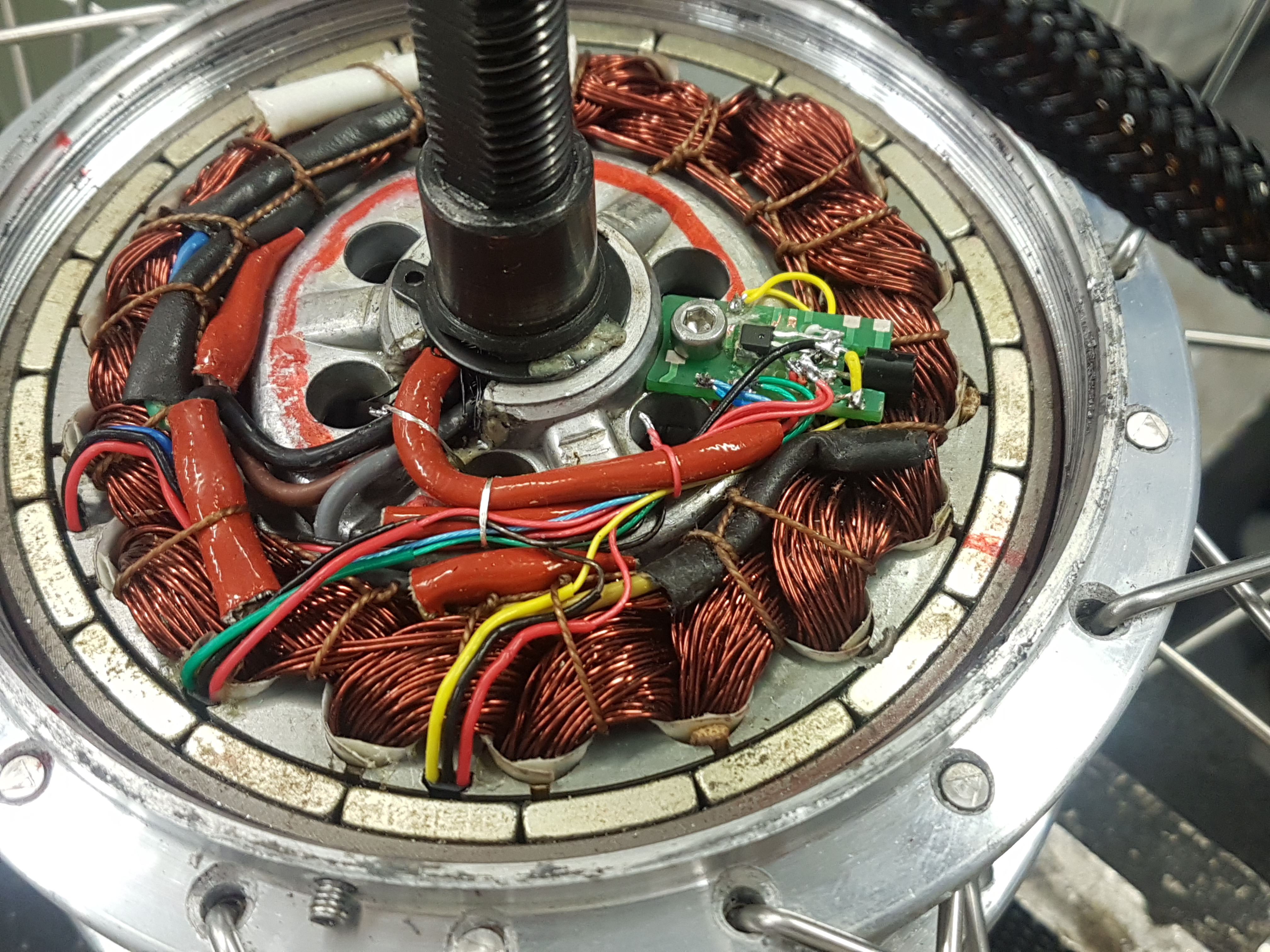
Same time when motor was open I added a separate hall sensor and magnet for embedded "in hub" speed signal and also a LM35 temperature sensor for winding.
motor.jpg


Following changes and additions i have made to get LCD6 (stock fw) to work with these changes.

ACAcommons.c
Code:
void updateX4(void) {
ui16_x4_value = ui16_adc_read_x4_value(); 
	//TEPA76 ADD
	//LM35 has scale 0-150C/0-1500mV
	ui8_motor_temperature =  (ui16_x4_value * 500) >> 10;  //LM35 degrees  C ... type changed to uint propably don't needed..
}

display.c file with comments
Code:
/*
Generic display init and update functions
Written by jenkie and Thomas Jarosch
Functions for the Nokia graphical screen mainly by m--k
King-Meter library and support written by Michael Fabry

This program is free software; you can redistribute it and/or modify
it under the terms of the GNU General Public License as published by
the Free Software Foundation; either version 3 of the License, or
(at your option) any later version.

This program is distributed in the hope that it will be useful,
but WITHOUT ANY WARRANTY; without even the implied warranty of
MERCHANTABILITY or FITNESS FOR A PARTICULAR PURPOSE.  See the
GNU General Public License for more details.

You should have received a copy of the GNU General Public License
along with this program; if not, write to the Free Software Foundation,
Inc., 51 Franklin Street, Fifth Floor, Boston, MA 02110-1301  USA
 */

#include <stdio.h>
#include "stm8s.h"
#include "display.h"
#include "main.h"
#include "config.h"
#include "stm8s_itc.h"
#include "uart.h"
#include "adc.h"
#include "brake.h"
#include "ACAeeprom.h"
#include "interrupts.h"
#include "ACAcontrollerState.h"

#ifdef DISPLAY_TYPE_KT_LCD3

display_view_type display_view;
display_mode_type display_mode; //currently display mode
float current_display;
uint8_t battery_percent_fromcapacity = 11; //hier nur als Konstante um Batterie normal zu senden....


uint8_t ui8_tx_buffer[12];
uint8_t ui8_j;
uint8_t ui8_crc;
uint16_t ui16_wheel_period_ms = 4500;
uint16_t ui16_battery_bars_calc = 0;
uint8_t ui8_battery_soc = 12;
uint8_t ui16_error;
uint8_t ui8_rx_buffer[13];
uint8_t ui8_rx_buffer_counter = 0;
uint8_t ui8_byte_received;
uint8_t ui8_moving_indication = 0;
uint8_t ui8_UARTCounter = 0;
uint8_t ui8_controlByte10 = 0;		//TEPA76 added Byte10 ...cadence
uint8_t ui8_PAS_period_ms = 0;		//TEPA76 added Byte11 ...cadence

volatile struc_lcd_configuration_variables lcd_configuration_variables;

void display_init(){
	// noop just here to have a common interface
}

//#define DIAGNOSTICS || #define DISPLAY_TYPE_KT_LCD3 || #define BLUOSEC
void send_message() {

	// prepare moving indication info
	ui8_moving_indication = 0;
	if (brake_is_set()) {ui8_moving_indication |= (1 << 5);}			//brake is on

	//if (throttle_is_set ()) { ui8_moving_indication |= (1 << 1); }
	if(ui16_momentary_throttle > 1){ui8_moving_indication |= (1 << 1);} 		//TEPA76 added Set bit1 when momentary Throttle has values
	else if (ui8_adc_read_throttle() > 5){ui8_moving_indication |= (1 << 0);}	//TEPA76 added Set bit0 when Throttle sensor is connected but leave clear if momentary have value

	//if (ebike_app_cruise_control_is_set ()) { ui8_moving_indication |= (1 << 3); }


	//TEPA76 added Cadence display in LCD6
	ui8_controlByte10 |= (1 << 7);		//set bit7 Byte10 by default... unknown function
	if (PAS_is_active) {
	    ui8_moving_indication |= (1 << 4);	//bit4 for enable cadence calculation and pedaling symbol in LCD6
	    ui8_controlByte10 &= ~(1 << 7);	//clear bit7 Byte10 when pedaling... unknown function
	}


        //TEPA76 added for cadence function in LCD6
	ui8_PAS_period_ms =  ((uint32_t) ui16_time_ticks_between_pas_interrupt << 6) / 1000;	//LCD6 protocol takes periods in ms. Send raw value since LCD6 buffering for avg value


	if (((ui16_aca_flags & EXTERNAL_SPEED_SENSOR) == EXTERNAL_SPEED_SENSOR)) {
		if (ui16_time_ticks_between_speed_interrupt > 65000) {
			ui16_wheel_period_ms = 4500;
		} else {
			ui16_wheel_period_ms = (uint16_t) ((float) ui16_time_ticks_between_speed_interrupt / ((float) ui16_pwm_cycles_second / 1000.0)); //must be /1000 devided in /125/8 for better resolution
		}
	}else{
		if (ui32_erps_filtered == 0) {
			ui16_wheel_period_ms = 4500;
		} else {
			ui16_wheel_period_ms = (uint16_t) (1000.0 * (float) ui8_gear_ratio / (float) ui32_erps_filtered);
		}
	}

	// calc battery pack state of charge (SOC)
	ui16_battery_bars_calc = ui8_adc_read_battery_voltage() - ui8_s_battery_voltage_min;
	ui16_battery_bars_calc<<=8;
	ui16_battery_bars_calc /=(ui8_s_battery_voltage_max-ui8_s_battery_voltage_min);
	
	if (ui16_battery_bars_calc > 200) {
		ui8_battery_soc = 16;
	}// 4 bars | full
	else if (ui16_battery_bars_calc > 150) {
		ui8_battery_soc = 12;
	}// 3 bars
	else if (ui16_battery_bars_calc > 100) {
		ui8_battery_soc = 8;
	}// 2 bars
	else if (ui16_battery_bars_calc > 50) {
		ui8_battery_soc = 4;
	}// 1 bar
	else {
		ui8_battery_soc = 3;
	} // empty

	ui8_tx_buffer [0] = 65;
	// B1: battery level
	ui8_tx_buffer [1] = ui8_battery_soc;
	// B2: 24V controller
	ui8_tx_buffer [2] = ui8_battery_voltage_nominal;
	// B3: speed, wheel rotation period, ms; period(ms)=B3*256+B4;
	ui8_tx_buffer [3] = (ui16_wheel_period_ms >> 8) & 0xff;
	ui8_tx_buffer [4] = ui16_wheel_period_ms & 0xff;

	//Send confirming signal for activating offroad mode
	if (ui8_offroad_state == 4) { //quitting signal for offroad mode enabled. Shows about 80 km/h for three seconds

		ui8_tx_buffer [3] = (100 >> 8) & 0xff; //100ms are about 80 km/h @ 28" 2200mm wheel circumference
		ui8_tx_buffer [4] = 100 & 0xff;
	}

	// B5: error info display
	ui8_tx_buffer [5] = ui16_error;

	// B6: CRC: xor B1,B2,B3,B4,B5,B7,B8,B9,B10,B11
	// 0 value so no effect on xor operation for now
	ui8_tx_buffer [6] = 0;

	// B7: moving mode indication, bit
	// bit throttle 	:0	-> clear when throttle
	// bit throttle 	:1	-> set when throttle
	// bit pas		:4	-> set when pedaling
	// PAS_is_active
	ui8_tx_buffer [7] = ui8_moving_indication;


	// B8: 4x controller current
	// Vbat = 30V:
	// - B8 = 255, LCD shows 1912 watts
	// - B8 = 250, LCD shows 1875 watts
	// - B8 = 100, LCD shows 750 watts
	// each unit of B8 = 0.25A
        ui8_tx_buffer [8] = (uint8_t) ((((ui16_BatteryCurrent - ui16_current_cal_b + 1) << 2)*10) / ui8_current_cal_a);

	// B9: motor temperature
	//if temperature >= 120 C sign in LCD screen is flashing. e.g 0xDA T=-23C, 0x34 T=67C
	ui8_tx_buffer [9] = ui8_motor_temperature - 15; //according to documentation at endless sphere


        // B10 and B11: Cadence
	ui8_tx_buffer [10] = ui8_controlByte10;			//bit4 enable for cadence calculation and pedaling symbol in LCD6, bit7 is invert of bit4
	ui8_tx_buffer [11] = ui8_PAS_period_ms;			//PAS pulse period ms


	// calculate CRC xor
	ui8_crc = 0;
	for (ui8_j = 1; ui8_j <= 11; ui8_j++) {
		ui8_crc ^= ui8_tx_buffer[ui8_j];
	}

	ui8_tx_buffer [6] = ui8_crc;

	// send the package over UART
	for (ui8_j = 0; ui8_j <= 11; ui8_j++) {
		uart_put_buffered(ui8_tx_buffer [ui8_j]);
	}
}

/********************************************************************************************/
// Process received package from the LCD
//

void digestLcdValues(void) {

	ui8_assistlevel_global = lcd_configuration_variables.ui8_assist_level + 80; // always add max regen 

	// added by DerBastler Light On/Off
	light_stat = (light_stat&~128) | lcd_configuration_variables.ui8_light_On; // only update 7th bit, 1st bit is current status
	
	walk_stat = lcd_configuration_variables.ui8_WalkModus_On;	//TEPA76 added

	if (lcd_configuration_variables.ui8_max_speed != ui8_speedlimit_kph) {
		ui8_speedlimit_kph = lcd_configuration_variables.ui8_max_speed;
		eeprom_write(OFFSET_MAX_SPEED_DEFAULT, lcd_configuration_variables.ui8_max_speed);
	}
}

// see if we have a received package to be processed
//uint8_t ui8_count = 0;
void display_update() {

	// fill local buffer from uart ringbuffer
	uart_fill_rx_packet_buffer(ui8_rx_buffer, 13, &ui8_UARTCounter);
	
	// Check for reception of complete message
	if ((ui8_UARTCounter > 12) || (ui8_rx_buffer[ui8_UARTCounter - 1] == 0x0E)) {
		ui8_UARTCounter = 0;

		// validation of the package data
		ui8_crc = 0;
		for (ui8_j = 0; ui8_j <= 12; ui8_j++) {
			
			if (ui8_j == 5) continue; // don't xor B5 
			ui8_crc ^= ui8_rx_buffer[ui8_j];
		}

		// see if CRC is ok
		if (((ui8_crc ^ 10) == ui8_rx_buffer [5]) || // some versions of CRC LCD5 (??)
				((ui8_crc ^ 1) == ui8_rx_buffer [5]) || // CRC LCD3 (tested with KT36/48SVPR, from PSWpower)
				((ui8_crc ^ 2) == ui8_rx_buffer [5]) || // CRC LCD5
				((ui8_crc ^ 3) == ui8_rx_buffer [5]) || // CRC LCD5 Added display 5 Romanta
				((ui8_crc ^ 4) == ui8_rx_buffer [5]) ||
		    		((ui8_crc ^ 5) == ui8_rx_buffer [5]) ||
		    		((ui8_crc ^ 6) == ui8_rx_buffer [5]) ||
		    		((ui8_crc ^ 7) == ui8_rx_buffer [5]) ||
		    		((ui8_crc ^ 8) == ui8_rx_buffer [5]) ||
				((ui8_crc ^ 9) == ui8_rx_buffer [5])) // CRC LCD3
		{
			// added by DerBastler Light On/Off 
			lcd_configuration_variables.ui8_light_On = ui8_rx_buffer [1] & 128;
			// added by DerBastler Walk On/Off 
			//lcd_configuration_variables.ui8_WalkModus_On = ui8_rx_buffer [1] & 64;
			lcd_configuration_variables.ui8_WalkModus_On = (ui8_rx_buffer [1] & 6)==6;	//TEPA76 modded for LCD6

			lcd_configuration_variables.ui8_assist_level = ui8_rx_buffer [1] & 7;
			lcd_configuration_variables.ui8_max_speed = 10 + ((ui8_rx_buffer [2] & 248) >> 3) | (ui8_rx_buffer [4] & 32);
			lcd_configuration_variables.ui8_wheel_size = ((ui8_rx_buffer [4] & 192) >> 6) | ((ui8_rx_buffer [2] & 7) << 2);

			lcd_configuration_variables.ui8_p1 = ui8_rx_buffer[3];
			lcd_configuration_variables.ui8_p2 = ui8_rx_buffer[4] & 0x07;
			lcd_configuration_variables.ui8_p3 = ui8_rx_buffer[4] & 0x08;
			lcd_configuration_variables.ui8_p4 = ui8_rx_buffer[4] & 0x10;
			lcd_configuration_variables.ui8_p5 = ui8_rx_buffer[0];

			lcd_configuration_variables.ui8_c1 = (ui8_rx_buffer[6] & 0x38) >> 3;
			lcd_configuration_variables.ui8_c2 = (ui8_rx_buffer[6] & 0x37);
			lcd_configuration_variables.ui8_c4 = (ui8_rx_buffer[8] & 0xE0) >> 5;
			lcd_configuration_variables.ui8_c5 = (ui8_rx_buffer[7] & 0x0F);
			lcd_configuration_variables.ui8_c12 = (ui8_rx_buffer[9] & 0x0F);
			lcd_configuration_variables.ui8_c13 = (ui8_rx_buffer[10] & 0x1C) >> 2;
			lcd_configuration_variables.ui8_c14 = (ui8_rx_buffer[7] & 0x60) >> 5;

			digestLcdValues();
			send_message();
			/*
			if(ui8_count > 19){
			  send_message();
			  ui8_count =0;
			}
			ui8_count ++;
			*/
		}
	}
}

#endif

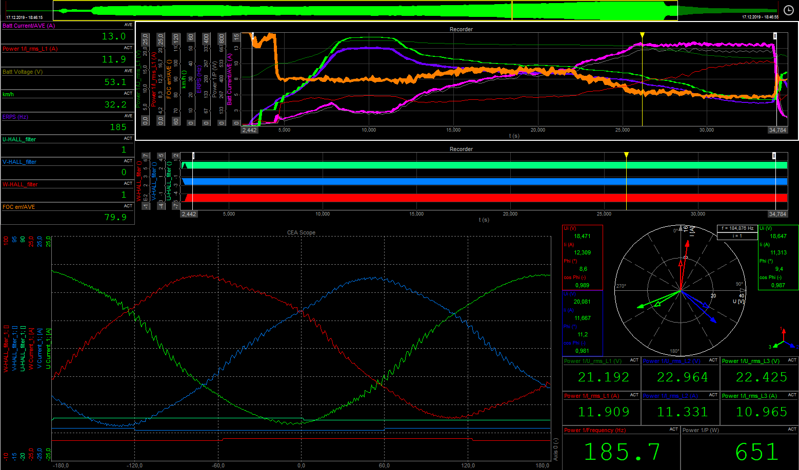
Here's a some early stage shot when battery current was limited to 13A.. first with throttle to accelerate at full speed (without load) then gradually braking to go for current limiting point.
dewe.png


Over all very impressive test drive behind. I had only a small torque pumping in couple of first pedaling s, witch i believe to get fixed by pid tuning.

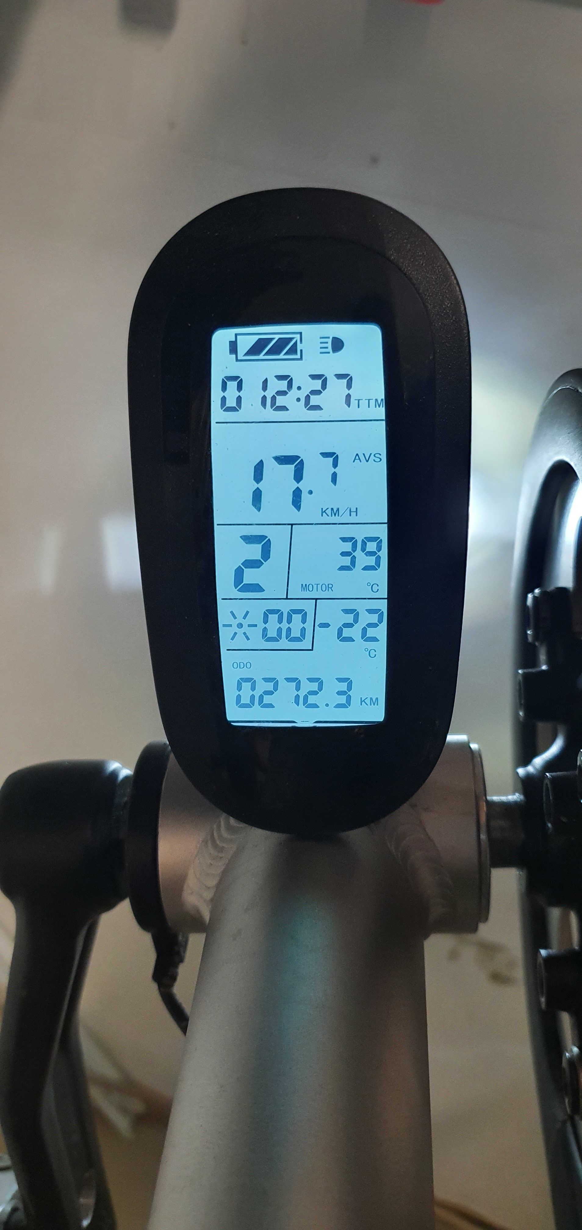
lcd6.jpg


Next phase i have plan to add some functionality to walk assist and cruise functions. I will to ask what is the suggested place to give or manipulate some fixed torque request by user while pressing a buttons?

Also in some point during dev the lcd6 out temp started to showing constant -22 C°
Did some one known which way it measures a temp? inside button enclosure there was a component printed "TEM".. perhaps that was a some short of thermistor? at least i have infinite resistance over it!

Best regards,
Tepa76
 
Tepa76 said:
Here is little summary what changes i had to make to get all this to work at this point

nice to get some fresh wind into the project!

The setpoint for the battery current is defined in the acasetpoint.c

If you want to add push assist or auto cruise, you have to define it there.

regards
stancecoke
 
Hello everyone, I am looking for software for the KT60SVPRCK-JLS02 (60V 45A) controller. Will this software work with this controller?
 
Two things you could check:
1. What microcontroller is the controller using?
2. Does it measure the phase current.

If it has a different microcontroller, this software can't be used.
If it's not measuring phase current, it won't work either.

Sometimes there is room for a phase measurement chip on the board, but the chip isn't mounted.
 
Hello , forum

I'm new here. Trying to get work OpenSource controller.
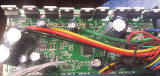
I have this one from ebay :

Controller1.PNG
Controller2.PNG

I flashed it succsefuly . Installed Bluosec at phone , connection is ok.
But motor does not start , no impulses at output. Throotle is ok , it can be monitored by Bluosec.
Tryed to measure by scope. Results : Here are PWM at High side , but no any impulses at low side .
I checked directly on cpu PINs , all three phases at high side has PWM , but on low side - no.
May some conditions are missing ? Checked brake , its "0"
What can be wrong ?

Br , Linas
 
I have checked ; Low side at cpu pins 20-21 , high at 26-28 ; looks good. I'm measure with scope directly on cpu pins , no any impulses at low side - 20-21 pins.
 
Schematic looks very similar. I can monitor by Bluosec ; voltage is ok , hall sensors is ok , then i rotate manualy its shows hall sensors , speed. Brake signal is ok. On this pcb are 2 low side mosfets in paralel and 1 for high.
 
Strange. What wave mode have you enabled?
Which sdcc version are you using?

regards
stancecoke

index.php
 
SDCC 3.9.0

https://github.com/stancecoke/BMSBattery_S_controllers_firmware

I tryed different sinus modes - no success.
 
Hm, ist there a half bridge driver on the PCB? What is the voltage on the Low Side controller pins?

regards
stancecoke
 
Yes, its looks to be HalfBridge . On low side pins ~2,5V , if i remember correctly.

PWM on HighSide is always on. Ontroothle i can see , that duty cycle chanching.

Can you in short write motor starting sequence ?
 
Can you check it exactly? The known hardware has no Half Bridge drivers, it has descrete boot strap circuits.
At standstill, Low and Highside have to have 50%duty cycle at 16kHz, so 2.5V with a simple meter on the pin ist OK.

regards
stancecoke
 
Im metering with Rigol scope . I will check later.
You mean measure on cpu pin by simple meter at duty cycle 50% must be half of supply voltage ?
 
Yes, half the time the high side is conducting, the other half the Low Side.
"Center aligned PWM"
 
Back
Top