Relay or solid state switch to turn on my 90v DCDC for lights safely

Joined
Feb 1, 2016
Messages
63
Hi,

I just tried to make a mosfet switch to turn on my DCDC for the bike lights. I wored it so that when the controller is turned on and 5v is present, it would open the gate for the full volts to the DCDC. I want to do this as my battery is 77v and the switches and relays are only up to about 28v DC.

I tried this and must have got the circuit wrong as I fried my Phaserunner. The Phaserunner and the Mosfet switch shared a ground, but the only other cable was the 5v throttle supply that i used for controlling the gate.

I've successfully used the IRF540n on a different controller:

https://docs.rs-online.com/54b2/0900766b801f1b4d.pdf

But had the issue when using the IRF1620G withe the Phaserunner:

https://docs.rs-online.com/54b2/0900766b801f1b4d.pdf

This is my wiring:
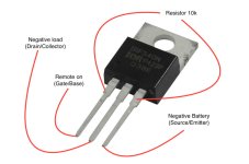
dsc_5395_1.jpg

I am going to buy another Phaserunner and i'd love to use this solution, but obviously i need to be 100% confident this won't fry it again!

Are there any other solutions for controlling high voltage DC with 5v? I need it to be small as it need to fit in the rear cavity of a cafe racer LED headlight. I also want it to be completely isolated from the high voltage Drain.

Thanks!
 
If you don't isolate the source using a gate driver setup, then anything that rings back thru the FET also goes bakc thru it's gate, and passes into the controlling device. Sometimes even with a gate driver it can happen, if there isn't enough isolation.

That's what often kills ocntrollers when there are phase shorts in motors or motor cables, or when there are poor phase connections that arc and generate RF. The stuff that goes back thru the FET gate kills the gate drivers, which may also fail shorted and pass that back thru to the MCU. But usually the gate drivers stop the spikes/etc from getting back to the controlling source.


Because of that type of potential problem, I would strongly recommend against using your controller to switch this, even with a gate drive, because as you have seen, the consequences of a failure can be dire. :(

Instead, if you use a simple voltage divider on the battery voltage, with very high resistance to limit current and power wastage, calculated so the voltage range at it's center point is always within the range to safely power a typical 5v regulator, you can then use that to power the gate driver circuitry for the FET.

If the voltage range of your battery from full to empty is too large to do a simple voltage divider, you might want to instead use a different DC-DC for the lights that has a "remote" switch line that is easier to control it with, rather than just it's main power.
 
5V usually is 2 low as gate voltage for such a power mosfet. They usually need 10 - 12V to become fully conductive.
This might not matter much for a light as the current passing trough the fet will be low. Just measure the Drain Source voltage in it's on state to see if it's fully turned on. (Should be close to 0V) If you look at a controller schematics you will see that they use 12V to drive the power mosfets.
 
Some of the available gate driver chips may have the boost dc-dc required to create the necessary voltage and current.

But there are also FETs out there that can be driven directly from 5v (though you should sitll have appropriate gate drivers to prevent damage to the device controlling them).
 
I was under the impression that the main purpose of gate drivers is to guarantee fast switch on / switch off times. A power fet heats up during it's transition from on to off and the other way around. The gate of a power mosfet is basically a capacitor that needs to be charged / discharged. Most microcontrollers have 3V3 io lines, the older ones 5V io lines. Those io lines can't produce enough current to charge / discharge the gate of the power mosfet rapidly. Another feature of (some) gate drivers is that they protect the system against simultanously turning on the upper and lower stage of a H bridge as that situation shorts the supply to gnd directly.
If you start from a 36 or 48 v battery, it's probably easier and more efficient to lower that voltage to 12V for the gate drivers. Not saying gate drivers with buildin stepup don't exist, but you likely won't find them often in brushless controllers for ebikes.
 
I just leave mine permanently plugged in and ON. it doesn’t seem to drain the battery noticeably.
 
obcd said:
I was under the impression that the main purpose of gate drivers is to guarantee fast switch on / switch off times.
That's a part of it.

But they are also there to protect whatever controls the gates. With nothing between it, then any FET failure, or any ringing that sends signal back thru the gate, will directly affect whatever is connnected to the gate, and if it's a shorted FET failure, it can easily pass the full voltage of whatever teh FET is switching back thru the gate into that device.

That's usually a POOF! failure of that device at that point.

With a sufficiently isolated gate driver, the controlling device is safe from whatever happens on the other side.

If you start from a 36 or 48 v battery, it's probably easier and more efficient to lower that voltage to 12V for the gate drivers. Not saying gate drivers with buildin stepup don't exist, but you likely won't find them often in brushless controllers for ebikes.

No, you wont find them at all in the generic controllers--that stuff is almost always discrete components. In high end controllers you likely wont' find them either because they may have a separate supply just for the gates and such.

But they exist (or at least used to), specifically for driving power FETs from low-level logic/etc circuitry, and you could use them for this purpose, which has nothing to do with the controllers. ;)
 
Back
Top