Harold in CR
100 kW
I forgot this was a brushless DC controller brain as I wanted an induction motor set up. Sorry.
Harold in CR
Harold in CR
amberwolf said:arber333 said:Also 2us for automotive power section seems small. I use 3.1us with Volt inverter. I broke two Volt inverters using 1.8uS because i mistakenly calculated my deadtime. Better have some holes in PWM signal than in IGBTs i say.
If you're referring to Kiwifiat's post up above:
I am presuming his is based on experience/usage with this same system (though I don't know with what kind of motor)...but I'm all for safer rather than sorrier.kiwifiat said:Because IGBT's are slow in comparison to mosfets we need to set deadtime to 2000ns and pwm frequency to 6kHz.")

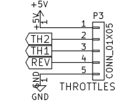
amberwolf said:Is there a particular reason the throttle *must* be powered by the brain board itself, and not an external 5v?
amberwolf said:AFAIK, if I connect them, it will cause a conflict between the two slightly different 5v voltages, and potentially damage one or both 5v supplies?
This is why the CA v3 throttle signal to the present generic controllers doesn't use the 5v either, only ground and signal.
The ebrake (a hall-based cable-operated throttle pulled by a brake lever) is also powered by the CA's 5v, so it also doesn't use the 5v from the brain.
Additionally, since the two HIL's, once completed, will both share the same throttle and ebrake signals, then even if I were powering ebrake/throttle from the brain, I would only use *one* of the brains' 5v lines to power them, and not tie the 5v lines together? (just hypothetical, since I will still be powering both ebrake and throttle from the CAv3).
Ok. Just making sure I hadn't missed something.kiwifiat said:That was not the point of the post. The throttle *must* be powered in order for the controller to function and none was shown. Now that you have updated your schematic there should be no room for errors.
This project has been a little more complex than anticipated, partly because all of the information I needed was not all in one place, in a clear, obvious format (which is what I'm trying to fix with this thread). Good. The CAv3 doesn't output anything more than that range, so it should be safe.Correct , you only need a common ground between the controller and the power source for the throttle and to limit the throttle output voltage to the range between 0-5V.
amberwolf said:The same is true of the BobC buildup-and-test document; there's a number of things I think he simply didn't get to write before he died. This is another document I hope to perfect for others to use, but will probably need feedback on it as I go.
amberwolf said:At present it is still set for the standard hall-throttle output range for the generic controllers still running the trike. I'll make a new setup for it that uses the full 0-5v output range once it's running the HILs...or maybe just use a second CA entirely since I have a spare, and just swap it out, keeping the other one with me to swap back if I run into problems.
kiwifiat said:You could update the current docs but as I have said elsewhere there is a new BobC schematic and board layout. I have had some boards made at OSH Park and am testing an assembled one now. Once the testing phase is complete Whereswally606 will post the updated schematics, gerbers and build instructions then.
Ok. My only thought was that control resolution would be better using the full voltage range, but I don't know that it matters.That would be entirely unnecessary as the Lebowski brain is far too smart to need that and will run perfectly on a HALL effect throttle. In fact if you had a throttle that put out say from 0.5 to 3V you would be able to calibrate it to function just as well as any other throttle. The only limitation is that you do not exceed the 5V maximum.


 .
. 
Thanks for your great thread about mating the Lebowski controller to the Honada IMA inverter.
This is just what I needed for my electric ATV build. The Heinzmann PMS120 motor I am using can tolerate a lot of current and a power stage for that is rather expensive and not trivial to design.
I just finished building a Lebowski controller on a board I had laying around, upgraded it to version 2A1, and the Honda IMA inverter is supposed to arrive tomorrow,
Could you be so kind and let me know the parameters that will work with the IMA inverter. I saw PWM frequency and dead time mentioned in the thread. But how about the current sensors and other pertinent values?
amberwolf said:I've been measuring all over the PCB (not every single point, but at least a hundred so far, most of them unlikely but ran out of likely ones), and still have not found a place I can connect to for battery voltage so the brain board can measure the battery voltage. Either I've just missed it, or I'm doing something wrong.
So at this point I'll need to setup a large ring terminal on a thin wire to go to the battery voltage measuring pin (BAT), via the Rmeas resistor, on the brain board, and then that ring terminal has to go outside the casing to be bolted along with the battery positive wire to the POS terminal on the outside of the casing. I was really hoping to avoid this.

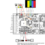
 In this photo coleasterling took of the back of the board it looks like there is a big enough gap between the components on the other side of the board and the white rectangles to make a cut. Just need to make sure not to go near the driver board underneath the main board. I will cut the two gate supply traces going to each 3 rectangles with a sharp razor blade to avoid damage though.
thoroughbred said:what is the best vintage of used IMA inverters to buy? most of the listings are for 2010-2014 cars which look different from what is documented here. I want small, powerful and simple