TSDZ2 EBike wireless standard (like Specialized Turbo Levo) - OpenSource

Headless said:
@casainho - Can I just check one thing? What is the voltage of the TSDZ2 motor-controller's UART?

Given the brake input is pulled up to 5V I would have assumed that the procesor was running at 5V, but 3.3V seems to be the correct voltage for flashing it? The nRF52840 does not have 5V-tolerant GPIO when running at 3.3V and I can't find any mention of protection diodes to the power rails, which might be the case if they want to save every picowatt? It would make the GPIO rather vulnerable to :bolt: :flame: though....
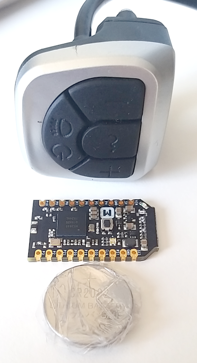
It is 5V on TSDZ2. SW102 is 3.3V as also 860C. This displays have resistors in series on the lines... And In sure the TSDZ2 also has resistors in series on the lines.

I will try by myself and I have 2 extra boards in the case...
 
Just worries me that the nRF52840 manual doesn't mention GPIO input diodes like most older products have, in which case a simple resistor current-limiter may cause problems for reliability. A couple of voltage-dropper diodes in line would also do the trick, but I'll wait to hear back from you.
 
Apologies - it's not in the manual, but someone has already asked the question on the Nordic Forum. They have Schottky diodes, hence the VDD+0.3V limit on the GPIO input voltage - why they didn't explain it explicitly I don't know..... So a simple resistor will do. No idea what value though, if the TSDZ2 already has inline resistors in the UART?
 
Headless said:
Apologies - it's not in the manual, but someone has already asked the question on the Nordic Forum. They have Schottky diodes, hence the VDD+0.3V limit on the GPIO input voltage - why they didn't explain it explicitly I don't know..... So a simple resistor will do. No idea what value though, if the TSDZ2 already has inline resistors in the UART?
I don't remember but maybe 100, 47 or 33R.
 
casainho said:
I don't remember but maybe 100, 47 or 33R.

100R would allow 14mA (by my reckoning) into the GPIO Schottky protection-diode, which is a bit much. I guess 2K would be fine - you can always reduce it if it seems like there are reliability issues.
 
casainho said:
The idea is to make a quick and dirty board, less components possible and soldering required, so less barriers for new users. This board will be DIY so the success of the project will depend on the easy to source and build!!

Hey casainho, i don't know if you are familiar with these days possibilities. There are manufacturers like JLCPCB or PCBWAY (not sponsored). This manufacturers can do PCB+SMT for small quantities like 5pcs. One thing you have to do is to upload gerber file (PCB project) and BOM (Bill of materials) and CPL (X Y coordinates for components) files. They have their own components database / shop to choose from (30 000 components). I am using their services a lot and i'm very happy.

I'm writing this to let you know that PCB+SMT can be made by proffesional manufacturer in reasonable price so there is no barriers for new users :) If you will choose components from the beginning from their database - you will end up in very easy to get product.

Just look at their services here: https://jlcpcb.com/smt-assembly

Examples of ready products from them you will find on YouTube by many users.
 
bikelpl said:
casainho said:
The idea is to make a quick and dirty board, less components possible and soldering required, so less barriers for new users. This board will be DIY so the success of the project will depend on the easy to source and build!!

Hey casainho, i don't know if you are familiar with these days possibilities. There are manufacturers like JLCPCB or PCBWAY (not sponsored). This manufacturers can do PCB+SMT for small quantities like 5pcs. One thing you have to do is to upload gerber file (PCB project) and BOM (Bill of materials) and CPL (X Y coordinates for components) files. They have their own components database / shop to choose from (30 000 components). I am using their services a lot and i'm very happy.

I'm writing this to let you know that PCB+SMT can be made by proffesional manufacturer in reasonable price so there is no barriers for new users :) If you will choose components from the beginning from their database - you will end up in very easy to get product.

Just look at their services here: https://jlcpcb.com/smt-assembly

Examples of ready products from them you will find on YouTube by many users.
Thanks, I know, because TSDZ2-ESP32 project is doing just that: https://github.com/TSDZ2-ESP32/TSDZ2-ESP32-Wiki/wiki

But the thing is that I do not want to be selling boards and the process for a final user to buy a board seems complex: https://github.com/TSDZ2-ESP32/TSDZ2-ESP32-Wiki/wiki/How-to-get-the-PCB

I still think that a DIY and quick and dirty board is a smaller barrier than a professional board. But alternatively would be nice if someone would want to do that same job as TSDZ2-ESP32 project in providing the board and collecting the Referral Program money incentives.
 
@casinho - My brain is grinding to a halt! The https://opensourceebikefirmware.bit...eets_and_application_notes--STM8S105S4T6.html datasheet shows that @V.DD = 5V, the STM8S105 V.IH Min = 0.7 x V.DD == 3.5V :warn: Which are CMOS levels, so a 3.3V output from the VLCD5 (or any other device) should not register as high, rather as "noise" which would cause undefined behaviour. If the LCDs definitely run at 3.3V, I must be missing something? :confused:

Looking at the photos on https://opensourceebikefirmware.bit...heng_TSDZ2_mid_drive_motors--LCD_-_VLCD5.html shows a couple of resistors in the VLCD5 UART as you mentioned. Do you have a close-up photo of the front of the motor-controller PCB, by the Tx/Rx connectors, so I can see if there's any level-shifting circuitry? There are good photos of the back of the PCB, but all the photos of the front have wires and epoxy in the way. Sorry this is turning out to be a bit more complicated than I had anticipated.......
 
Headless said:
@casinho - My brain is grinding to a halt! The https://opensourceebikefirmware.bit...eets_and_application_notes--STM8S105S4T6.html datasheet shows that @V.DD = 5V, the STM8S105 V.IH Min = 0.7 x V.DD == 3.5V :warn: Which are CMOS levels, so a 3.3V output from the VLCD5 (or any other device) should not register as high, rather as "noise" which would cause undefined behaviour. If the LCDs definitely run at 3.3V, I must be missing something? :confused:

Looking at the photos on https://opensourceebikefirmware.bit...heng_TSDZ2_mid_drive_motors--LCD_-_VLCD5.html shows a couple of resistors in the VLCD5 UART as you mentioned. Do you have a close-up photo of the front of the motor-controller PCB, by the Tx/Rx connectors, so I can see if there's any level-shifting circuitry? There are good photos of the back of the PCB, but all the photos of the front have wires and epoxy in the way. Sorry this is turning out to be a bit more complicated than I had anticipated.......
Don't worry. The TSDZ2 VLCD5 and KT-LCD3 work with 5V but the 850C, 860C and SW102 work with 3.3V (and TSDZ2 is sold also in combination with 850C display).

Do you want another quick challenge? - draw the schematic for reusing the VLCD5 keypad, for being a wireless remote button. The wireless board will need to work with a small cell button - how can this be done is a quick and dirty way?
 
casainho said:
Do you want another quick challenge? - draw the schematic for reusing the VLCD5 keypad, for being a wireless remote button. The wireless board will need to work with a small cell button - how can this be done is a quick and dirty way?

Wouldn't the easiest be to use another lower spec nRF product? I assume you mean a self-contained Bluetooth button using the VLCD5 keypad, a Bluetooth GPIO processor and a button cell? Easy to wire up, I'll leave the programming to you - making it neat would be an issue! Perhaps the brakes could connect to it as well? Let me know what module and I'll check it out.
 
Headless said:
Wouldn't the easiest be to use another lower spec nRF product? I assume you mean a self-contained Bluetooth button using the VLCD5 keypad, a Bluetooth GPIO processor and a button cell?
There boards on ebay that are a bit smaller but have the NRF51xx, I have some with me. But that would mean a different firmware development and different stock of that boards - it is much easier to keep the same board stock and firmware development (like I wish to reuse the SW102 code but that is not so easy because it must use an older Nordik softdevice version because of the microcontroller different version... - also the smaller board are harder to solder the pins, this one is nice and have a nice size for pins and not much bigger than the battery - can be put under the buttons, on a 3D printed base or simple as a small box on the cable:

image.png


Headless said:
@casainho - would this be useable? https://www.aliexpress.com/item/32845674676.html I don't know if the nRF52832 is current model?
Could be but I can not find it on ebay, meaning it may be more hard to source. Also, it is not a dev board, there are no documentation nor code examples. Also, seems to not have voltage regulator, so, harder and high risk to DIY.
 
Headless said:
casainho said:
it is much easier to keep the same board stock and firmware development
Do you mean like this?
About the board you linked, costs 14€. The dev board I am using costs 12€!! - https://store.makerdiary.com/collections/frontpage/products/nrf52840-mdk-usb-dongle

About the remote buttons:
1. the battery, do you know if is a direct connection like that?
2. the buttons, do you think they use much current?
3. the brakes, do you say they use much current. The ones I use, magnetic sensor, seems to be a red switch, they only have 2 wires...
And I don't know if the brake signal latency will be ok for brake the motor in time... let's try. If they work and do not use much current, then I think this is the best idea ever!! - I would then wire the TSDZ2 brake wires to the wireless board. Then, we could also have a wireless throttle!! (if brakes work, throttle would also work, right?).

For buttons, later I would like to try to have a remote buttons with 6 or 7 buttons, 3 buttons to control TSDZ2 (probably Bluetooth for better latency?) and other 3 buttons to control the GPS cycling computer (maybe ANT+) (on Garmin Edge, to quick change between main screens, just like now I change the 860C main screens clicking on the on/off button).
 
casainho said:
1. the battery, do you know if is a direct connection like that?
2. the buttons, do you think they use much current?
3. the brakes, do you say they use much current.

1. I think so, but I can't find the part number of the tiny DC-DC converter. Do you have a microscope? :D There seem to be various ways you can use the internal PSU on the nRF52840 to increase efficiency. CR2032 etc. all seem to work down to 2V, and the nRF52840 runs down to 1.7V - I've made a note of the Nordic recommended battery voltage monitor (2x R + 1x C) which uses picoamps....
2. Normally you would scan the buttons slowly until you pick up an input and then scan them faster until there's no input for n seconds. I suppose you could turn off the internal pull-ups between scans, but maybe the processing to do that would use more energy than leakage into the pull-ups? Also, see 3. below.
3. For brakes I suppose you'd want to use interrupts - I can't imagine the curernt used would be significant, and it might be quicker and more efficient than scanning.

It would be interesting to measure it in-circuit, but you'd need a higher-resolution DVM than mine, as it doesn't do less than 1mA with any kind of accuracy. :roll:
 
With battery voltage monitoring circuit and brakes on one input - leaves 2x GPIOA and 2x GPIO. The two NFC DIOs have other components connected to them, so not ideal for buttons.
VLCD5_nRF52_Buttons_V2.png
 
casainho said:
1. the battery, do you know if is a direct connection like that?
Having re-read the datasheets and trawled through Mouser, I think the Buck IC is one of these https://www.monolithicpower.com/en/mp2148.html. When the Vin drops below Vout (3.3V on the dongle) the Fet output is permanently switched on, which is okay with ~3V cell, but the under-voltage lock-out is ~2.5V and will waste some battery capacity (I don't know what %). The better thing to do would be to de-solder the IC and connect the battery to the 3V3 "output" terminal. This is how some of the bigger boards do it https://infocenter.nordicsemi.com/i...2840_dk/UG/nrf52840_DK/vdd_power_sources.html.
 
casainho said:
Thanks, I know, because TSDZ2-ESP32 project is doing just that: https://github.com/TSDZ2-ESP32/TSDZ2-ESP32-Wiki/wiki
I'm guessing everyone is starting to get busier as things come back online, so is there any merit in using the ESP-32 Android App as starting point, to save on duplication? Just out of curiosity, I'm going to install Android Studio when I can find my Windows laptop and have a look. Don't expect anything! :wink:
 
Headless said:
casainho said:
Thanks, I know, because TSDZ2-ESP32 project is doing just that: https://github.com/TSDZ2-ESP32/TSDZ2-ESP32-Wiki/wiki
I'm guessing everyone is starting to get busier as things come back online, so is there any merit in using the ESP-32 Android App as starting point, to save on duplication? Just out of curiosity, I'm going to install Android Studio when I can find my Windows laptop and have a look. Don't expect anything! :wink:
Android Studio, works on Linux (and MAC also, I think).

I don't know what is easier, anyway, myself I could write a quick and dirty app for basic control and configurations, but that would take a lot of time, better if other developer can do it.

I do not expect anything more than a main screen showing bicycle speed, etc, like on 860C display but without graphs. And the configurations. Nothing more, complex things like navigation and fitness features should be used on the cycling computers like Garmin Edge.

I am still looking ANT+ code to understand how I will implement it and looking at Visual Code Studio IDE for debugging with JTAG, instead of Eclipse that I am using currently.
 
casainho said:
@raw, do you have any news on the mobile app?

I am being thinking on the structure on the firmware from my side and sure it will need the configurations done on the mobile app...

im still alive!

glad to see some progress on the hardware side here, so here are my thoughts on some topics:

  • * i have not continued to work on my mobile app in the meantime, but i will do now. if you implement the json-based configuration interface i have described earlier, i can develop my app directly against it.
    * @Headless: compared to the ESP-32 APP the new one will run on ios and android, will be easier to maintain (thanks to flutter) and receives configuration structure from the dongle instead of having it hardcoded in the app, which allows adding/removing/modifying configuration options on the dongle firmware without updating the android app.
    * Power Switching: its nice that you wrap your brains around that Problem - but a simple switch on the battery would be easier and more energy efficient. I use a hailong battery from ebay that has a switch integrated. i also expected that the dongle can be directly powered by the 5V display power line coming from the motor, so no step down conversion would be needed. The dongles VIN is 5V resistant AFAIK.
    * Can you add the possibility to use the 860C display to you considerations? i think i want to keep it. passing the packets from the motor to the display should not add much effort to this project right? It can be just used as added ANT+ and bluetooth functionality while keeping the existing display setup and buttons. i think the configuration packets from the display could be ignored, as we then have the android app.
    * for the buttons topic: i still think the most easy way would be to use some cheap "bike media button" (7€) and connect them via bluetooth to the dongle. im sure the media signals from the buttons can be remapped to assist up/down and any function we want. i also expect the batteries of these devices to run for months, if not years. why do you not consider this solution?
    * @Casainho: for an nice IDE, you can take a look at IntelliJ CLion. OpenOCD and stuff is supported. We are using Jetbrains products for different languages at work with great pleasure. They offer a 30 Day trial.

@Casainho: i bought a Garmin VivoActive4 for me and my wife, so now i am in the I-Want-My-Cycling-Power-In-My-Garmin-Stats-Boat too!

Edit: i think we will also need some bluetooth interface to pass bluetooth/ant scanning/paring functionality to the app (like scanning for wireless buttons).
 
raw said:
casainho said:
@raw, do you have any news on the mobile app?

I am being thinking on the structure on the firmware from my side and sure it will need the configurations done on the mobile app...

im still alive!

glad to see some progress on the hardware side here, so here are my thoughts on some topics:

  • * i have not continued to work on my mobile app in the meantime, but i will do now. if you implement the json-based configuration interface i have described earlier, i can develop my app directly against it.

  • Good you are still alive :)

    I never used JSON and I found that Nordic SDK uses this JSON C library: https://github.com/DaveGamble/cJSON
    So I think we can assume will be possible to do that as you suggested.

    raw said:
    * @Headless: compared to the ESP-32 APP the new one will run on ios and android, will be easier to maintain (thanks to flutter) and receives configuration structure from the dongle instead of having it hardcoded in the app, which allows adding/removing/modifying configuration options on the dongle firmware without updating the android app.
    This seems powerful!! When developing the firmware, I will not need to keep changing the mobile app, build it and test - will make development much faster.

    raw said:
    * Power Switching: its nice that you wrap your brains around that Problem - but a simple switch on the battery would be easier and more energy efficient. I use a hailong battery from ebay that has a switch integrated. i also expected that the dongle can be directly powered by the 5V display power line coming from the motor, so no step down conversion would be needed. The dongles VIN is 5V resistant AFAIK.
    1. the original TSDZ2 does not work like that, a battery switch to power off. I think users do not expect that. Also that would have the risk to user forget the motor controller turn on but with the digital switch we will have a timeout as safety feature.
    Also, some batteries does have that switch, my 4 batteries does not.

    2. There are no 5V lines, I am pretty sure.

    raw said:
    * Can you add the possibility to use the 860C display to you considerations? i think i want to keep it. passing the packets from the motor to the display should not add much effort to this project right? It can be just used as added ANT+ and bluetooth functionality while keeping the existing display setup and buttons. i think the configuration packets from the display could be ignored, as we then have the android app.
    The issue with this idea is that will require even more work: for the wireless board firmware, I see it working as being a "wireless virtual display" and so adding the possibility for external display means having 2 displays on the system, it will be for sure complex to implement....

    raw said:
    * for the buttons topic: i still think the most easy way would be to use some cheap "bike media button" (7€) and connect them via bluetooth to the dongle. im sure the media signals from the buttons can be remapped to assist up/down and any function we want. i also expect the batteries of these devices to run for months, if not years. why do you not consider this solution?
    I am more interested in DIY my own buttons but I will buy 2 units of that Bluetooth buttons for testing. I hope we can have ANT+ and Blueooth buttons working.

    raw said:
    * @Casainho: for an nice IDE, you can take a look at IntelliJ CLion. They offer a 30 Day trial.
I will keep using Eclipse and Code Visual Studio, they are also very good, popular, OpenSource and free - will work for anyone, no limitations.

raw said:
@Casainho: i bought a Garmin VivoActive4 for me and my wife, so now i am in the I-Want-My-Cycling-Power-In-My-Garmin-Stats-Boat too!
So you will be able to control your TSDZ2 from your watch:


We need to develop our own app, because that one seems to just read data from the Ebike and does not control the assist level, etc.

raw said:
Edit: i think we will also need some bluetooth interface to pass bluetooth/ant scanning/paring functionality to the app (like scanning for wireless buttons).
Yes, I forgot that.
 
raw said:
so here are my thoughts on some topics:

That's a lot to process! :shock:

raw said:
compared to the ESP-32 APP the new one will run on ios and android,

You guys are both cheating - it sounds like you've done this before!

raw said:
a simple switch on the battery would be easier and more energy efficient. I use a hailong battery from ebay that has a switch integrated. i also expected that the dongle can be directly powered by the 5V display power line coming from the motor

My battery has a switch as well, but in all honesty I'm tempted to link it out as it looks way too small for 20+ Amps. There is no dedicated display supply - the 5V is only there on the throttle version to power the potentiometer. I would suspect that you wouldn't be able to draw much current and could even crash/brown-out the motor-controller if you weren't careful. If you want, you can just join the green and white wires together (I think?) and then when your battery is switched on the motor-controller will be live.

raw said:
Can you add the possibility to use the 860C display to you considerations?

Would this be a problem? I mean, the motor-controller will still be spitting out all the data the LCD expects anyway, so all you would need to do is split the output from the motor-controller to both the 860C and the Dongle and leave the output from the 860C UART disconnected. If Bluetooth/ANT+ buttons are used ,the Dongle will send the commands to the motor-controller instead of the 860C's buttons. Have I got this wrong? I am assuming that the motor-controller firmware will stay as it is. This might even help with debugging?

raw said:
bluetooth interface to pass bluetooth/ant scanning/paring functionality to the app

You're starting to get a bit meta now! It all sounds really exciting and like you've both firmed up what is possible and desirable in the solution. I'm impressed at just how big an eco-system this is becoming, and what pros you are! :bigthumb:
 
Okay, I didn't think about how the 860C would write any config. changes to the motor-controller. :oops: I guess the basic information would still be good and updated on the main page, but.....

I guess the only way to do it would be to copy the ESP-32 board and have a dual-UART. As far as I can tell from the datasheet for the nRF52840 it does have two UARTs, both of which are EasyDMA capable, but one of which can be used "conventionally". So I guess the option is there. Could "someone" :) rewrite the 860C firmware to copy how the App pulls the structure from the dongle?

It's interesting in that you could have three screen options (ANT+ LEV, Android App, 860C) and three button options (ANT+, Bluetooth, wired via 860C). Maybe too much choice?
 
ah ok, i thought the display was running on 5v already.. but yes it runs on battery voltage which means we need to have a step down conversion.

Headless said:
Okay, I didn't think about how the 860C would write any config. changes to the motor-controller. :oops: I guess the basic information would still be good and updated on the main page, but.....

I guess the only way to do it would be to copy the ESP-32 board and have a dual-UART. As far as I can tell from the datasheet for the nRF52840 it does have two UARTs, both of which are EasyDMA capable, but one of which can be used "conventionally". So I guess the option is there. Could "someone" :) rewrite the 860C firmware to copy how the App pulls the structure from the dongle?

It's interesting in that you could have three screen options (ANT+ LEV, Android App, 860C) and three button options (ANT+, Bluetooth, wired via 860C). Maybe too much choice?

the dual uart solution is what i had in mind, passing the packages from the motor to the display so it can show the current values on the main screen and ignoring any configuration updates coming from the display (for now) except some state changed caused by the buttons (assist level for the start). having configuration updates from the display processed would really cause some complexity (and conflicts) we do not need. also, the display would be fully optional... so if you loose the connection to the display, things still work.

i think having the display still supported will make this project a pure upgrade without any drawbacks (loosing the display if you want to keep it, everyone already has one). im not saying this is #1 priority, but when designing wiring, circuits and code, keep that possibility in mind.
 
raw said:
the dual uart solution is what i had in mind, passing the packages from the motor to the display so it can show the current values on the main screen and ignoring any configuration updates coming from the display (for now) except some state changed caused by the buttons (assist level for the start). having configuration updates from the display processed would really cause some complexity (and conflicts) we do not need. also, the display would be fully optional... so if you loose the connection to the display, things still work.

i think having the display still supported will make this project a pure upgrade without any drawbacks (loosing the display if you want to keep it, everyone already has one). im not saying this is #1 priority, but when designing wiring, circuits and code, keep that possibility in mind.
I agree with the idea of keep supporting the 850C/860C and SW102 displays, connected or not to the wireless board. The thing is that it makes the project more complex to achieve on a first version and put more pressure on me, more stress and I hate it, so, I will not do it in a first step.

For the first version 0.1.0, the minimum for have something that works is implementing only ANT+ LEV. Not even the buttons for changing assist level should be needed and the ones used are the ones from the GPS cycling computer - for testing during development I have my own GPS Garmin Edge 830. The mobile app is needed to change the motor configurations, just like currently in what is done on the display.

After having a first version, then other features can be added but it is overwhelming, at least for me, considering the small amount of time I have available - it is stressful to being talk of much things to do and know that almost nothing is being implemented in practice.

About the firmware, I now fully understand the Nordic sample code for ANT+ HR and the next step is to implement LEV following the same structure.
 
Back
Top