Hello! I hope this is not too off-topic. Earlier in this thread there was
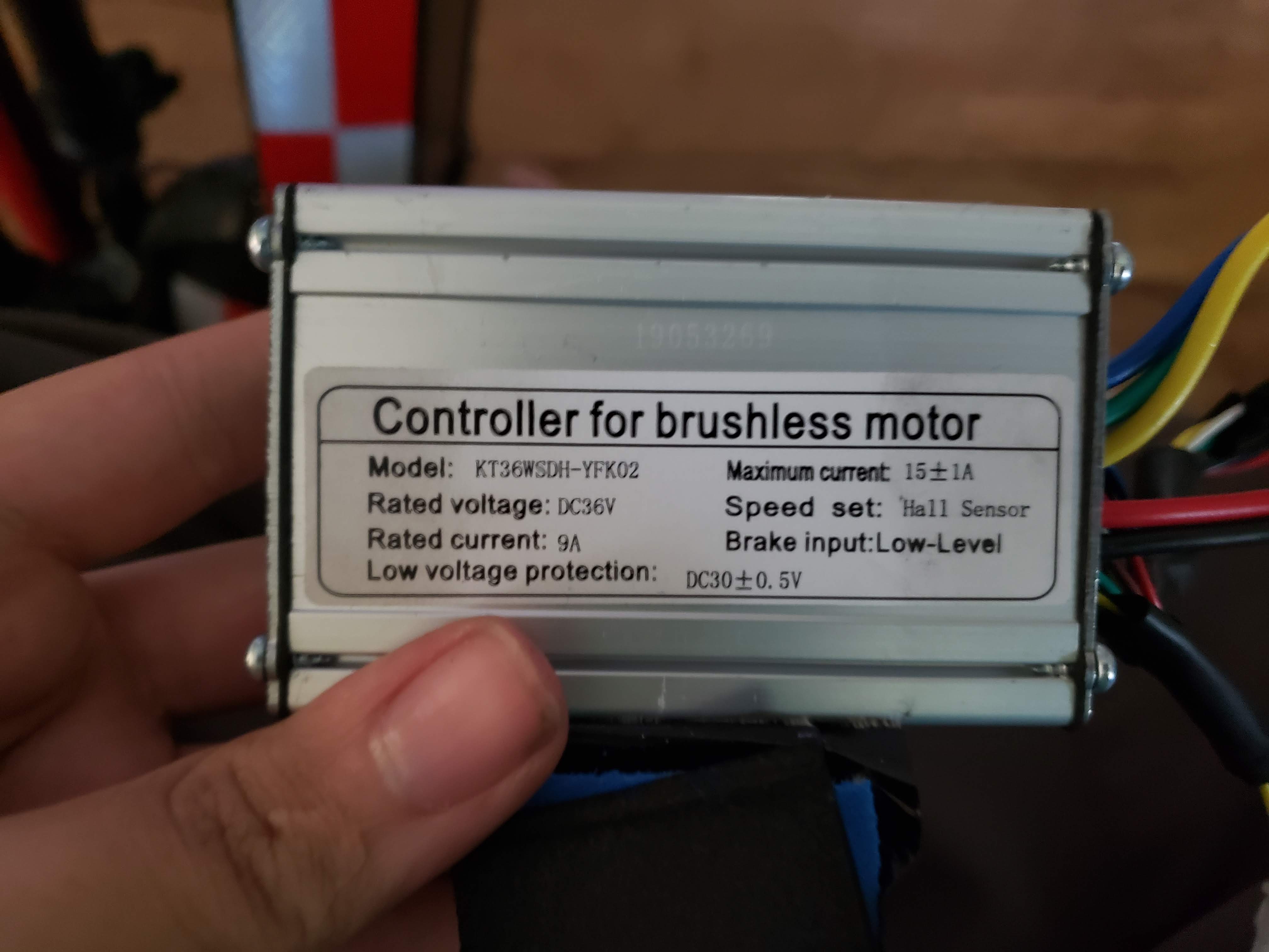
a mention of a similar KZQW22A controller, which I also have. The most annoying thing about that controller is that there is a hard power cutoff after 25km/h which makes the riding experience horrible. That is, there's no PID or anything like that to keep the speed at 25km/h, it just stops assisting altogether once you reach the speed. Thanks to the help from
Aleksandr Boldin we managed to reverse-engineer the firmware and remove the speed limit (in my country there's no speed limit for 250W bikes anyway). The bicycle didn't get significantly faster (it can only reach around 30km/h without the software limit), but the riding experience is much better now. I've been using it for a few months without any issues.

I'm attaching the modified firmware which you can flash if you have the same controller with the same firmware. Original firmware is also attached.
Here are some helpful notes:
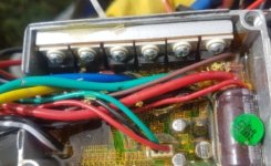
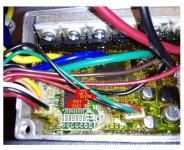
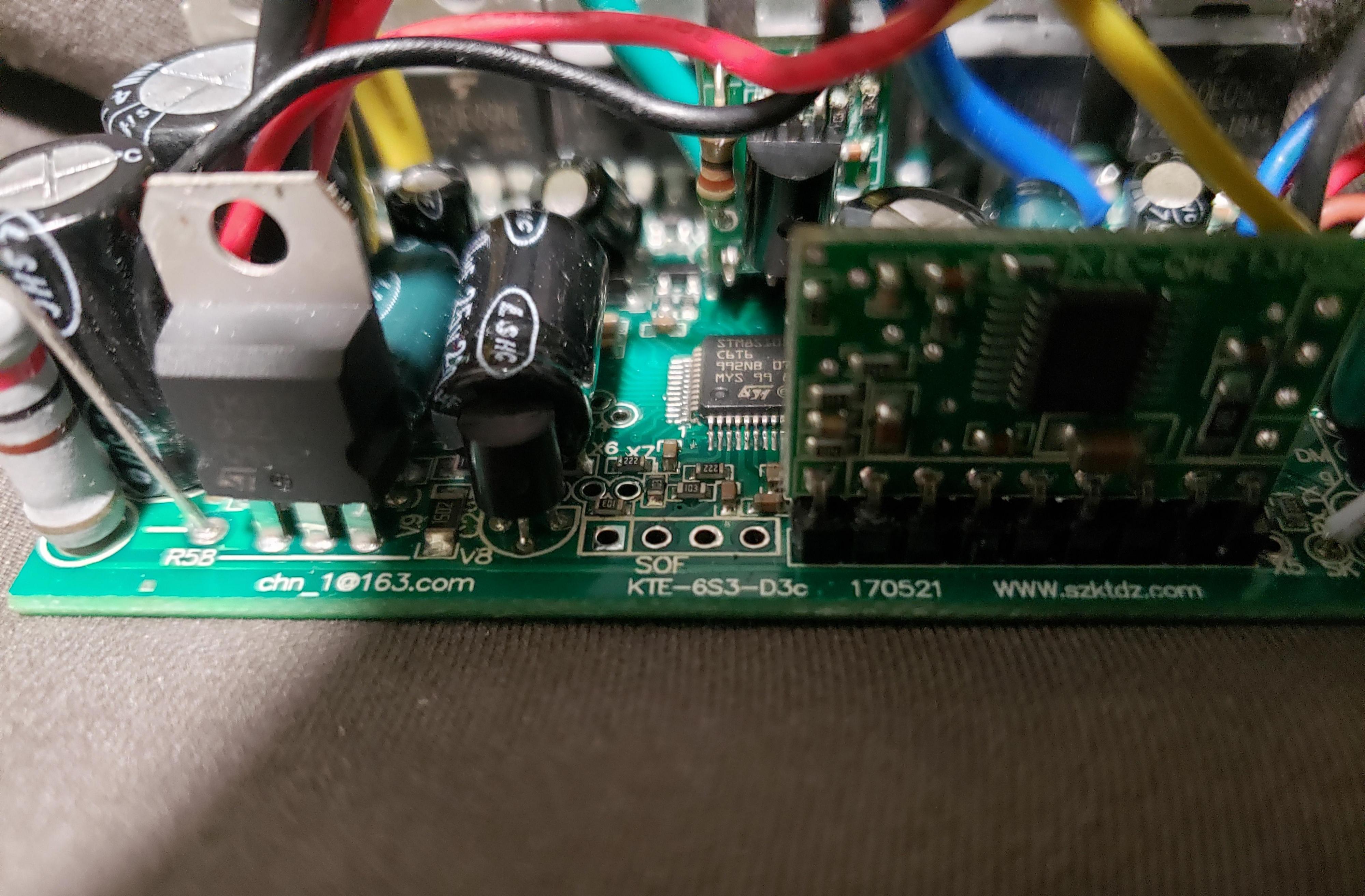
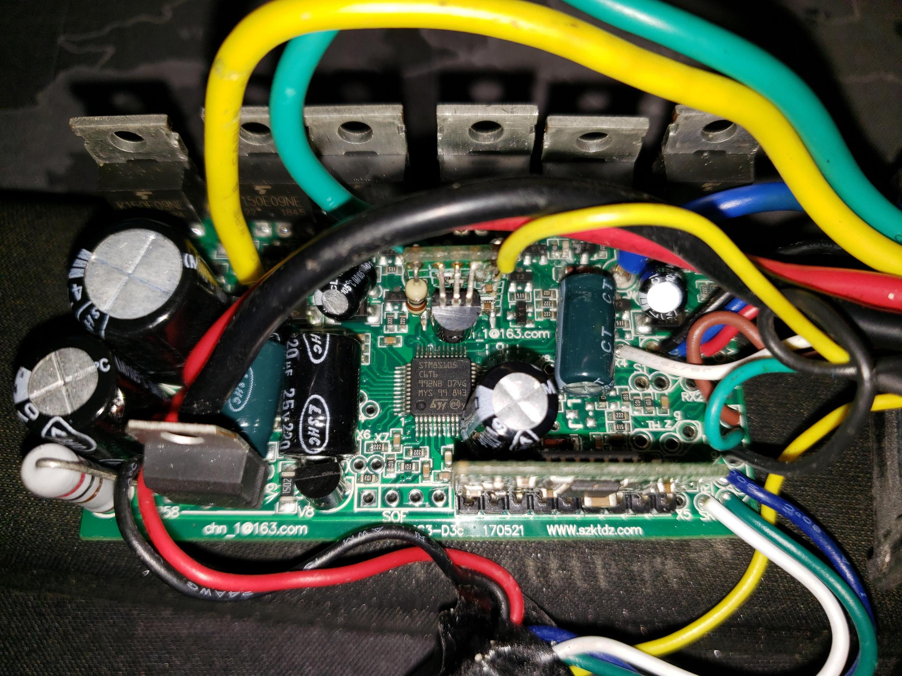
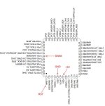
Programming connector:
Code:
black – GND
yellow – SWIM
blue – Reset
red – maybe VCC, you don't need it
To read data from the microcontroller (assuming you use stlink v2):
Code:
./stm8flash -c stlinkv2 -p stm8s105s4t6c -s flash  -r KZQW22A-flash.bin
./stm8flash -c stlinkv2 -p stm8s105s4t6c -s eeprom -r KZQW22A-eeprom.bin
./stm8flash -c stlinkv2 -p stm8s105s4t6c -s opt    -r KZQW22A-opt.bin
To write the firmware:
Code:
./stm8flash -c stlinkv2 -p stm8s105s4t6c -s flash -w KZQW22A-flash-hacked-double-speed-limit.bin
Good luck!