Tsdz2 firmware open source adapted to vlcd5, vlcd6 and xh18

psl2806 said:
.....Does the motor stop to soon or too late on an empty battery or does it only have effect on the display where it show how full the battery is?

I still would like to learn how to measure the battery resistance.....
I never found this resistance important, so have used the default value always. I think there will be no much difference with a full batterie, but maybe with the last bar a bit.

If you want to measure it, you can try to use the data readings of the display,
First measure the voltage when standing still and than again with riding the bike with a lot of motor support.
Try to keep the motorsupport (=measured current) as constant as possible. Calculate the Voltage drop by subtracting the two Voltage values en divide this value by the current.
 
Elinx said:
I never found this resistance important, so have used the default value always. I think there will be no much difference with a full batterie, but maybe with the last bar a bit.
I believe the purpose of the internal resistance value is to prevent the battery bars to flash between two states. Let's say you have just enough voltage to show 4 out of 6 bars and then you start pedaling pulling 10A from the battery. With an internal resistance if 0.2ohm that will drop the voltage by 2V and unless the code compensates for that your battery bars would go down to 3 out 6 bars and then when you stop pedaling it would return to 4 out of 6 again.

If you want to measure it, you can try to use the data readings of the display,
First measure the voltage when standing still and than again with riding the bike with a lot of motor support.
Try to keep the motorsupport (=measured current) as constant as possible. Calculate the Voltage drop by subtracting the two Voltage values en divide this value by the current.
I tried this using street mode as I have street mode limited to 500W so the current will reach a certain value and stay there as long as you push hard. However due to the low of resolution of the speedometer in the VLCD5 the voltage I get is not exact enough to do this calculation. I actually think you could make the firmware autolearn this value everytime you stop pedaling by reading current and voltage before stopping the motor and then the voltage again after dropping the current to zero.
 
kallt_kaffe said:
.... With an internal resistance if 0.2ohm that will drop the voltage by 2V and unless the code compensates for that your battery bars would go down to 3 out 6 bars and then when you stop pedaling it would return to 4 out of 6 again.

.... due to the low of resolution of the speedometer in the VLCD5 the voltage I get is not exact enough to do this calculation.....
The reason for knowing the internal resistance sounds logical, but as I said before, this is from more importancy if you see the last bar on your display. The difference between 0,15 Ohm and 0,2 Ohm is about 0,5V with 10A load.
The low resolution could be a factor for calculating a more accurate resistance. In that case you need an external voltage meter.
 
Elinx said:
The low resolution could be a factor for calculating a more accurate resistance. In that case you need an external voltage meter.
I will actually have a go at modifying the firmware to calculate the internal resistance for me and display it. I have a pretty good idea on how to do it. I will of course share the code if I'm successful.

EDIT: The code is ready for testing now but due to rain and thunder I will not try it out right now. I also found a reason why many of the displayed data has lower resolution than necessary. My internal resistance code use the default 196 mOhm as default value and it showed as 191 in the display. After fixing the code it display 197 which is much closer to the real value. Many other values like the voltage suffer from the same problem.

For example this line of code has a problem:
ui16_data_value_array[2] = (uint16_t) ui16_display_data_factor / (ui16_battery_voltage_calibrated_x10 / 10);

The problem is that it divides the voltage with 10 and since it's integers a voltage like 54.5 will become 54. Changing the line like this solves the problem:
ui16_data_value_array[2] = (uint16_t) (ui16_display_data_factor * 10) / ui16_battery_voltage_calibrated_x10;
 
Amazing! I just asked help in understanding a setting and now its being automatically calculated. Awesome!
 
psl2806 said:
Amazing! I just asked help in understanding a setting and now its being automatically calculated. Awesome!
It's a work in progress, due to bad weather I've only done limited testing but I did take bike for a short test drive and after the drive in reports 161milliOhms. Will try more tomorrow if time allows.

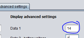
Keep in mind that this version does not use the value. It just calculates the value everytime you use 1A or more and makes it possible to display it as value "14".
value_14.PNG
On power on it will show the current resistance that you configured in the java configurator but during a ride when 1A or more is used it should show the calculated value.

I've attached the changes files. It should also improve the "resolution" for other displayable values like battery voltage etc. Use it at your own risk, only limited testing has been done. Will test it more tomorrow (if the weather allows for it).
 

Attachments

  • main.h
    15.7 KB · Views: 19
  • ebike_app.c
    125.4 KB · Views: 19
kallt_kaffe said:
...... It just calculates the value everytime.......
,......I've attached the changes files. It should also improve the "resolution" for other displayable values like battery voltage etc.........
:bigthumb: :bigthumb:
 
kallt_kaffe said:
I will actually have a go at modifying the firmware to calculate the internal resistance for me and display it. I have a pretty good idea on how to do it. I will of course share the code if I'm successful.
I may contribute in the future too, but I have not taken a look at the code yet. Therefore the question
How is the code maintained? Is this one here (legacy display adaptation) a feature branch?
Is code from the original development (main branch?) merged here?
Shouldn't your code be done on the main branch instead (since it is not display specific)?
Or are both projects non collaborating and diverging?
 
Well kallt_kaffe I see you are having fun, I'm on a summer break ...
Warning, multiplying ui16_display_data_factor x 10, it overflows. The operations should be 32 bit, but the higher resolution is lost in the calculation performed by the display to show the speed, it has a much lower resolution and it is not even linear, you can verify it by sending integer values ​​from 3.0 to 99.0 to the display.

A curiosity for everyone, the accuracy of the data displayed, can be improved by changing the diameter of the wheel.
With XH18 it works and perhaps also with the other displays.
The data values ​​sent by the controller are calculated according to the diameter of the wheel in inches set on the display.
I think the display does not use the diameter in inches for calculating the speed, but probably the circumference values ​​that do not exactly match the diameter. The consequence is that by changing the diameter on the display, the displayed value changes. Just look for the one that ensures the best accuracy.
I give an example, I displaying "Cadence sensor high percentage" which before calibration is 500 (50.0), if set 28 "I read 51.3, if instead I set 30" I read 50.3, much closer to the real value.
For a better resolution of the displayed data, for the same value, choose the larger diameter.
Remember that setting the diameter of the wheel on the display does not affect the displayed speed.
 
mbrusa said:
Well kallt_kaffe I see you are having fun, I'm on a summer break ...
:) Yes this is fun. There's a lot to learn still but I try to figure out stuff as I go.
Warning, multiplying ui16_display_data_factor x 10, it overflows.
Are you sure about that? That was my first concern so I hade a look at the code and it's populated like this:
ui16_display_data_factor = OEM_WHEEL_FACTOR * ui8_oem_wheel_diameter;

The largest wheel diameter I can configure is 35 inch and when I do ui8_oem_wheel_diameter returns 35. The highest OEM_WHEEL_FACTOR (in my version of the code) is 1435 so the highest ui16_display_data_factor can reach is 1435*35=50225 and that should fit in an usigned 16-bit integer.

The operations should be 32 bit, but the higher resolution is lost in the calculation performed by the display to show the speed, it has a much lower resolution and it is not even linear, you can verify it by sending integer values ​​from 3.0 to 99.0 to the display.
Yes, I noticed I can get it to display 195, 196 and 197 but I cannot get it to display 900 (becomes 910) or 350 (becomes 352). Still the resolution is slighty better for me when I multplied the ui16_display_data_factor by 10. Before I could display 195 and 197 but not 196.

A curiosity for everyone, the accuracy of the data displayed, can be improved by changing the diameter of the wheel.
With XH18 it works and perhaps also with the other displays.
The data values ​​sent by the controller are calculated according to the diameter of the wheel in inches set on the display.
I think the display does not use the diameter in inches for calculating the speed, but probably the circumference values ​​that do not exactly match the diameter. The consequence is that by changing the diameter on the display, the displayed value changes. Just look for the one that ensures the best accuracy.
I give an example, I displaying "Cadence sensor high percentage" which before calibration is 500 (50.0), if set 28 "I read 51.3, if instead I set 30" I read 50.3, much closer to the real value.
For a better resolution of the displayed data, for the same value, choose the larger diameter.
Remember that setting the diameter of the wheel on the display does not affect the displayed speed.
Yes I figured this aswell after looking at the code and changed my wheel diameter to 35 on the display.
 
Patoruzusos said:
I may contribute in the future too, but I have not taken a look at the code yet. Therefore the question
How is the code maintained? Is this one here (legacy display adaptation) a feature branch?
Is code from the original development (main branch?) merged here?
Shouldn't your code be done on the main branch instead (since it is not display specific)?
Or are both projects non collaborating and diverging?
I believe this code is a fork of original development at some point of time and now they are just different projects (mbrusa can correct me if I'm wrong). My addition (when finished, still a work in progess) I can contribute with as a pull request (if I remember correctly, it's been A LOT of years since I uploaded something to github) and the maintainer (mbrusa) can choose to include it (or not).
 
kallt_kaffe said:
Will test it more tomorrow (if the weather allows for it).
I did a test ride this morning and nothing seems broken. My internal battery pack resistance seems to be around 170mΩ. It needs some work still if this should be autoadjusting as current drops quicker that voltage so everytime you stop pedaling the number increases but for measuring it works.
 
kallt_kaffe said:
Are you sure about that? That was my first concern so I hade a look at the code and it's populated like this:
ui16_display_data_factor = OEM_WHEEL_FACTOR * ui8_oem_wheel_diameter;

The largest wheel diameter I can configure is 35 inch and when I do ui8_oem_wheel_diameter returns 35. The highest OEM_WHEEL_FACTOR (in my version of the code) is 1435 so the highest ui16_display_data_factor can reach is 1435*35=50225 and that should fit in an usigned 16-bit integer.
oops ... accustomed to numbers with the sign.
 
mbrusa said:
......
For a better resolution of the displayed data, for the same value, choose the larger diameter.
Remember that setting the diameter of the wheel on the display does not affect the displayed speed.
kallt_kaffe said:
......
Yes I figured this aswell after looking at the code and changed my wheel diameter to 35 on the display.
Do I understand well that it is advisable to setup inside the configurator the wheelcircumfence as precise as possible and the wheeldiameter on displaysetting as high as possible (35 inch) for the best data reading?
 
Elinx said:
Do I understand well that it is advisable to setup inside the configurator the wheelcircumfence as precise as possible and the wheeldiameter on displaysetting as high as possible (35 inch) for the best data reading?
Correct, however don't expect a major difference (if any). The changes I suggested (and made) should make enough difference that changing the wheeldiameter shouldn't matter much (or at all). My changes increase the source values by a factor of 10 by multiplying one value with 10 instead of dividing the source value with 10.

Also there is a lot of integer divisions in the code that I suspect causes a lot of rounding errors that perhaps should be addressed?

To be honest it's been years since I last developed in C/C++ but if I think integer divisions works like this:

Float: 19/10 = 1.9 (which would be 2 if you rounded the answer)
Integer: 19/10 = 1

This is easy to fix by just doing it like this:
Integer: (19+5)/10 = 24 / 10 = 2

You always add half the value you are about to divide with.
Another example, 3 / 2 which is 1.5 that rounds to 2. With integer division the answer will be 1 but if we apply the same rules as above:
(3+2/2)/2 = (3+1)/2 = 4/2 = 2

Another example (350 / 100):
(350+100/2)/100 = (350+50)/100 = 400/100 = 4

And a final example (349/100):
(349+100/2)/100 = (349+50)/100 = 399/100 = 3
 
kallt_kaffe said:
......
Also there is a lot of integer divisions in the code that I suspect causes a lot of rounding errors that perhaps should be addressed?
......
You always add half the value you are about to divide with........
Thanks for your explination.
I see now what could be the problem with the calculations inside the software.

If I follow your reasoning then it would be better if this will be done for all calculations for a better data reading.
Especially if it concerns calculations that require earlier calculated values.
I assume that this also applies to other calculations, such as multiplication, addition and subtraction, but that need another rule of thumb.
 
Just wondering if the group would appreciate a page were people could upload what settings they use for the new java app as well as what kit they are running e.g. tsdz2 36v 250w or 48v 750w. I thought if you could do a screen grab of your settings it would help others who struggle of what settings to input. Then we could compare each others settings and recommend any changes if needed.
 
Elinx said:
Thanks for your explination.
I see now what could be the problem with the calculations inside the software.

If I follow your reasoning then it would be better if this will be done for all calculations for a better data reading.
Especially if it concerns calculations that require earlier calculated values.
I don't expect it to make a major difference but perhaps if a value is calculated in several steps and many steps have rounding errors then I guess the end result will suffer more. It's just something I noticed, probably not really a problem.

I assume that this also applies to other calculations, such as multiplication, addition and subtraction, but that need another rule of thumb.
No, this is only a problem when doing integer division.
 
Suggy said:
....the group would appreciate a page were people could upload what settings they use ....
I think this could inside this topic. But imho it only make sense if there are made motified choices why some settings are changed from default values and what the benefits are of it.
Mbrusa, for example, has done this for "Start-up assistance without pedaling"
 
Hello all,

After installing custom firmware, my tsdz2 became unresponsive.
My xh18 display has the battery empty sign flashing, however my battery is completely charged.

I tried re-flashing my saved original configuration and also tried the factory firmware I found online.
ST programmer gives no error whatsoever when flashing these firmwares.

All have the same result: motor not working and xh18 battery red indicator flashing;
here's a picture: https://photos.app.goo.gl/H4wsgs9voaw2cMMt6


Can anybody point me in the right directoin on how to get my motor, who was working perfectly before?
The wires from my st-link to the speed sensor connetcor are 20cm long, is that maybe to long?

Thanks a lot for your help!

UPDATE: Fixed the issue, Option tab was wrongly configured
 
It has been a while since I have been here. I have now done around 1300km using the OSF with VLCD 5 on my Cannondale Scalpel and overall it is very good. I bought a Cube Reaction Pro with Bosch motor for my wife recently but she prefers my bike :) .
With the firmware, power level 3 (emtb) does not seem to change ie same as level 2 if moving up and same as level 4 if moving down. Is there a fix for this so you have 4 different power levels ? I also have the SW102 display which I have not yet opened was hoping to be able to use it without cutting it open. Any good news for me ?
 
danielson said:
It has been a while since I have been here. I have now done around 1300km using the OSF with VLCD 5 on my Cannondale Scalpel and overall it is very good. I bought a Cube Reaction Pro with Bosch motor for my wife recently but she prefers my bike :) .
With the firmware, power level 3 (emtb) does not seem to change ie same as level 2 if moving up and same as level 4 if moving down. Is there a fix for this so you have 4 different power levels ? I also have the SW102 display which I have not yet opened was hoping to be able to use it without cutting it open. Any good news for me ?
You are running an old version of OSF, if you update to last version you can use all assist levels with emtb mode.
What version of the tsdz2 and bosch motors do you have? Can you describe the advantages and disadvantages of each motor.
As far as I know, isn't yet possible to update SW102 without opening it.
 
kallt_kaffe said:
I did a test ride this morning and nothing seems broken. My internal battery pack resistance seems to be around 170mΩ. It needs some work still if this should be autoadjusting as current drops quicker that voltage so everytime you stop pedaling the number increases but for measuring it works.
An update on the matter of the internal battery pack resistance. Calculating the internal resistance and showing it is very possible, however the value varies as there seems to be a delay in the voltage fluctation when current changes. I actually did some filtering to try to minimize this in order to keep this fully automatic but in the end I realized that the same delays making it hard to get stable value is the same delays that will make sure the battery bars do some flickering even if you get the internal resistance value correct.

So I decided to take another approach to it and instead of trying to measure voltage flucation under load I instead save the voltage everytime the currrent has been zero (no load) for 2 seconds and use that value and that value only for the battery bars. I no longer use the internal battery resistance value.

I did 45km ride today watching the battery bars drop from 6 to 3 bars and did not see a single batterybarflicker during the entire ride. There is a catch though. If you ride a long time with constant load the battery bars will not update. The way I use my bike this is not an issue but I guess it might be for some people?
 
zegmaarmanu said:
Can anybody point me in the right directoin on how to get my motor, who was working perfectly before?
The wires from my st-link to the speed sensor connetcor are 20cm long, is that maybe to long?

UPDATE: Fixed the issue, Option tab was wrongly configured

Can you elaborate on the option tab changes, I have a unit which has lost the torque sensor readings since programming ?
 
Well It was the “option” tab that resulted in the error for some reason.
When finally I loaded my originally saved options tab, together with the factory memory & data tab, it came back to life 😊

The original options tab that worked has a '28' fill in the third set of '00'; The one I used before didn't which seemed to make the motor unresponsive.
 
Back
Top