KTM 200 exc goes electric

I had a few crashes last time, one is a bit worrying:

xNsbfgy.jpg


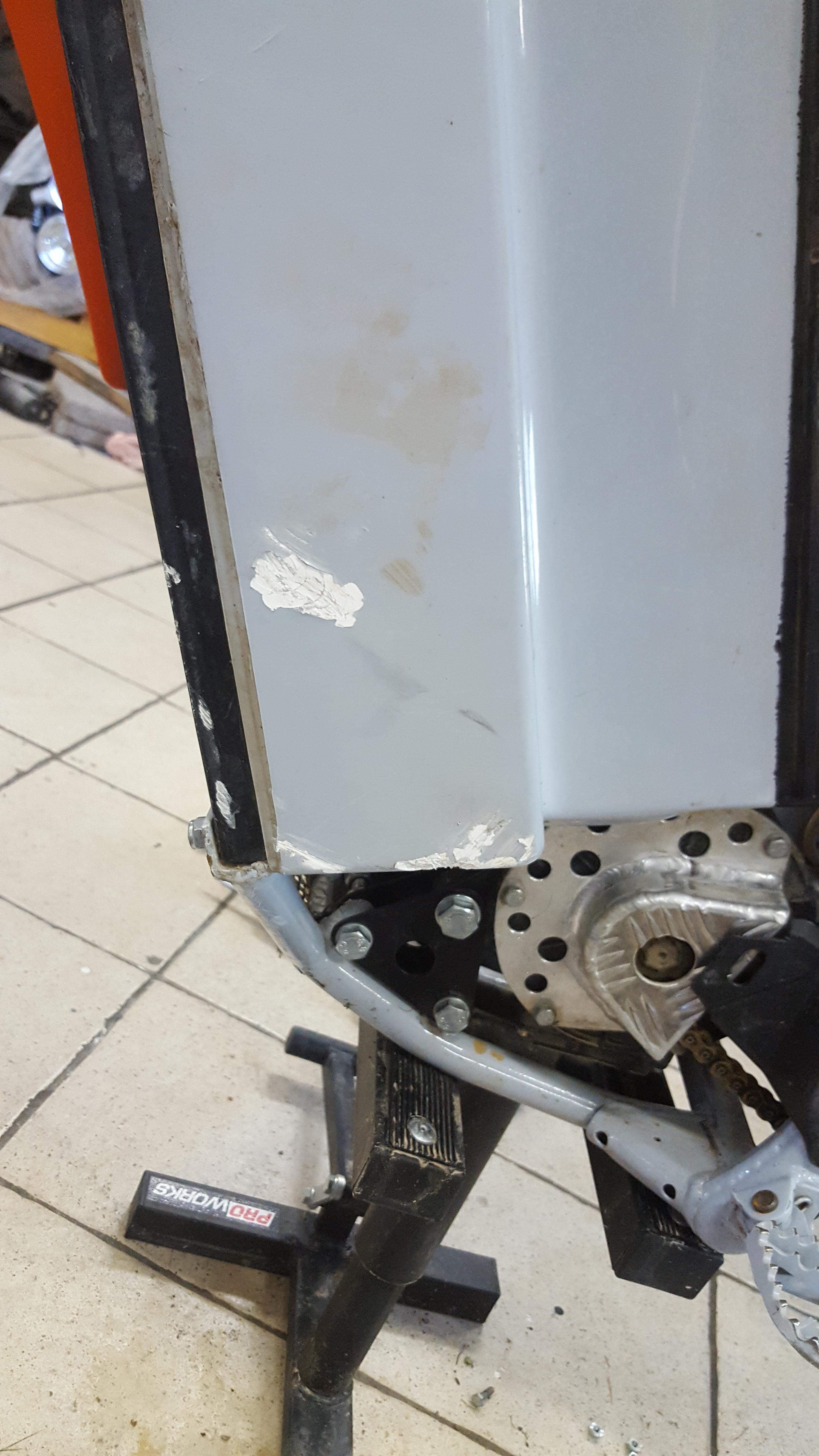
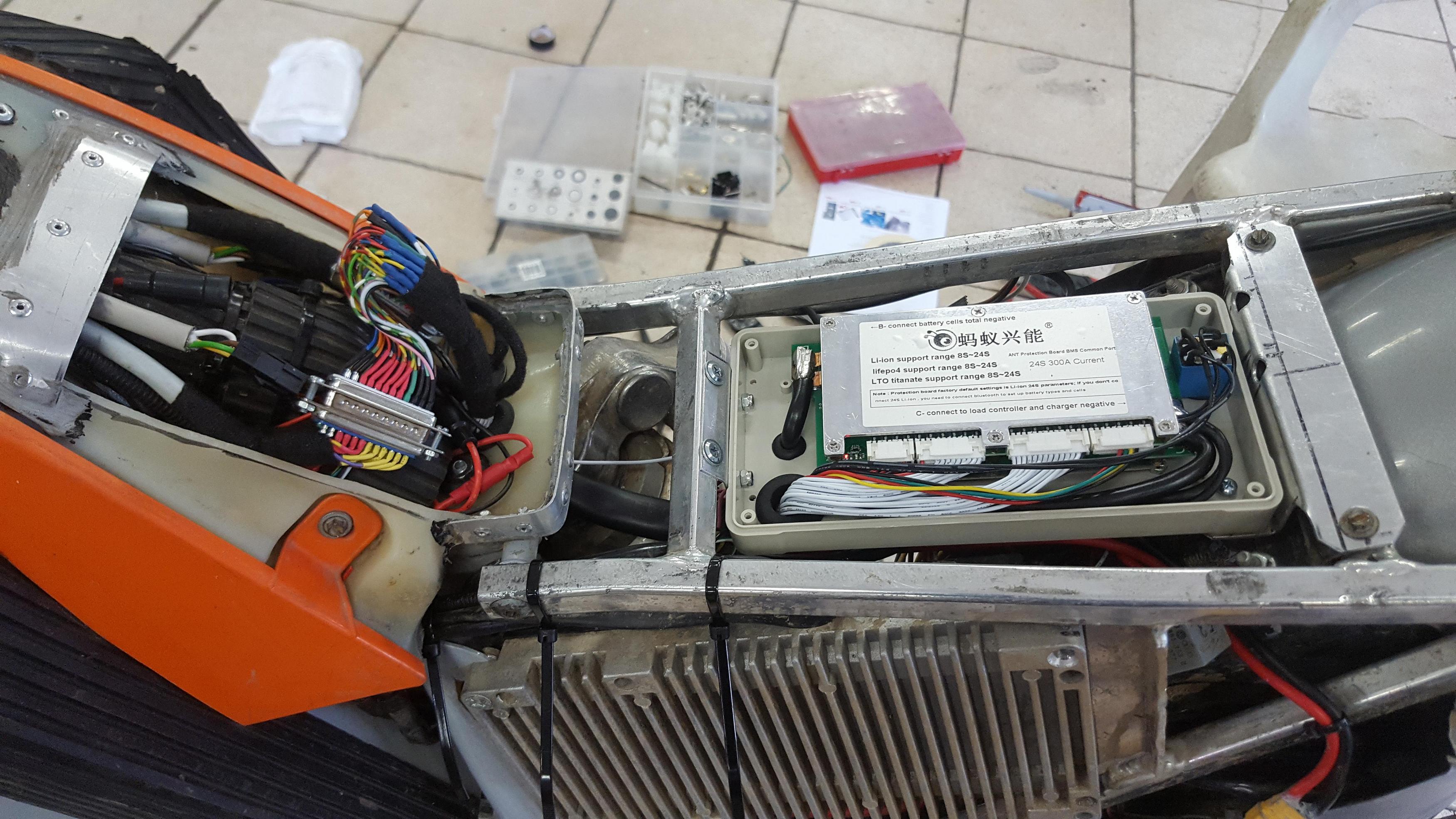
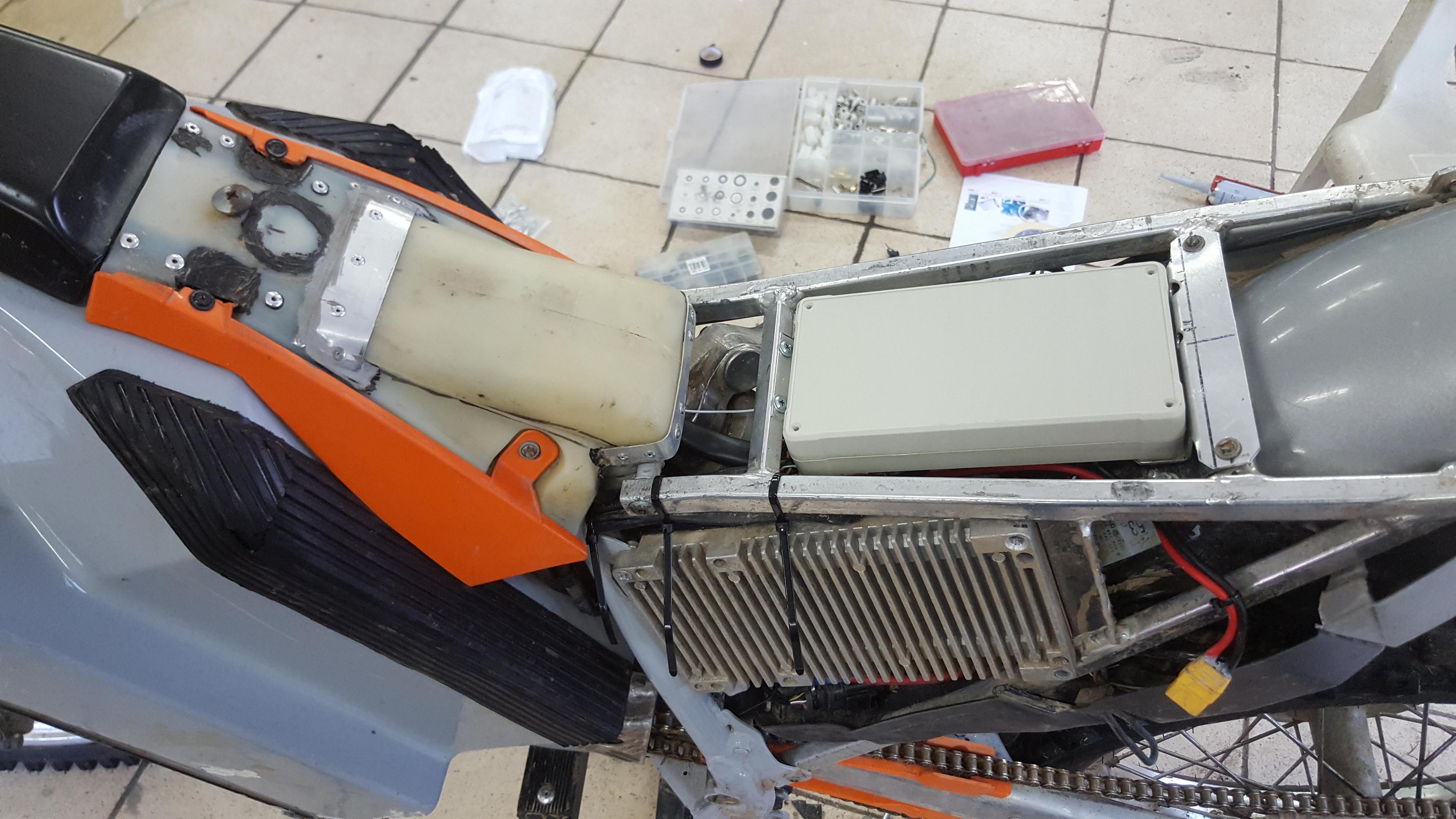
I hit a rock with the battery box.
It is a metal frame around the cells, but it is hard to tell how hard it was hit.
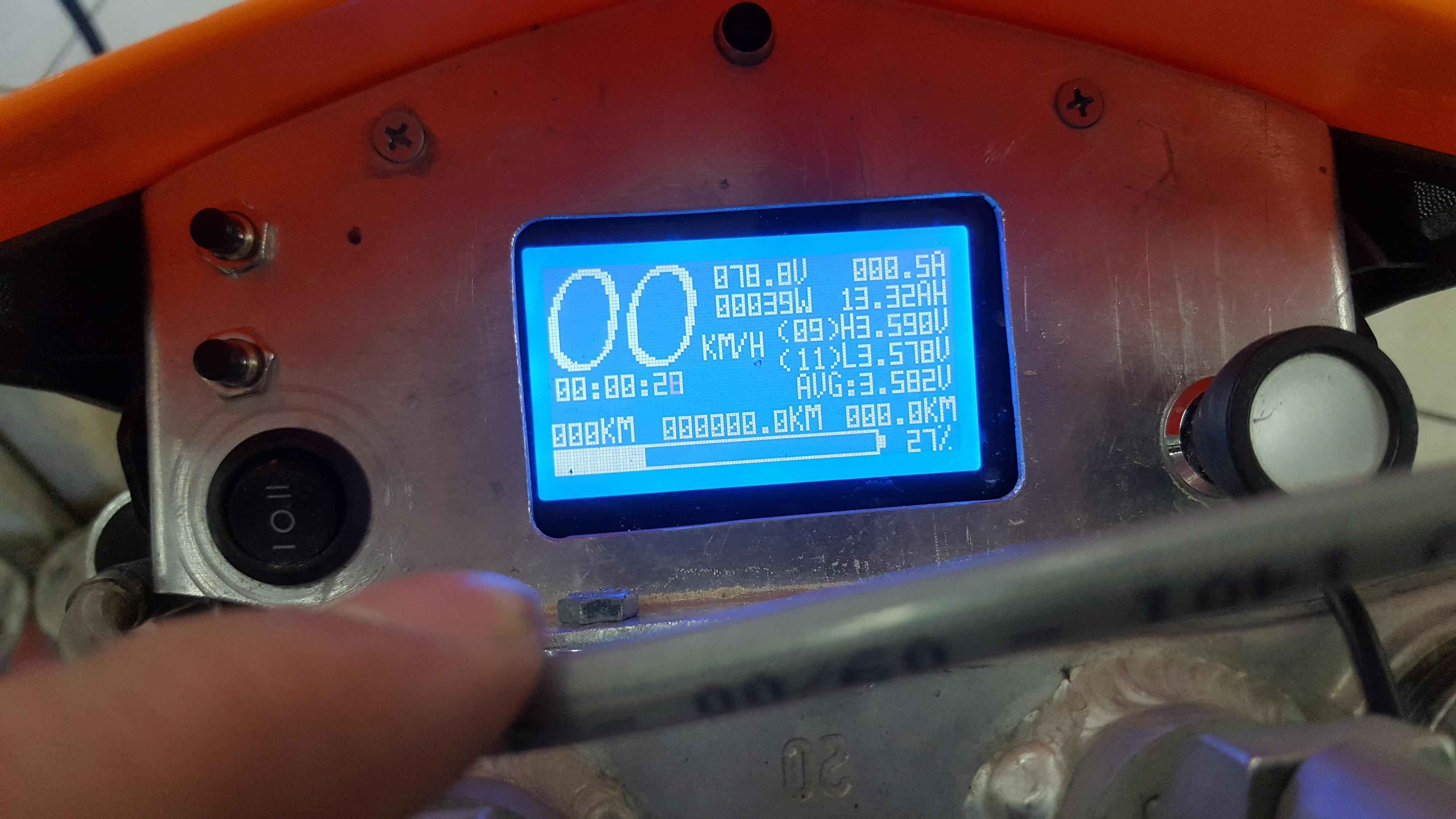
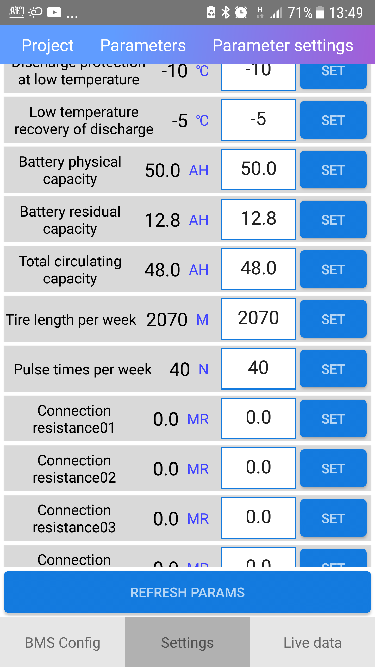
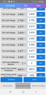
The fiberglass bounces back. The cell voltages seem ok, they are about 0.02 between highest and lowest.
That is about how well I balanced them, a few charges ago.

My shoulder took the hit from another crash, that seems to need some time to heal.
I think I have to learn not to crash :roll:
 
Time to get the bms in place:

6JGUbm2.jpg


I mounted it in the box, made brackets and wiring.

FBG5NbT.jpg


It is getting crowded everywhere..
But at least it is still possible to close the lids :wink:

eg6Eybh.jpg


In the previous picture you can see a small relay behind the bms in the box.
That is because I don't want an extra button to turn on the bms. Now when i turn on the ignition lock the contactors (and pre charge) turn on. Then when I turn the key to start position a few seconds the bms turn on.

The problem is that the bms don't seem to like that, I get pre charge error and it doesn't turn on the discharge mosfets.
I don't know if I can solve that somehow, or if I will have to mount an extra button to control the bms.
If I turn off the ignition (the contactors for + opens) I can manually turn on the mosfets with the app. Then I can turn on the ignition again, pre charge closes. Then the contactors, and everything works.
I didn't even know the bms needed a pre charge, I thought it handled everything itself.

yUhYnwp.jpg


The display. It is.. useful I guess.. But it actually looks better on the picture than it does in reality.
It is not very easy to read, where it is text it is in Chinese. But at least you can see cell voltages, total voltage and things like that. I will probably not try to look at it while riding anyway.

I have to turn it on manually with the upper button, and I don't like that. But it seems to work and turn on automatic if I keep the button pressed all the time. I will probably test to just connect the wires to that button together and see how it turns out.
The other button is for changing what the display shows.
 
Started working on the sprockets:

lXURkhF.jpg


9gDAqit.jpg


Got it pretty decent dialed in on the lathe.
It is not perfect, but not more than 0.2mm off so far..

8Ofm2Fj.jpg


80tooth 428 in the bottom, then 70tooth 428, 48tooth 520.

RrAYI81.jpg


My new 11tooth front sprocket. It is tight.. So tight I couldn't get it on all the way with light force.
I will pull it off again and clean up the axle better, then heat the sprocket a little.
It is a big difference from the Chinese ones :wink:

A9j18Fq.jpg


I made some sort of drill guide, time to do something about the weight..
It started about 4kg, when I was finished in the lathe it was a little over 3kg. (I just used a bathroom scale, so not very accurate)
I hope to be able to get it down to half or something..
 
j bjork said:
180 holes later:

I hope I didn't overdo it :shock:
It is pretty light anyway, under 1kg on the scale..
Lets hope it survives. That looks like radialy laced rim and we all know cross laced is stronger but I have no idea what will happen next :lol:
 
j bjork said:
180 holes later:
I hope I didn't overdo it :shock:
It is pretty light anyway, under 1kg on the scale..

I think you did it over due.
did it over
Cut to many holes for it to still be sane

I looks that it may be too weak when pushed the hardest

Det känns inte som att det där var lagom... (translated. "not even")
 
Well, tomorrow I will get it all mounted and try some launches.If it seems to hold up I will try it on the track on Sunday.
After all it is 7mm thick steel, so it is not super flimsy. A problem can be that I use pretty hard regen,so if it flexes it will be back and forth.In that case it will probably break with time.
A cross pattern would for sure be a lot stiffer. I considered that but it seemed harder to do, and heavier :roll:
If I do it again I will probably do something similar to the black sprocket in an earlier picture.
 
Great work so far :bigthumb:

Although I hope it is a steel chain wheel but it looks more like aluminium? For better strength you need diagonal support from the mounting holes to the outer teeth. So when (not if) it breaks make a new one like this (red parts cut away):


Kettingwiel.jpg
 
I would say on the next one make the cutouts like the black sprocket In the picture on top of that one. Pretty much all things mechanical need triangulation for strength. Just be careful with that while riding....if it folds under Acceleration or deceleration from regen, it’s liable to lock the rear wheel up.

Tom
 
But but but? You could’ve just taken the middle section of the sprocket down to 2-3mm or so on the lathe. Would’ve been strong enough and a 5min job.

I’m quite worried you went overboard with the sprocket lightening. try it out carefully before going full attack.
 
Yea, I didn't really realize until the holes were drilled..

As I said, it is 7mm steel. And if I did it again, I would do something similar to the black sprocket.
I did a short testride today. I planned to just test a few wot:s at low speed, and check that it looked alright.
The plan was to use my nice 11tooth front sprocket, but I was curios to see what difference 8:1 would do from 7:1.
I also got some 10tooth chienese I ordered this week, so I mounted one of those.

And damn, it sure made a difference :D
It power wheelies now, before it just lifted slightly at first. Now it keeps rising. So it seems like I will still go with 10tooth :?
I wanted to use the 11tooth to save the axle on the motor.. It would be absolutely no play, but with the 10 tooth there is a lot of it :roll:
I didn't want to crash with a locked rear wheel at high speed in shorts and t-shirt, but I couldn't help myself from more wot:s then I had planned..
Anyway, afterwards I could not see any problem at all with the sprocket. But it is not the same as landing at speed, loosing and suddenly get traction and things like that.

xT6OezN.jpg


YsFnej7.jpg


Hmm, I wonder if I could do 90, or at least 85tooth?

bLdBnei.jpg


I had to cut off half the the weld for the inner bracket for the chain guide.
I think it still is strong enough. I have a little margin now, and I can take a little more before I think it is too weak. 85tooth would probably be possible, but I think I would have to weld a new bracket if I go 90tooth.
 
Back from today's riding. It wasn't that much today, about 20km of mostly dry dirt and rocks.

g0Y5rlL.jpg


Sprocket and chain seems to held up fine so far.
It is a D.I.D x-ring chain this time, expensive but hopefully it will last..

This damn button was problematic though:

AVbTCQf.jpg


My new regen button. The old one died in the mud last ride.
This one should be "waterproof".The problem was not the button, but that the bracket would not stay in place.
I put double sided tape between it and the handlebars, but apparently it wasn't enough. The 2 ugly screws are an attempt for a quick fix, but it wasn't enough.

I hate to say it, but it is almost too aggressive on the throttle now :wink:
I could tame the controller, but I don't really want to..
The problem is mostly that there are a "kick" somewhere about half throttle. When you hit that spot it will spin, especially in a bend or on bedrock or something like that. I was getting more used to it after a while, but I think I should measure the throttle and see how linear it is.
 
I built a test rig of two of the leftover cells from my battery:

94hjDNv.jpg


Then I did some charge and discharge tests.
The first charge test was after they haven't been used for a year at least I think:

10A charge.jpg

A 10A charge (25A cells)

5A discharge.jpg

And a 5A discharge.

25A charge.jpg

Then I tried a 25A charge, or 1C. There seems to be a small heating of the cells, like 2 degrees C or so.
I think it seems ok to use once in a while? I have 22s2p, so that means 50A charging. It is what my bms and charger can handle :wink:

40A discharge.jpg

Then I tried 40A discharge, that is what my charger can handle. It would have been interesting to be able to do a pulsed 150A discharge, but I cant.
I had a little bit of heating, but not the same on both cells. One seemed to not heat at all almost, while the other seemed to heat up about 7 degrees. I just measured with an ir thermometer and my fingers, so not too accurate.

With this I am trying to figure out how high to charge and what LVC to set. It is pretty obvious that there is not much left under 3,5V, but then there are voltage sag..I don't want to start limiting and cut off too early, but it would be nice to have a meter that shows how much there are left on resting voltage.

I think I have seen settings for 20%, maybe 40% etc. in the bms. But now when I look this is the only values I see that can be something like that:

n6wokCe.png


Now I have 81,1v and it shows 52%. I'm not making much sense of this :?
Edit, I posted the wrong graph at first, corrected now. But an extra graph seems to stay at the bottom of the post for some reason.
 

Attachments

  • 10A charge.jpg
    10A charge.jpg
    38.4 KB · Views: 2,936
Thanks, the biggest problem seems to be how to set up the bms now..

The only more obvious values to set up seems to be "battery physical capacity" where I set 50Ah for 2p of 25Ah cells.
The next value is "battery residual capacity" If I lower this value,the battery % goes down. The problem is, if I just wait a little it goes up again.
Then there are "total circulating capacity" I guess it is how much Ah can be used between end of charge and end of discharge (or maybe hvc and lvc?) Changing this doesn't seem to have an effect on the battery %
 
I installed "vbms" instead of "my bms" (ant).
It seems like I cant have both at the same time :?
I was a bit surprised to find that it looked almost exactly the same.

The status screen has the same confusing layout where the cell group numbers doesn't add up, temp and other things is also called a cell nr and things like that. But the settings were a bit cleaned up. The same settings dosent come again, not so much confusing set up a resistance in volt or mA and things like that.
But now it seems there are no other possibilities to set up the battery % than the ones I have played with.
A strange thing happened though, I just confirmed my setting in "battery residual capacity"and it went from 51%to 26% like the other times I tried. This time I gave a little throttle afterwards, and now it has stayed at 26%
Edit, it was temporary. Now I am back at 51% :(
 
That version of My BMS looked really messed up. Looks like the description of the parameters has been moved around or something. Wished I could remember where I got the version on my phone from, but it had been working quite nice.

Do you have 3 parameters after each other with AH like in the picture I attached? Battery physical capacity is the useable capacity that the counter resets to everytime I fully charge the battery. Battery remaining capacity is battery physical capacity minus used capacity. This is what the percentage remaining capacity is calculated from. Total cycle capacity is just a total counter for how many AH has been used from I started the board.

The app and the board has been good, and the percentage is quite close to spot on, even after several partial charges. I will dig some more and see if I can find the version I have if you are interested.
 

Attachments

  • Screenshot_20200724-213354_MaYi-BMS.jpg
    Screenshot_20200724-213354_MaYi-BMS.jpg
    116.4 KB · Views: 2,857
Thanks, yes I have the same settings:

NJUIyt1.png


It makes sense what you say, the last value"total circulating capacity" dosent seem to make a difference.
The middle value "battery residual capacity" seems to work to change, but only for a while.
So I guess I should just leave them alone, and stop messing with them?
Then set up the first value "battery physical capacity" with the available capacity from my hvc to lvc, or a little before lvc where it falls off dramatically.
I think I should set lvc a little low, so I don't hit limiting and lvc to soon because of battery sag.
 
Yes, I think you should leave "battery residual capacity" alone, just charge the battery and set it to the same value as "battery physical capacity".

There might be one more setting that can apply to this if it keeps jumping around. I noticed a setting "SOC Auto calibration method" below the "xx% cell voltage" settings. It has always been set to "2" in my BMS. I havent played withnit, but I would guess it has something to do with how the percentage left is calibrated. Mine doesnt seem to be affected by whatever I set the "xx% cell voltage", it only resets the capacity when it reaches 100% cell voltage and counts amp hours from there. Maybe if this "SOC calibration method" parameter is set to something else it takes the cell voltage into consideration, and that is why yours is jumping?

As long as the controller lcv is higher than the bms lcv it should take care of it. My BMS is a couple volts lower than the controller, and you notice the power reduction way before the BMS cuts. Mine cuts from the cell diff voltage if I drain them too deep. LEV40 cells from an Outlander that is perfectly balanced until they take a deep dive right at the end, then they suddenly differs more than 0.3V...
 

Attachments

  • Screenshot_20200725-201716_MaYi-BMS.jpg
    Screenshot_20200725-201716_MaYi-BMS.jpg
    115.6 KB · Views: 2,819
I would recommend using the JT 11t front sprocket that you have.
After 1 year of using those cheap Chinese sprockets, my motor shaft was nearly stripped.
I machined the shaft slightly so the sprocket slides on further.
Heated the JT and tapped it into position. Wasn’t excessive force required.
Feels so much better now.
 
Stevebequik said:
I would recommend using the JT 11t front sprocket that you have.
After 1 year of using those cheap Chinese sprockets, my motor shaft was nearly stripped.
I machined the shaft slightly so the sprocket slides on further.
Heated the JT and tapped it into position. Wasn’t excessive force required.
Feels so much better now.

Yes, it worries me too to keep using the Chinese 10 tooth. I am trying to figure out what gearing to use, and how big rear sprocket I can live with.. Going from 7:1 to 8:1 sure did a lot of difference. It is a lot snappier and stronger at lower speed now. On the road it is obvious that I lost some "punch" at higher speed, on the tracks I have ridden so far I don't think it has been very noticeable. But maybe on faster tracks.
I am considering going 11 front and 85 rear, for a total of 7,73:1. 80 tooth rear is already big, I hope 85 will be ok..
 
Back
Top