I'm looking for developers/engineers interested in high current (+1kA) controller development

zombiess

10 MW
Joined
Jan 31, 2011
Messages
3,048
Location
Oklahoma City
I've been working to develop a high current controller for several years. The journey has involved crazy amount of research to figure out viable solutions for working into the +1kA range in a compact design using multiple paralleled commodity devices. While I have worked on this project on and off over several years, one thing has kept me from making the progress I really need to make, working with a team of others who are also motivated to push the limits.

There are a bunch of challenges involved, many which it appears I've already overcome, but I've come to the conclusion that I'm not able to go at this solo as I have been trying to for so many years. One of the larger challenges is controller development. I really desire to run a custom controller built around TI's Instaspin FOC. Instaspin has a steep learning curve (shaped like a cliff) just to handle simple tasks like getting a throttle setup and having the code execute upon boot, however I've made it past most of these hurdles, and have several dents in the walls shaped like my head in various locations throughout my office from getting stuck. The reason for developing with Instaspin is due to needing some customized control to accommodate some of the ideas I've come up with. Right now I'm working to get a VESC based controller working and have the hardware designed. Making this hardware compatible with Instaspin is fairly straight forward as I made my controller modular. I'm hoping VESC is simple a stop gap on the way to more advanced ideas.

I have built a full scale half bridge using 9 paralleled TO-247 devices and through double pulse testing have verified near equal current sharing among all devices. Since that design several years ago, I've managed to shrink it to a much smaller scale and improve upon it as well as increase the MOSFET count up to 24 TO-220 devices.

If you have a background in any of the following and are a highly self motivated individual:
programming C
motor controller design / algorithms
power electronics
production / manufacturing
business contacts
machining (I need custom aluminum and possibly copper parts made)
if you think you have skills which you could contribute I'd be interested in hearing from you.

I don't exactly know where I'm taking this project, I would like to turn it into a commercial product as there is very little available for high current 3phase controllers. At this time the design is closed source as it needs additional proving, but I'm tempted to open it up after some further development.

If you would like some references about my design, there are a few on this board who know about my work. They should be able to vouch for the validity of the concepts used in my design. I realize extraordinary claims require extraordinary evidence and I can prove my concept is viable through different test apparatuses I have built.

If you don't know who I am, please search my posts, especially those involving controller design to get an idea of my skills and personality. I like to push limits, but without breaking rules (maybe bending them). Feel free to contact me by PM. I'm looking to form a small group to make this happen, and hopefully have a lot of fun geeking out.

Link to one of my recent designs, unrelated to the high current design mentioned here.
https://endless-sphere.com/forums/viewtopic.php?f=30&t=106688
 
I'm curious to know what are the issues with the VESC software stack? Why not just improving it to fit your needs? Wouldn't it be easier to build on top of an existing platform ? I haven't looked yet at the very deep details of VESC firmware, but I guess some part of the code could be reused for a TI MCU running instaspin. There is also this ChibiOS thing running is the VESC that might not be compatible with TI MCU or instaspin code. I don't know...

Developping a complete new firmware + software stack for a new MCU is a huge task. The software dev effort might be tenfold the hardware dev...

I could probably help for such a project thought if I get some more details on why the VESC software is not appropriate for the task.
 
I started something like this in 2016 but stopped for 2 reasons. First one was that it was a project to work on while I was unemployed, once I found a new job it got benched. And then I never restarted because, well, I have no use for a 1kA motor controller and was more interested in Sensorless From Standstill (which I then developed during my stint of unemployment in 2018 :? I am not a nice employee, I can build what you want but am not interested in management scheduling nonsense... )

I had some interesting ideas though, completely different from yours. I will just describe what I did and what the idea behind it was.

As you may know, I am not a fan of parallelling lots of FETs, I am more into parallelling complete 6 FET stages / controllers.

The main idea was to parallel a whole bunch of 'slave' controllers (each with a 6 FET stage) all controlled by a master controller. The slaves had synchronised PWM stages (all in sync with the master) to be able to parallel them. Each slave controller had its own current sensors. With these it could observe how much current it was providing to the output, relative to all the other slave controllers. Then the slave could influence its own contribution by increasing or decreasing its own deadtime. I wanted actively controlled current sharing for guaranteed reliability, and not be dependent on equal length wiring, matched FETs or any of that (nonsen... eh uncertain type stuff that also changes over age, heating, supply voltages etc etc).

I got quite far:

- the master controlled all the slaves over I2C. The master could discover on its own how many slaves there were, and assign each its own unique I2C address. Then it could give individual commands to each slave, and also read out all status registers of each slave. The setup of the controller was only in the master, on startup it distributed all settings to all the slaves. In this way there was maximum flexibility... you could for instance take out a slave or add a few and it would still work. I set it up for 64 slaves (and when you're at 150A for a 6 FET slave with 4468's....)

- the master generated a synchronisation signal for the PWM stages. It was quite easy and straightforward to get all PWM stages in sync to within 50 nsec (each slave had a PLL like structure in the code to sync with a master generated signal). If you then have 500nsec deadtime you are guaranteed no shoot-through. And then for current adjustment a slave could increase its own deadtime to reduce its own current contribution. Increasing deadtime will still prevent you from having shootthrough.

- slaves could disable themselves when they went out of sync for some reason. A slave could also shut down the entire controller.

- each slave had a set of 3 current sensors. With simple 1 kOhm resistors these were all connected to 3 star points which fed into the master controller. Each slave had 3 analog inputs for its own current sensors, and 3 analog inputs for the star points. Because of the analog averaging on the star point, the slave had information about the overall average current flowing. And because it had the info from its own sensors, it could compare between the two to regulate its contribution (via the aforementioned method of using the deadtime).

- The PWM output stage of the master was used to generate PWM signals that, together with opto-couplers, made sure the output was doing what it was supposed to (like these fancy 333 gate drivers that auto-shutdown, I cannot think of the term now). So when an output was high when it was sopposed to be low, it would shut down immediately. The wait time between output supposed to change and output must be changed was digitally settable, it was not analog based on RC times.

I got to the point where all the PWM outputs were running in parallel and synchronised, and it could detect a short in an output (so it could see and shut down when an output was not doing what it was supposed to). Did not have the current sensors added yet or any sort of motor control algorithm (but that was the easy part). Did not get to try out the idea of influencing the current sharing by using deadtime. I used 33EV chip, which ran at 70 MIPS and had a 7 nsec grid for the deadtime...

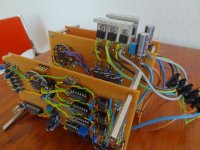
DSC02309.jpg
the master in the front, with two slaves behind it

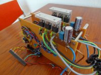
DSC02310.jpg
I used a sort of ribbon-cable bus to connect master and slaves together, at a later point might have considered optical connections (like with the plastic light-guides that you see in audio)
 
I've tried this on a couple of projects before, and it hasn't ever gotten very far (both my fault and others), but I'm interested in helping however I can. I'm useless for the electrical design, but am an ME by degree and own a CNC shop. I've started a team building a land speed record motorcycle for 2021 and maybe this could go hand-in-hand? Shoot me a message if you'd like.
 
Lebowski, that is a really unique approach. It's like eating an elephant, it's done one bite at a time.

I looked into a somewhat related approach using multiple gate drivers, however I did not like the variation in timing and dependence on software. I never built anything using this technique as I eventually figured out a way to let physics do all the work for me naturally without any software intervention. Now I just need to finish building it. I have found someone who is assisting me with a unique current sensor design so the controller maintains good low current resolution along with high current. I'm currently in process of acquiring a test vehicle to install this controller on. It's a big undertaking, but things look like they are starting to come together.

How do your scope shots look on your gate drive during pulse tests with the through hole parts used? Did you know you can have prototype PCBs made for a low cost and move to SMD parts with ease, even the assembly? I use to dislike SMD and was a through hole part guy, now I prefer it.

ENNOID, I am using VESC for now because it's been through several revisions and has been pretty well proven so far (Axiom is +100kW on it). I suspect that I'm going to surpass the limits of the STM32F405 uC as it's already maxed out when running 60kHz PWM, which should be enough, but I might be dealing with some custom very low inductance motors. These issues will be addressed when needed and until that point, VESC appears to work well. Not having a controller I can modify myself for my power stages has been a big holdup. I've gone down the TI Instaspin road a few years ago and got it working on my own hardware, but as you say, taking on development is a huge task and there is no way I can handle everything needed by myself. I then shelved controller design for a few years until I started seeing more VESC based projects pop up. That fired me up again.
 
Any TI MCU in mind? Ideally something automotive grade I guess?

What is the status of your firmware development? Contact me in PM if you are ok with sharing some infos about your project.
I want to develop my own lineup of inverter one day compatible with my BMS system and offer them for sale on my website, this could be an opportunity for me as well. I cannot do it all by myself...

Axiom is overkill for most applications and VESC 4.12 or 6 are now almost a commodity, there is a sweet spot in between, that spot is currently occupied by Sevcon & curtis controllers.

There is the new trampa 100/250 and 75/300 vesc getting close to this, but there is still room for newcomers
 
ENNOID said:
Axiom is overkill for most applications and there is a sweet spot in between, that spot is currently occupied by Sevcon & curtis controllers.

I fully agree with that statement. I really like the Axiom VESA-based design but I don't need to drive that large of a motor. A modified design that could handle up to a battery voltage of 180-200v at a current of 400-500amps for the 35-60 kW sized unit.

So for now I'm choosing the Kelly KLS14401-8080IPS controller for the kart project because it is best fit size, weight, and price wise (without going down the verboten Sevcon software rabbit hole), although I'd like to customize it a lot more with multiple drive modes and throttle maps - much like I can do with my road-car ECU.
 
What market do you see for +1kA inverters? I am not sure the copper cost to conduct such high current is justified by the benefits of lower voltage batteries. For higher voltages, like the normal ~350V, you are looking at 350kW which is quite a bit of power.

There is also the problem of how to conduct all this current. It's going to take very large wire or multiple large wires. 150mm^2 total at a minimum. There are very few if any options for 1kA rated connectors, and those connectors will require MUCH larger wire to meet the rated ampacity.

I still think it's a cool project and could definitely see it being useful for some high performance applications. My interests lie more with high power density inverters, but I might be interested in helping with this project.
 
zombiess said:
I suspect that I'm going to surpass the limits of the STM32F405 uC as it's already maxed out when running 60kHz PWM, which should be enough, but I might be dealing with some custom very low inductance motors.

ST makes it relatively easy to migrate code between families, or so I've been told by my software engineer coworkers. We designed the STM32F412 into a new product (not a motor controller) and it's a solid microcontroller. The F4 series has very good features and performance for the price.

The new STM32G4 series looks promising with their analog peripherals, but they have less flash and RAM (512/128Kb) than the F4 series. How much flash/RAM does the VESC software use on the STM32F405 (1024/192Kb)?

The STM32F7 series is the next level up, but that's a bigger change going to an M7 core.
 
ENNOID said:
I haven't looked yet at the very deep details of VESC firmware, but I guess some part of the code could be reused for a TI MCU running instaspin. There is also this ChibiOS thing running is the VESC that might not be compatible with TI MCU or instaspin code. I don't know...

Developping a complete new firmware + software stack for a new MCU is a huge task. The software dev effort might be tenfold the hardware dev...

I was surprised to read that VESC is running an RTOS. I would have thought that a dedicated control loop would be more appropriate for motor control, but then again VESC does a lot of other things that are easier to implement using an RTOS. Personally, I would want to strip out the USB but keep the CAN which is much more robust. Does the VESC PC software require the USB interface?

The software will definitely require more effort than the hardware since it sounds like the hardware has a big head start, which is all the more reason to stay in the ST MCU family if possible.
 
bww129 said:
The new STM32G4 series looks promising with their analog peripherals, but they have less flash and RAM (512/128Kb) than the F4 series. How much flash/RAM does the VESC software use on the STM32F405 (1024/192Kb)?

The STM32F7 series is the next level up, but that's a bigger change going to an M7 core.

The errata sheet of the g4 series is some kind of joke. I just wouldn't.

H7? H7 is nice. I have a h7 for another project and it's virtually limitless in cpu power for any motor application.
 
Hadn't seen the errata for the G4 series but there is quite a laundry list of items in there! Good thing the ST rep didn't persuade us to go that route! It may be worth waiting to use it after the next couple silicon revisions...

The H7 would be a good option too. All the higher end micros start out with the larger 100-LQFP package. You could go with the smaller BGA package at the expense of board/assembly complexity, which may not be the best choice for this type of application.

The Infineon XMC1000/4000 series is also a decent platform for motor control. The XMC4000 is more of a competitor with the STM32F4. The XMC1400 is a nice option for cost conscious motor control with on-board CAN.
 
This sure is interesting, as others have pointed out there are not many options at higher currents and lower voltages.
There are motors, but it seems there are almost no controllers except for sevcon.
I think lebowskys way is partly interesting. It sounds to me that a bunch of 6 fet controllers would be bulky, but personally I would really like 2x500A controllers on the same motor.
On a dirt bike like I am building, it is hard to fit one big controller. But 2 smaller, where the radiators was would be perfect.
 
Back
Top