
kdog
10 kW
Hey garolittle
Whats the conductivity? IACS?
Cost? And where did you get it.
Cheers for info.
Whats the conductivity? IACS?
Cost? And where did you get it.
Cheers for info.
kdog said:Hey garolittle
Whats the conductivity? IACS?
Cost? And where did you get it.
Cheers for info.
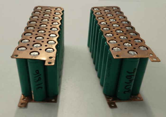
spinningmagnets said:Merlin, have you tried the copper/nickel sandwich method. I highly recommend it for series connections.
0.20mm thick copper on the cells, and 0.15mm nickel over it. The nickel provides the resistance, and that size copper can easily handle 30A peaks, possibly more.
Copper is four times more conductive than nickel, so 0.20mm copper is equal to 0.80mm nickel...plus less heat.
 )
)
hallkbrdz said:Or... this approach looks very robust and easily made to carry the 350A surge current I'm designing for (borrowed from spiningmagnet's ebike site
Spot weld the strips to the buss bar, then attach the strips to the cells.
hallkbrdz said:BTW - Keith said the KWeld kits won't be back in stock until the end of September. No details as to why.

spinningmagnets said:Discussion that is specific to the copper/nickel sandwich" method will now be moved to here:
"Copper/nickel sandwich" buses for series connections
https://endless-sphere.com/forums/viewtopic.php?f=14&t=108006
Do not go over 12v, start with 2 packs in parallel, those are 120A max cells, so you end up with 960A capable pack. Limitation will be the nickel connectors.Tommy L said:I
Kweld manual says 4-30V input 2,000 amp max so I'm thinking of putting two of my 12.8v nominal A123 9.6ah packs in series for 8s or 25.6V Nominal with still a CCA of 250 or 400. I might need to also run some more in Parallel too.
Any insight on using LiFePO4 on Kwelder????
parabellum said:Do not go over 12v, start with 2 packs in parallel, those are 120A max cells, so you end up with 960A capable pack. Limitation will be the nickel connectors.
P. S. If those are cut 36v medical packs, filter out the block with the fuse weakened tab.


