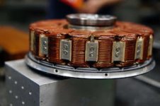
APL's DIY axial-flux motor

fechter said:
The best material I can think of would be titanium, but that's probably too expensive. Titanium is a very poor conductor so would minimize losses compared to aluminum. Any kind of metal is going to need a slot to break the loop around the cores. 300 series stainless steel (non-magnetic) would also not be too bad and much cheaper than titanium. I don't know how conductive carbon fiber would be in this kind of application but would also probably work well.

I'm pretty surprised the fiberglass was too flexible, but one of those things you find out from testing.

Anyway, a huge accomplishment to get it on the bike and actually ride it. Sounds like it will be awesome if you can get past the flexing issue.


Ti may be cheaper than you think. I have a supplier for surplus plate that may have something suitable.

APL, come up with a model and shoot it over and we can go from there. You pay for material and I'll do the machining for free if you can't do it, or I can source the plate for you.
 
Wow colesasterling, that's a real game changer, and a gracious offer! I've never been able to find any titanium, so
pretty much ruled it out. I'll draw up a rendering, and we'll see where it goes. Maybe this can work, and save this
build. :thumb:

I'm beginning to think that it's a design flaw, more than a materials flaw though. trying to hold the cores from moving,
"from the axle", is probably the lesson to be learned here. At least from a plate. Recon were going to find out.
(Putting 18 slots in it could be the problem too)

The Emrax motor uses saddles on a wide base to hold the cores, but it's also a smaller diameter, which is another part
of our problem,.. the almost 10" diameter I have. Other axial's use an outer cage to grab the cores from both the center
and outer sides at the same time. But that leads to complexity, and an in-runner design.

Emrax motor copy.jpg

Thanks for your suggestions stan.distortion, I thought about making my own custom carrier out of boat cloth and resin,
using a multi direction lay up, and built-in ribs or contours. I'm hoping that one of these other materials will work first.
Your idea of potting the whole thing is good as well, and would probably work, but it would be the last resort, because
it would be one solid mass at that point, so I'll save it for the doomsday option.

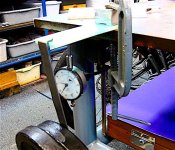
What I need to do is make a materials tester to see what the different flex strength's are between fiberglas, carbon,
and aluminum,etc. A simple clamp and weight, with a dial indicator should do it. Make the test pieces the same size,
and hang the same weight, then check the amount of bend with the indicator.
It would be nice to know what the real world differences are.

Other than the titanium,(and hopefully that will work), I'm inclined to try the carbon fiber plate. It's available, cheap,
and easily machined. Which makes it DIY friendly, It needs a flex test though.
 
I did a little reading up on these materials, and from what I can gather, it really depends on exactly what the make
up of the material is. There are lots of different kinds of carbon fiber, as well as aluminum and Ti. Depending on the
quality, some strengths can overlap. A cheap version of a stronger material can be worse than a good version of a
weaker material.

Looks like titanium has them all beat though, although there are different grades of that too.

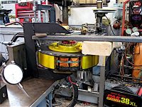
I did some flex tests on the fiberglass that I'm using, and some 6061 aluminum. Cutting some roughly 2" x 7" strips
and clamping them to a steel table, I hung about 20 lbs on it and measured the difference.

The aluminum moved .020" on the gauge as compared to .056" for the fiberglass,.. so almost three time as strong,
flex-wise.

Fiberglass flex test..jpg

The next step is to try to determine exactly what is moving when it rubs. I assume that it's the stator carrier, but if
I'm wrong, then there will be a lot of work for nothing. So I better make damn sure.

I tried propping up the rear wheel and running it with the rear brake on, to get a visual, but it takes an awful lot of
power to get it to do it's thing, and a bit scary getting my head near that monster, so I'm going to think about this. :confused:

Once I get it figured out, and indeed it is the carrier, then I'll tear it down and pull the stator plate, to make a matching
Cad drawing from, and send off to coleasterling, to see if we can go the Ti. rout. Which would be totally awesome. 8)

If so, it will still have to be cut, to avoid the one turn short,.. but there might be a way to make that work too, by using
some ceramic pins that I found, (maybe), unless we can figure out a better way.
 
Is there any way to do something like your flex test with the assembled motor? I'm thinking if you can find a way to measure very small deflections relative to the shaft (dial gauge?) and apply a known force to the rotor or stator and see how much deflection there is.
 
You don't need strength, you need stiffness, ie high youngs modulus and thick material in the axial direction.
Thickness of your plate is the major part of the bending stiffness. stiffness relates to plate thickness to the power of 3

Don't know your engineering background but a simple example:
  • a 1mm steel plate with youngs modulus of 200GPa can be equaled with a 1.26mm plate of a material with half the youngs modulus (ie 100GPa)
    a 2mm thick 100 GPa young modulus plate will have 4 times the stiffness of the 1mm steel plate
The composites have really good strength and stiffness to weight ratio but not really a high stiffness if it's an isotropic carbon layup, that is when it's equal properties in every direction (like you'd need to keep the part flat). What i mean can be easily seen in this table.
ref. http://www.performance-composites.com/carbonfibre/mechanicalproperties_2.asp
Capture.JPG
The composites are equal to steel in the fibre direction and less than a tenth of the stiffness in 90 degree direction. This will be the reason to your plate warping also when it's perfectly flat when unloaded.
If you lay the fibers isotropic you end up with less than half the stiffness of steel.

The unidirectional (UD) boron fibre in the table seems interesting as it is both really stiff and it is electrically isolating --> no eddy current losses. Carbon fibre plates would have some eddy losses as they are electrically conductive
 
Thanks larsb, a very nice graph. Yes stiffness, sorry for substituting 'flex'. When it comes to material strength, one
needs to be carful of terminology.

Carbon fiber is stronger 'strength to weight'. Meaning that it can be three times thicker, with the resultant strength,
compared to the weight of another material. It is stronger in the fiber direction though, which doesn't help us here.
I can only use materials that are .250" thick, and stronger in the axial direction. Young's modulus @ 90 degrees.

In the axial stiffness test I did, it shows that the 6061 aluminum is much stiffer than the glass board.
6061 Al has a Young's modulus of 69 GPA, and a tinsel strength of 310 MPA. By comparison, Ti. 6AL4V has a modulus
of 120 GPA, and a tinsel strength of 1000 MPA.

So it seems, almost twice that of the aluminum, and six times that of the fiberglass.

But yes,.. still has eddy currents. I have to wonder, does stainless have that much more hysteresis than Ti.?

Anyway, thats a good idea fechter, it's a bit hard to hang a weight from the stator, but I'll give it a try. The comparison
between the rotor and stator should show the obvious culprit. Although, mechanical things can have multiple contenders
for the same symptoms. It's a good "next step". :thumb:

I still haven't completely ruled out the bearings, or the rotor rivets shifting somehow, or something that hasn't been
thought of yet. The hunt is on.
 
90 degre means the direction perpendicular to the fibers in a composite - basicly where the epoxy sets most of the stiffness. It’s not the same as the thickness of the plate direction. You only need to have more directions in your layers to get a decent stiffness of the sheet.

Like -45 0 45 90 directions in a stacked sheet.

Anyway, with your limited thickness ti or steel would be best, or a concept with a flange or cage structure.
 
Speaking of that,..I have been trying to think of different ways, just in case. Options are slim, without starting over.

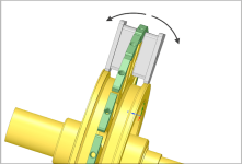
Might be a way though, with a flange like you said. Saddles that cup the core ends on the bottom, and give the core-
pair a wide base support to sit on. Then the center ring just locates everything more or less.

It would take a new axle with a thicker center, but could re-use everything else. Still just a thought at the moment.
(might be possible to modify the existing axle)

New Carrier. 2.png

New Carrier. 1.png

There could be a small ledge on the bottom that takes some of the stress off of the center. The idea being that the
cores would have to rock up and down each side in order to bend towards the magnets, which is less likely.

New stator 3..png

Food for thought.
 
I like the design, but if you're planning on that being one piece, Ti is probably out. Relatively thin plate is not too bad, but when you start upping the thickness to large diameter rod or billet...wheeeewww. I was thinking of a plate similar to what you have now when talking about my surplus material guy. He specifically has a lot of plate vs. rod.
 
No, this is just an idea for a back up plan, and would be made out of aluminum. Even at that, it would probably have
to be two piece. Turning it out of 7" round stock would make a lot of waste. (But would be the strongest)

Needs more thought anyways, I probably don't need all the hold downs, and I'm sure the idea can be improved yet.

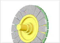
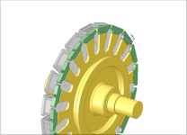
The plan is still on for the Titanium plate. :thumb: It will need to be about 8" diameter and .250" thick.
I just need to do the axial strength test's on the motor, (to be sure), and then tear it down so I can duplicate the the
stator plate in Cad, and send it off to you. I'm not sure if I can machine titanium,.. never tried, I've heard it's rough.

I have the motor back out of the bike, and I'm working on getting it mounted for the test now.
 
I was able to do the stiffness test on the rotor and stator today, but it wasn't all that conclusive. No night and day
differences anyway.

Using the 20 lb. load, the rotor assembly moved .003", and the stator moved .007". It was very difficult to hang any
weight from the stator because theres nothing to grab on to, and it's recessed. So I'll have to take it apart to put any
more weight on it.

But from that information, I can assume that the stator is about half as strong as the rotors. Either way they both seem
quite strong, and there must be an awful lot of force present to make it move the 2mm that I assume it's moving in
order to rub.

Next, I thought that it might be the bearings shifting somehow, or the rotor parts, so I gave it a side load test by pushing
on the sides with a long bar and a pice of wood. Nothing moved, slid, or shifted. It was extremely solid. I gave it quite
a bit of pressure, but didn't want to wreck it.

Rotor flex test..jpg

The only other thing I can think of is that the screws that hold the stator to the axle are only 5mm, and that they
might be stretching,.. but then the large washer is pressed and bonded to the axle, so that would have to flex too,
so I think that ideas out.

There is a remote possibility that the cores themselves are moving somehow, stretching the screws? I doubt it.

So, the only thing I can think of is that it must still be the fiberglass bending, and that it's time to go ahead and invest
in the titanium carrier. Time to take the motor all the way apart.

Any more ideas?
 
APL said:
Any more ideas?

I'm not sure how your motor is internally wired, but can't you use the electromagnet's force directly to measure deflection?
feed power to one side, and the reverse power to the other to get the maximum effect, and of course prevent it to turn somehow.

No need for a crazy amount of power, just a few thousand watts for a few seconds, just the time to see if something shifts or bends. I suggest you to put a camera on the side of the motor while doing it, so you can record a video and better analyze the results later.

If the video shows that the deflection is significant, then a possible way to measure it accurately could be to use some play doh paste, kinda the same way plasti dip works. You put some between the rotor and the stator, proceed to do the test I described above, and after that you measure by how much the play doh paste have been squeezed. Correlate this with the power you gave to the magnet and then you can extrapolate by how much it might bend under max load.
None of those tests are dynamic unfortunately, it is possible that the problem occurs because of some kind of ringing phenomenon at a certain frequency, but I guess unless you own a high speed camera you don't have much alternative.
I mean something similar to what happens in this video from the slow mo guys around the 6:40 min :
https://www.youtube.com/watch?v=zs7x1Hu29Wc

.
 
I was wondering something similar, if your poll configuration is causing it. I'd have thought the forces would balance out, that if the field was repelling on the left then it would be repelling with equal force on the right and the same for attraction but is there any possibility that's not the case? Should be easy enough to test, wire everything up static (no controller) and hook it up to a battery for a moment.
 
The attraction between rotor and stator will be a function of distance cubed or something like that so as the gap decreases the force increases tremendously. Any imbalance from one side to the other will be amplified as force greatly increases on one side and greatly decreases on the other side as the stator moves off center. Sort of a double whammy.

From your test I would agree that the fiberglass seems to be the main contributor.
 
It shouldn't be able to move, thats the underlying problem with this configuration. But the last fix made it stiff enough
to take 200 watts and run,.. so hopefully this fix will bring it up to 500-1000w and make it quite usable. I could be happy
with that for now.

I was hoping for big power this summer, but I think it will take a new carrier design to get that to really work well. Now
that we know the story, I can work on that a little later. For the moment though, I'm hoping that the titanium stator will
be successful enough to wrap this build up, at least momentarily, and give me time to build a new bike this winter.

I'm certainly not giving up on motor builds by any means, I love this stuff, but it's been two years,.. three since the last
bike build, and I'm getting the itch for the smell of brass and flux, and grinding steel. I'm thinking about moving over
to the bike build category in a few months, and maybe showing the frame build there over part of this winter. Get back
to building a completely new Axle/stator after that. Anyway,.. just some thoughts I'm having.

Hooking up some coils for a magnetic test is a good idea. I could do another test to try and get a visual, since I have to
take the coils apart anyway to get them off the stator plate. Might not have to re-wire much though, since it's just straight
DC. I would think that momentarily touching 12v or so to several coils on each side would do it.

I always wondered if you could take a motor apart that way too,.. basically it would disassemble itself, :lol:, but I haven't
really thought it all the way through.
 
Hello, APL, thanks for your 666 posts, very impressive! Maybe you could have a look at this thread, about Duyunov project: "https://endless-sphere.com/forums/...n motor, and combined winding star and delta.
 
Thanks for your interest Mobilis, and thanks for bringing the Duyunov project to the table. I looked it over, but all I
see is hype, and no hard facts, or an explanation on exactly whats supposed to be superior about it, and why.

The fact that it's been around for so many years, and still not in use today is another red flag. Generally, anything
that is an advancement in technology, and especially motor technology, is a very big deal. Even a tiny little bit.
All the major companies would not hesitate to use it in their offerings, and the news media and scientific community's
would be full of very detailed articles, and theory on the forces at play.

So until theres some kind of schematic, or detailed explanations, I'll have to hold off on very much interest in it.
 
Starting into the tare down, I noticed that the shoddy preload spacer that I rushed through, was a bit distorted
and may have been able to squeeze in and out under the outer bearing shell. Hmmm,.. didn't think of that. :oops:

That might account for it being able to move under high load, and then pop back. So now I have to do a better job
of spacing and shimming,.. then do another ride test, and see if it makes any difference.

I was able to find some steel machine bushings that are close to the right size, and hopefully will do the job. What
would be nice, is a shim-set of steel washers the right size for adjusting the bearings and gap.

Anyway, I don't want to get any hopes up too high, but it would be nice if this turned out to be the problem. :wink:
We shall soon find out. Otherwise, it's back on course for a new Ti. stator plate.
 
Preload shim washers are installed, and much more solid, but now a new issue shows up in the rotor/spacer screws.
I assumed that the conical heads of the flat top cap screws would index the rotors, but thats just not happening.
Theres enough slop in the threads, and movement in the heads, to allow the rotors to shift position on the spacers,
and the whole cage can move, depending on where you lock it down. Which means it can shift under load.

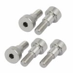
So the answer is to install shoulder bolts in their place, so the shoulder fits tight, and locks both parts in place. So
now I wait for parts to arrive, and a counterbore to do the job. It never ends,.. but thats the way it goes. :)

Shoulder bolts 5mm..jpg
 
APL said:
Preload shim washers are installed, and much more solid, but now a new issue shows up in the rotor/spacer screws.
I assumed that the conical heads of the flat top cap screws would index the rotors, but thats just not happening.
Theres enough slop in the threads, and movement in the heads, to allow the rotors to shift position on the spacers,
and the whole cage can move, depending on where you lock it down. Which means it can shift under load.

So the answer is to install shoulder bolts in their place, so the shoulder fits tight, and locks both parts in place. So
now I wait for parts to arrive, and a counterbore to do the job. It never ends,.. but thats the way it goes. :)

Shoulder bolts 5mm..jpg

I think it would be better if you were using a solid ring instead of those spacers.
Not only for strenght under load, but also for safety, you should consider it especially since you seem to have access to a lathe big enough to do it.

Thinking about cooling issues before even having made an actual load test wasn't very pragmatic, and there's always be plenty of time to drill holes in it later if it turns out to be necessary.
 
I agree. A solid ring spacer is the way to go. I didn't envision all the problems that separate spacers would cause.
A ring with recessed sides, so that the rotors fit down into it and can't move, is the fool proof way to do it, and
fairly common on axial motors.

Hindsight is 20/20,.. would've, should've and all that. Now that I have more respect for the forces at play, the next
design will have a few more changes like that. Things need to be beefed up quite a bit all the way through.

The problem is that a ring that size is not so easy or cheap to get, at least from what I've been able to source so far,
so I always favored the separate spacers, having seen others use it, and it seemed to work on the last motor.

It would take a 9-1/2" OD. x 1/2' thick piece of aluminum round, about 2" long, (aprox), before machining. I'll have
to take another stab at sourcing out a piece of aluminum like that, (solid, tube, or pipe.), if this new bolt "quick fix"
doesn't work.

Hopefully I can get the shoulder bolts to work good enough to move forward for now, then I can get the necessary
info needed for how well this SMC is working. If not, then the ring has to be the next thing to do.
 
The machining went well, and the shoulder bolts are installed. I'm real happy with the way it turned out, and it was a
necessary improvement. The rotors spin nice and straight, and keep the alignment under load.

I have to wonder if the bearing caps should get the shoulder bolt treatment as well. But for now, I think we can rule
out the rotor cage as being a problem.

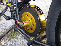
I put the motor back in the bike and took it for a spin. Only a slight improvement,.. I can give it up to 300 watts now
before it does it's rubbing thing, which is about an average draw for this bike, and good enough for 28 mph.

New test V2.jpg

So with all of that, I feel confident enough that it's indeed the stator plate thats causing all the grief, and it's time to
go for the gold, and get it replaced.

If the titanium is roughly six times stiffer than the fiberglass, then it should take six times the watts. Even half of that
would be a success.
 
Thanks for the comments, it's starting to look a little Frankenstein, with all the modifications, but still holding up.
One more mod. and hopefully we can start seeing some real power.

Plans are for a new battery pack that can deliver some more amps, and push it towards saturation, and an all new
bike that will look good with a motor like this in it' s hold. Just have to get over a few more hurdles.

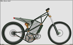
Heres a look at the frame,.. just a 2D sketch, as things are still being worked out. It has enough battery space for
two 26Ah batteries, (52Ah), and will take a 10" motor. Could be made bigger of course.
Looks off-road, but it's not.

Moto-Cruiser project..png

A low down, flat foot, Moto-Cruiser, with a bit of board-track mixed in. At least,.. thats the plan.
 
Back
Top