Question about "Maximum Momentary Pulse" for an 18650 cell

garolittle

10 kW
Joined
Mar 3, 2018
Messages
509
Location
Augusta, GA U.S.A
The spec sheet for the INR Samsung 25R cell (rated at 20A continuous) shows a "Maximum Momentary Pulse" of 100A. This may be a dumb question but would 100A be the "moment of death" for this cell? In other words, would hitting 100A kill the cell completely? Just curious. In practice I would never exceed 20A per cell (probably not even 15A per cell). That seems like a crazy high current level. Thanks for any comments. Gary
 
It will probably just put out 100A for an instant before the voltage collapses and current drops accordingly. No way I'm aware of that you can connect to an 18650 will tolerate that kind of current for more than an eyeblink anyway.

I wouldn't trouble myself about it.

If you want big currents, you're definitely looking at the wrong size cell.
 
Balmorhea said:
It will probably just put out 100A for an instant before the voltage collapses and current drops accordingly. No way I'm aware of that you can connect to an 18650 will tolerate that kind of current for more than an eyeblink anyway.

I wouldn't trouble myself about it.

If you want big currents, you're definitely looking at the wrong size cell.

Thanks. Appreciate the feedback. Was also interested in how to “size” the cell level fusing that I will use. Basically want to protect the driver (electric go kart) in unlikely event of a dead short situation. Max amps per cell will only be about 10 A. However I’m trying to figure out the ideal current level it which the fuse will “pop”. 100 A is clearly too high but is there a certain current level I should be aiming for regarding the fuse even though it is unlikely I will ever hit that level?
 
What buss bar ? Most would melt So a pack of 10p for a cart would be 1,000 amps. What controller do you have ?
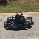
Kart what kart no pics ???
1,000a 72v 72,000 watts what kind of rubber you use ? On 10in tires. Ok enough.
 
Current / power output (or input) rating, peak or continuous, 0.01sec vs 10sec

needs to be converted to C-rate up front in any such discussion, in proportion to Ah / mAh energy capacity

whether on a per cell basis, or a 10P pack, whatever
 
LG M36 aka MJ1 would be a better choice for longevity

1C continuous, 3C peak

Samsung 35E, SONY VC7 pretty close if you find them cheaper

Do not use Sanyo GA, too inconsistent
 
garolittle said:
This may be a dumb question but would 100A be the "moment of death" for this cell? In other words, would hitting 100A kill the cell completely?
No. It'll be fine. That 100A spec is for 1 second bursts. Remember, it's mostly about heat. If the duty cycle is low enough to minimise heat production, then damage is minimised.
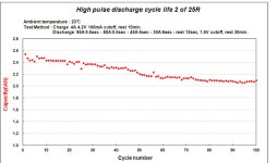
This graph is from the datasheet too. Lot of cycles of bursts of high currents. Deep discharge too. The cells can handle a decent amount of "abuse":
Screenshot_20200928-192454.jpg
The cell initial DCIR spec is 22mOhm. So maximum short circuit current is 190A.
 
It is always a good approach to do a simple math with DCIR. From the presentation sheet it should be about 20mR for Samsung 25R. This DCIR value gives an instantaneous voltage drop of 2.2V at 100A load. If you use simple BMS with instantaneous 3V cut-off voltage, you can get only up to 60A from fully charged cell to 4.2V before BMS will react. So your BMS must be aware of this and allowing to go lower than common 2.5V cut-off voltage.
 
999zip999 said:
What buss bar ? Most would melt So a pack of 10p for a cart would be 1,000 amps. What controller do you have ?
Kart what kart no pics ???
1,000a 72v 72,000 watts what kind of rubber you use ? On 10in tires. Ok enough.

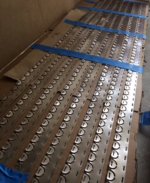
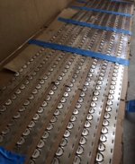
Sorry about that. Pictures attached. The busbar for the prototype battery pack is a SigmaCLAD material that is approximately 40% copper. The rest is mostly pure nickel. The pack will be 22S/20P and the maximum current expected is 200A (so 10A) per cell. The cell level fuses will be designed to pop at about 50A-60A to protect against a dead short. The cells used will be the INR Samsung 25R. Controller will be the Curtis 1234SE which is rated for 300+ A (max).
 

Attachments

  • IMG_0390.jpg
    IMG_0390.jpg
    67.6 KB · Views: 688
  • 4810FBC1-ECF9-4F47-BE83-CACB97EDFD73_1_105_c.jpeg
    4810FBC1-ECF9-4F47-BE83-CACB97EDFD73_1_105_c.jpeg
    125 KB · Views: 688
  • C90E8D19-BDA9-478B-A23F-924DC727DB3A_1_105_c.jpeg
    C90E8D19-BDA9-478B-A23F-924DC727DB3A_1_105_c.jpeg
    153.5 KB · Views: 688
john61ct said:
Current / power output (or input) rating, peak or continuous, 0.01sec vs 10sec

needs to be converted to C-rate up front in any such discussion, in proportion to Ah / mAh energy capacity

whether on a per cell basis, or a 10P pack, whatever

Roger that and thanks. The C-rate for the INR Samsung 25R cells is "8C". The pack will be a 22S/20P pack of these cells with a maximum current of 200A (probably about 175A continuous). Using cell-level fuses so just want to protect the driver (ie. give time to get away from the kart) if there is a dead short situation.
 
john61ct said:
LG M36 aka MJ1 would be a better choice for longevity

1C continuous, 3C peak

Samsung 35E, SONY VC7 pretty close if you find them cheaper

Do not use Sanyo GA, too inconsistent

Really like the MJ1 cells. Have not used them recently but may do so in the future. Thanks for the idea. May also try a 21700 size cell at some point.
 
serious_sam said:
garolittle said:
This may be a dumb question but would 100A be the "moment of death" for this cell? In other words, would hitting 100A kill the cell completely?
No. It'll be fine. That 100A spec is for 1 second bursts. Remember, it's mostly about heat. If the duty cycle is low enough to minimise heat production, then damage is minimised.
This graph is from the datasheet too. Lot of cycles of bursts of high currents. Deep discharge too. The cells can handle a decent amount of "abuse":
Screenshot_20200928-192454.jpg
The cell initial DCIR spec is 22mOhm. So maximum short circuit current is 190A.

Thank you! Really good response. The cell-level fuses are designed to pop at about 50-60A. I have tested this many times by creating a "dead short" with a single 25R cell and measuring the time it takes for the fuse to pop (about 1/2 of a second). It sounds like I am on the right track as far as the fuse is concerned but your feedback above is great information. Really appreciate that!
 

Attachments

  • IMG_0390.jpg
    IMG_0390.jpg
    67.6 KB · Views: 683
Pajda said:
It is always a good approach to do a simple math with DCIR. From the presentation sheet it should be about 20mR for Samsung 25R. This DCIR value gives an instantaneous voltage drop of 2.2V at 100A load. If you use simple BMS with instantaneous 3V cut-off voltage, you can get only up to 60A from fully charged cell to 4.2V before BMS will react. So your BMS must be aware of this and allowing to go lower than common 2.5V cut-off voltage.

Really good point. Thanks! :thumb:
 
Pajda said:
It is always a good approach to do a simple math with DCIR. From the presentation sheet it should be about 20mR for Samsung 25R. This DCIR value gives an instantaneous voltage drop of 2.2V at 100A load. If you use simple BMS with instantaneous 3V cut-off voltage, you can get only up to 60A from fully charged cell to 4.2V before BMS will react. So your BMS must be aware of this and allowing to go lower than common 2.5V cut-off voltage.

So this would create two layers of protection? 1) the BMS shuts cuts off at 60A (in the scenario above) and 2) the cell-level fuse (assuming it is sized correctly) will "pop" at 60A. Correct? Thanks for the comment.
 
999zip999 said:
Great garolittle Lot of learning here. I would love to see that. Cart live.

Yes Sir and thanks. I really like ES. This forum is a great resource for learning and for sharing ideas. Building a second prototype kart now. The first one was a blast. Check it out ...

https://youtu.be/b_kEQsOaJGc
 
A howto thread aimed at beginners, with links

on your cell-level fusing and

the other pack building details

would I think be a great resource for the community.
 
john61ct said:
A howto thread aimed at beginners, with links

on your cell-level fusing and

the other pack building details

would I think be a great resource for the community.

Yes Sir. It has been a long process and trial and error. Lacking high end equipment, I have performed fairly simple tests involving intentional dead shorting of a single cell (at a distance for safety). The goal is to determine the best size of the fuse "cross section" so that heat is minimized at max amps (10-15A per cell) but "pops" at a level that protects the pack (about 60-80A per cell). Willing to sacrifice a cell to improve safety. Still running lots of tests but will post more data once we settle on a final fuse design. Really appreciate all the help from this forum. Gary
 
I'm trying to say all my batteries can be a life-long experience like when you buy a parrot and last 100 years. So what batteries do you want and what weight you have to carry around.
 
999zip999 said:
I'm trying to say call me batteries can be a life-long experience like when you buy a parrot in last 100 years.

https://en.wikipedia.org/wiki/Nickel%E2%80%93iron_battery

Great for stationary electric vehicles.
 
Back
Top