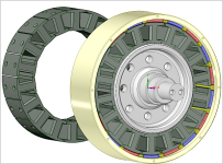
APL's DIY axial-flux motor

j bjork said:
ZeroEm said:
That is one good looking motor.

Agreed.
I dont have much to add, but I am impressed with your work :)

j bjork, I didn't make the connection at first, but after reading through your builds, I realized that I've enjoyed watching
them before,.. I hadn't seen the last one though. Very impressive stuff, and I envy your skills, especially your welding
abilities. Excellent builds, and I hope to see more of the same. :thumb:
 
The idea has been swirling around in the back of my head, ever since we started talking about SMC. But like the old man
down the road, I kept pushing it out of my mind. After all, this is an axial thread.

But it keeps coming back, and I finally gave in to the idea, and put it into pixels. Just for discussions sake, :confused: .. and it's
going to be a while until the stator plate is going to be done.

I never liked the idea of a DIY radial, because of the laminations, and the steel outer ring, or back iron. But with SMC,
the laminations are gone, and with a Halbach array of magnets, so is the back iron. Also, gone is the stator flex problem.
Another advantage is the non-trapezoid magnets, simple rectangles are plentiful.

The new problem becomes the number of cores that can be mounted, because of the SMC's low strength, and the actual
way to hold them in place, without bonding. It would be nice to be able to remove them for winding, and replacement.

Anyway,.. heres a first sketch of possible designs that I came up with,.. and somewhere to start. Have to say though, it
doesn't seem all that complicated. Anybody see problems? Ideas?

SMC Radial concept..png

The outer ring and hub can be aluminum, and the cores are segmented, creating their own inner back iron.
The motor could be made as wide as room allows.
 
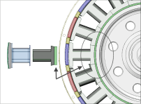
After thinking about it some more today, I thought that the core bottoms could be bonded to the axle if the top was
made separate. And it would be replaceable.

Perhaps a piece of .032" fiberglass on top,.. and the coil bobbin could be bonded to the bottom, to give it more strength
and keep it aligned.

Two piece core..png
 
Just a note on the backiron, too little inertia could cause major controller problems, I'd expect blowups from frequent sudden speed changes. Too much obviously isn't good either, unnecessary weight and sluggish acceleration, there's a happy medium in there somewhere but I'd er on the heavy side to begin with.
 
Been following for awhile, really enjoy the builds! With the most recent idea you can expect larger eddy current losses as the magnetic fields will flow through a "yoke", much like a conventional radial motor. Another idea would be to see if you can do relatively the same as linear labs with their HET motor. but using a non conductive pipe in the middle of the cores but instead of trying to make a totally "floating" stator only doing the inrunner and outrunner instead of incorporating the axial aspects too. Would be neat to see.
On the note of the HET motor in the small sizes they are currently being made it. Im still very skeptical on how it will perform, with no direct way to get heat out efficiently I see thermal issues in their future. But maybe they already have a solution. What are your guy's thoughts?
 
Stan.distortion, I see what you mean. Hadn't thought of that, but it's nice to be talking about not enough weight for once.
Here I thought that this motor was looking so good because it has the potential to be so light! Well, the good thing is,
that it's cirtainly easy to add weight. :)

And it might need "some" back iron anyway, according to the Things in Motion blog, Halbach by itself isn't quite as good
as it is with iron. Not a big difference though, .683 vs. .714 Nm. https://things-in-motion.blogspot.com/search?q=Halbach
I was hoping that it might not be necessary,.. because machining iron rings is such a pain, and it's so nice to be on the
light side for once.

Henery2000, thanks for the info., I wasn't aware of the Linear Labs HET motor per say, but I've seen others like it. Still
don't see how they mount the stator exactly, but it looks like they use brushes in the center.
Your right, they really have it closed up tight, with no cooling that I can see. Big power = big heat.

Linear Labs HET motor..jpg

I assume that your talking about the bottom of the cores where they touch the axle OD? I had my fingers half crossed that
it wouldn't be a problem, since most radials are pretty much the same sort of construction,.. laminated back iron mounted
on a steel yoke. But there is probably going to be 'some' eddy currents making it through the back iron to the aluminum?

I was hoping that it wouldn't be the case, but one way to go about fixing it is to use a fiberglass spacer bonded, or bolted
in between the two? Would rather do without it though.

Core insulator..png
 
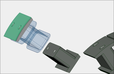
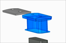
The newest idea is to take the 3D printed coil bobbin a little farther and design-in a two piece top, that glues together.
Glue encases the SMC shoe completely, and gives it much more strength and protection,.. helps to rust proof as well.
Now the top and coil can be removed as one unit.

3D printed shoe cover - bobbin..png
 
Well, all that may be a little over-thinking,.. two piece cores and coil holders. I'll stick with the solid cores for now,
and work on some other problems with the radial design.

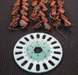
On the axial, I finally got the motor broke down to the basics again, the coils came out of it OK, and I shouldn't have
too much trouble getting them back in.

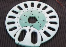
Stator plate out..jpg

Theres the suspected culprit,.. a weak stator plate. Now I can draw up a duplicate in Cad, and get a new one machined.
Then maybe we can get some long overdo results.
 
You'll need slots between the core hole and the outer edge. I like your idea of using a pin to keep the edges aligned. You could drill into the edge first, before making the slot. Not sure what the best pin material would be. Ceramic might be good but hard to work with and brittle. Very stiff though. Metal with a good insulation coating would also be possible. Either way I thing you'd want to glue them into the hole to minimize chances of movement.
 
Yes, the slots unfortunately are back again. Hate the slots but have no choice at the moment. Well, time to give it
more thought I guess.

Ceramic is tough to work with, your right. And not much availability either. Glass rod? Should be glued in for sure.
I could maybe anodize some aluminum pins,and paint them for a double coating. Otherwise I haven't had too many
other ideas.

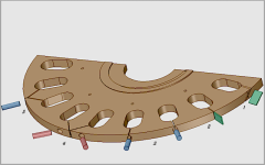
I've thought a little about different kinds of slot types, but haven't really found anything better than just a simple
slot and pin, like number 3, in this sketch.

Stator plugs..png
 
It looks like it would be a LOT of work to do the pins.

One other idea I had looks like your #2. Cut the slot at thin as possible and just fill it with epoxy. Much less work. If it fails, you can still drill it for pins later, maybe even without taking too much stuff apart. I really don't have a good idea of what forces are going to be on the slot. If everything is balanced, the force would be near zero. But it would never be perfectly balanced.
 
Thanks for the McMaster link coleasterling, the ceramic selection is awesome. I've been paging through the catalog for
hours! Looks like pins are no problem, but would have to be turned to size.
I'm not sure what "machinable" means to them, but I would hope that it could be done an a simple manual lathe, maybe
not.

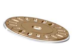
Well, I'll keep giving the slot cuts some more thought. It's possible to put a groove all the way around the diameter too,
and glue in something sideways in the groove.
 
I like the way it looks in the drawing, but I'm not sure about the real world version. The ring would have to be insulated,
of course, and un-closed. Just another posible idea.

Grooved edge..png

I've been told that Titanium isn't the greatest thing to machine, it work hardens and needs good cutters, etc. So it should
probably be kept simple if it goes that route.

Looking at this plate all the time, I think it might have been better to use 16 cores instead of 18. There might be more
room between them with thicker spokes on the stator. Part of the problem is that the strongest flux is at the top of the
trapezoid core which is cantilevered the farthest out.

Another thought is to use spacers between the cores, so the plate could be made thicker. A 4mm spacer would make a
10mm thick plate, approaching twice the strength.
 
I like the brainstorming around those kind of topic and your CAD drawing are nice to understand your solution !
I was just asking myself : Why do you need a pin or someting in the slot ? Aren't the cores sandwiched around this plate ? I don't think you'll lose rigidity here since it's not contributing to lateral stifness. But I might miss something
For the spacer between the core, they need to be ferromagnetic otherwise your increasing reluctance !

Keep up the good work ! :bigthumb:
 
APL said:
Looking at this plate all the time, I think it might have been better to use 16 cores instead of 18. There might be more
room between them with thicker spokes on the stator. Part of the problem is that the strongest flux is at the top of the
trapezoid core which is cantilevered the farthest out.

You can't use 16. It has to be a multiple of 3. 15 would be the next step down.

While the cores will help stabilize the slot, the core material is pretty weak and we don't want much stress on it. There will be a tendency for the cores to twist somewhat, which might make the edges of the slot to move with respect to each other. If everything is perfectly balanced, there won't be any twisting. It's hard to say whether it will be a problem and whether pins or other fixation will be needed.
 
Thanks Thecoco974, I know I show a lot of CAD drawings,.. I try to stay active with that, because it's a fantastic tool,
and I learn more and more as I go.

I realized that the cores actually do hold the slots together, your right, but theres only a 4mm screw going through
them, and it's only tight enough to secure them in place, which isn't very much, because the SMC is very weak, like
fechter said.

If I glued everything together it would help an awful lot, but it would be permanent. One problem is that the edge
can warp, or curve once cut, allowing some cores to move towards the magnets, while others don't.

The main problem with the slots is that the bottom of the spokes is the weakest part. Anything after that towards the
diameter is not helping much. If the top of the slots are connected , then the load is shared a little bit, but when they
are cut, then each spoke is on it's own, flexing from the bottom.

Stator weak link..jpg

it's not the greatest design,.. as I'm finding out the hard way, but it may still work. With the right strength, or stiffness
added through thickness, we may prevail yet. I still have a few back up plans.

As fechter stated, balance is the most likely key. The stator plate needs to be of a certain strength for sure, but after
that, it's up to balance.

Looking back at single rotor designs, we can see that the rotors don't have a lot of thickness to them, which means
that they are going to have the same problem that this motor has. So how do they get them to work? Must be balance?

Axial center rotor .png
 
Thecoco974 said:
.....
For the spacer between the core, they need to be ferromagnetic otherwise your increasing reluctance !

Keep up the good work ! :bigthumb:

Does the plate need to be non-ferromagnetic?? Late here so maybe I'm missing something obvious but wouldn't it just be back iron for the coils if it was steel? EDIT: It would need to be laminated wouldn't it, magnet back iron is a static field but the coils are changing?
 
The plate would need to be non conductive otherwise it would act like a 1 turn short. Lamination or slots would help. SMC stuff would be better. If the spacer was thin enough, non-magnetic stuff might not be too bad.

With the dual rotor setup, you get sort of the double whammy on pulling force balance. The attractive force will be a function of distance cubed or something like that so that as it shifts away from center, the imbalance grows quickly. If all else fails, use a bigger gap.
 
Ha! I was trying to say something like that a while ago, many pages back... a center iron dual stator, dual rotor axial.
Can't find it now, this thread is so long. :wink:

Center iron axial 3.jpg

I think I was wondering why you wouldn't have a shorted turn on something like that. Obviously the steel is making a
shorted turn between the cores. Sure it has to be laminated, or SMC, because of the AC signal, but still a short.

I think that what happens is that the magnetics switch from going through the plate, like this motor,.. to going sideways
between each other, on each side. And that somehow negates the short.

Might be a fix for this motor though, if there was a way to do it, although a bit heavier. I'd settle for that. :)

(Whats up with the coils in the pict. above? You can't do that,.. can you?)
 
The laminations make it not a short. That's why they use them. The iron strips are insulated from each other in the lamination. The orientation of the laminations is critical.

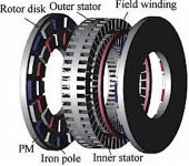
The motor in the picture looks like some kind of transverse flux thing where you have one big winding that goes over all the stator segments. There has to more than one winding to make it spin.
 
At a guess the picture is only showing a field winding, the coil windings aren't shown on the individual poles. I'd be curious how that looks in FEMM, it looks like there's something ingenious with variable field strength going on there but I'm not sure how. I'm assuming each magnet in a ring are the same polarity and the iron poles between them are the opposite pole. Not sure why there'd be an inner and outer ring though, it looks like the PMs are opposite polarity between inner and outer but the inner is bound to be less powerful than the outer. Maybe that's the point, the field winding is used to equalise strength?? Idk, at first I thought it might be a principle copied from an outrunner, 2 drums of equal strength with a field winding between them, I've never heard of anything like that so maybe it's an original design that exploits the difference between the inner and outer rings but I'd have thought it would be a whole lot easier to vary the spacing for a variable field on an axial flux motor.
 
Screenshot_20201007-141034.png

Hopefully that is a link to a download of paper about the subject motor. Looks interesting. Complex/complicated for ? gains.

Regards,

major

edit: link didn't work so here's a screenshot. Hope that helps.
 
Sorry, my bad, I should have included the link. Yea, it's for flux adjustment, as stated on page 17, fig 7.
https://ieeexplore.ieee.org/stamp/stamp.jsp?arnumber=7933123

All "over my head" stuff, and too much info for a DIY guy like me at the moment. Interesting though, and I've also seen
the coil in the picture above replaced with a copper tube, for water cooling.

As far as the double sided stator in the picture goes, I'm just trying to understand, not be argumentative, my point was,
that if the back iron between the cores is made thick enough, (still needs to be hysteresis free), then the flux path
changes from going through the plate, as my motor does,.. to going between the cores sideways, on one side, in a 'U'
shape. In which case there wouldn't be a shorted turn anymore. The two sides share the center iron as back irons. :?:

Also, any material that contains free electrons, (all metals), will react to AC current, by turning into heat and wasted
energy,.. depending on the amount of free electrons present in the metal.
Silver is the worst, titanium is best, there may be other exotics.

At the same time, motors are a compromise in general, and using some metals as a stator material as in this build,
may actually be acceptable to a point, such as aluminum, 304 stainless, or Ti. if the rpm is slow enough.
But the turn must still be cut, or it will "lock" the motor. I witnessed that in the last build.

Well, we are still working on sourcing the titanium, or I should say coleasterling is, and it's defiantly looking do-able
at the moment,.. so I think it's going to be a 'go'. Got my fingers crossed. :)
 
Back
Top