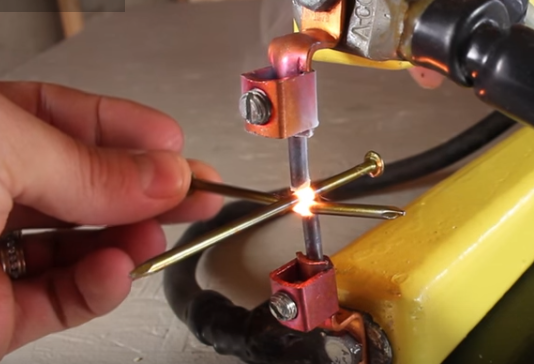
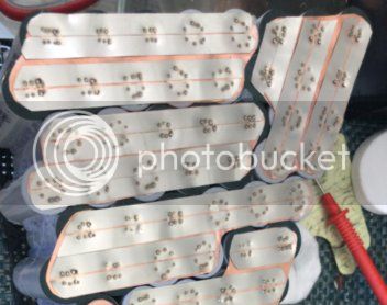
Spot Welding Copper Strips to 18650 Battery Cells

Make them in pairs and connect at opposite corners perhaps?
If you have tabs at diagonal opposite corners of the cuboid you could make pairs of batteries (2 x 38 cells) with mirror image plates, they can (for example) connect at the top at the front to access the bolted tabs and you lift a pair out to unbolt the other connected tabs at the bottom at the back.
Am assuming vertical plates coplanar, parallel to left plane, horizontal cells left to right.
You can still taper the conductors to reduce resistance
If you build it in this diagonal alternate nose to tail configuration, the total resistance to all cells is balanced, and easier to calculate as it's one full plate accross the diagonal for all cells.

I guess ideally, the plates should clamp together along the edges- thinking copper clamp bar and toggle clamps but I expect the forum will have some better ideas. It may depend on the mechanical method of supporting the batteries and needs to consider shock and vibration of course
 
spinningmagnets said:
I can only speculate as to why the copper/nickel sandwich works, but...for some reason it works.

from my observations i think the nickel sandwich works cause the nickel heats up enough to fuse the copper to the cell.

with straight copper to cell, it would only work with tungsten electrode tips. the tips could be seen glowing cherry red for an instant as the weld was created, but the weld was still cool to touch after.

tungsten gets hot cause it has quite high resistance, but wont melt.

copper is just so good at passing current and without getting hot that its very difficult to get it hot enough with standard copper tips.

with the sandwich, the nickel does the heating, and id say also may help by excluding the air.
it works brilliantly and gives strong welds, but still requires very high power and vary short pulse time.


i couldn't get diy plated copper to work, the nickel would just vaporise off and get bad welds.
 
ridethelightning said:
i couldn't get diy plated copper to work, the nickel would just vaporise off and get bad welds.

Correct. We even electroplated the copper with nickel ourselves. Tried several times. Never could get consistent welds
 
Update: I did a somewhat crude model in LTSpice of my 38P (now 40P for a square array) cell block with a 1200A load. I used measured resistance of nickel foil strips (using 4W milliohmeter) and then scaled and factored it up to 1.5mm copper plate (.060") I used a square array of 26650 cells 4 by 10, with a tab on top of 1.5". The idea is that this tab bolts directly to the cell tab next to it to create a series string of 112 cell blocks (112S 40P). As spinningmagnets predicted, the current is concentrated at the top of the block, with the largest voltage drop across the 1.5" long end tab. I can probably shorten it when I build it. The model includes the cell-to-copper nickel (.15mm) but it divides the copper bus into 10 sections, each one the width of a row of 4 cells. Each row of 4 cells feeds the bus as though the feed point is a line across the copper bus.

I'm attaching a photo of a marked up schematic with voltage and current calculations. The overall voltage drop came out to 34mV from the bottom cells to the top of the tab, although there is an 8mV drop across the last 1.5 inches of tab. My original estimate was 25mV. So when you multiply that out for 112 cells x 2plates per cell you get 224 x .034 or 7.616V! Granted, this 1200A will only last for a few seconds during max acceleration, but I'd like to limit it to 5V or less. The other interesting thing is the current sharing among cells. However, the bottom cells source 28.91A each while the top row of cells sources 31.89A. I used the average measured DC cell resistance for the cells for the model (7.8 milliohms). I was surprised to see a 10% difference in cell currents. I assumed the cell impedance would make the cells appear as constant current sources. Not so much. Interesting in that the top 3 rows are affected the most. The bottom 3 rows are almost the same. Makes sense when you look at the tapering current.

So my conclusion is if I go with these particular cells, a 2mm thick "holey"copper plate may be better, and the "laminated" .15mm nickel may be the most practical way to get from the copper plate to the cell. I may try a nickel-copper sandwich using the .15mm nickel and the 2.0mm copper plate once I get my kWeld but I'm doubtful.

I've attached a picture of the schematic marked up with voltages and currents. I need to try different cell impedances and different copper thicknesses.
 
67carguy said:
So my conclusion is if I go with these particular cells, a 2mm thick "holey"copper plate may be better, and the "laminated" .15mm nickel may be the most practical way to get from the copper plate to the cell. I may try a nickel-copper sandwich using the .15mm nickel and the 2.0mm copper plate once I get my kWeld but I'm doubtful.
yep, 2.0 copper is tig welding territory! though, if your lucky, you might be able to get the 0.15 nickel to weld to it, provided its well cleaned and you have enough power. if you insulate and preheat the copper plate with blow heater or heat gun while you weld nickel to it it might help. you could then let it cool before welding the nickel bridges to cells.. i will be keen to see how you get on
 
garolittle said:
ridethelightning said:
i couldn't get diy plated copper to work, the nickel would just vaporise off and get bad welds.

Correct. We even electroplated the copper with nickel ourselves. Tried several times. Never could get consistent welds

yeah, and it pisses me off because iv opened powertool packs to find they have spotwelded plated copper to cells very nicely
 
It's my understanding that Makita and others use nickel-plated copper so that the nickel provides corrosion protection, The nickel is thin, and does not help the welding. These manufacturers often use a laser-welding process, with a very expensive and fast machine.
 
So I've spent a week looking at this from many different angles. The spice model of the plate got me thinking. Then I estimated the cost of the plates, and their weight. All of a sudden my beautiful symmetrical single cell (40P) system doesn't look so great. The cost of the copper plates alone starts to get comparable to the cell cost, and the same for the weight of the copper plates. A 4x12 inch plate of .060" copper is HEAVY and EXPENSIVE.

BobBob suggested 2 cell groups. I think the multiple cell idea is the right way to go. To minimize all the extra packaging size, weight and cost, and to minimize cell interconnection losses, I'm thinking of going to 4 cell blocks per package (4S40P). Still a manageable size, and I'm thinking of maybe a 6x6 or 6x7 cell layout, and join the copper busses all down each side. So my series path is now no more than 3 cells long, compared to 10 cells long. I need to model it and play with packaging ideas. I'm also thinking that if the current density is reduced, I might be able to use the nickel-copper sandwich idea.
 
My idea for pairs of cell groups was to balance the resistance through the bus plates by drawing and supplying from opposite diagonals but with cells nose to tail the bus bars are potentially redundant which could be a weight and cost saving.

A big benefit of copper plates and nickel strip was that it took the path length to half that of normal nose to tail (1p2S configuration) as the nickel conducts in both directions. By taking the nickel to a bus bar accross 3 cells it travels 9, 27 and 45 mm respectively or average approx 30mm or 2-3 x further than average IE 4-6 x worse and different for the three cells.

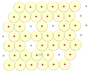
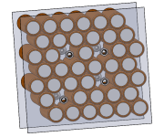
Wondering about connecting axially by missing cells and soldering (copper?) nuts to the nickel (nickel plate shown too big and transparent ) - that way you can bolt the plates nose to tail in the middle and weld the edges. No need for copper if the path length is short enough - CAD below to clarify.
Caveat: Any new design is risky, resistance should be better and weight and cost though density is missing 1 in 10 cells

It's possible to get an alen key through the nut to do up the next screw Note that I am absolutely not saying this is a good idea - just one for discussion from a bunch of people here who know a lot more than I do about battery pack build.

Pattern showing all conduction paths are less than a cell width
2d.png

One block as welded - interference hole on screw for retention and loctite 243
block.png
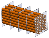
bolt the middle and weld the edges - not the easiest to disassemble. maybe clamp 4 together as well,
4 blocks.png

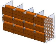
Section through blocks to show machine screws - M5 flanged cap heads use 3mm alen wrench
section.png

A simple alternative has 40P in a straight line nose to tail with the next 40 - just a big version of a standard configuration and then linked up with thick copper to the next pack - 10mm average nickel path length maybe? double up nickel, thicker nickel (maybe 0.3 etc) all easy standard approaches. No innovation = lower risk.

BTW apologies for hijacking copper welding with alernatives for the application.
 
Interesting development here. A year ago soldered individual cell fuses where all the rage. Now we have cu-ni sandwiches and frankly those make a much more robust impression for hi power cell packs. There should be a wiki or a sticky post with a quick howto: cu plate thickness, ni or better plated steel thickness, power level required to weld and a few examples.

Dumb question: how do you guys get so clean and regularly spaced holes through your copper sheet ?
 
I believe some punch holes. I'd laser if I needed accuracy. You could also clamp between two sheets of ply and drill. Most commonly available tech for that sort of accuracy is find someone with a mill and machine it.
 
Hole punch is by far the quickest and cleanest way for thin sheet/foil. Only problem is locating it exactly where you need it. A highly ordered layout would lend itself to an automated process, or a jig, or some other way of punching it all out in a very short time.
 
yes, sorry if this is temporarily hijacking the thread.

BobBob: Very interesting idea with machine screws in the middle of the plates. Took me a while to figure out why the screws don't short out the cells! You would want to use an INSULATED allen wrench of course....

I played around with copper thicknesses and voltage drops. It turns out I can get my 40P block very nicely as 5 cells wide and 8 cells high. The beauty in that layout is that I can pre-make my 40P cell blocks using 0.15mm copper and .1mm nickel plated steel (for cost). I can cut the copper sheets to be a square the same size as the cells (similar to your beautiful CAD drawing) and use the nickel/copper welding trick.

Even discounting the conductivity of the nickel-plated steel, the drop from the center cell to either edge is only 11 mV at 1200 amps. And If I weld the edges of adjacent cells together, There are no additional losses (per cell block) until I get to the end plates of the 4 cell blocks. I'm thinking I will set up a brute force spot welder to weld a few mm in from the edges, down the sides, in between the cells where there is a triangular space. The nickel-plated steel plates would be perhaps 5mm smaller on all sides so I can spot weld the copper-copper plates. According to the LTspice simulation, the drop is only 11mV so adding screws in the center wouldn't be needed. And I only figured on .15mm copper.

I'll have to glue up the cell blocks in advance, and then just weld the copper/nickel sandwich on them. The ends of the 4 S unit would get end plates per my original idea. But the 8x5 cell layout also helps cut my copper losses because the end plates only have 8 cells feeding the end vs my previous 10 cells. A good chunk of the voltage drop was in the last 2 rows, because ALL the current flowed through them.

Now, to refine this idea, I suspect the next trick will be to get the copper sheets laser cut with slots over each cell to aid in getting good welds, forcing the current through the cell ends. I'd love to avoid the laser cutting step, but I suspect the slots in the copper will be necessary. I could use narrow nickel strips in parallel with the slots in the copper, avoiding the cost of laser cutting larger nickel-plated steel sheets. They just have to be wide enough to take the hit from the electrodes.
 
Kaptan tape round the Allen key I guess, I'm not going to try to figure out how to weld plastic nuts to copper and nickel

Of course with a dead short you might get it to weld itself together, or a single bigger thread in the middle you could screw them together by spinning the packs. I thought about other types of connectors in the middle such as lasering and folding some large complicated bayonet twist lock but that's for another day and another project

More seriously
Agreed, 11mV is 0.25% loss and that's worst case, so average is way less than half that, so hefty plates and complicated solutions are not worth doing.

Wondering how big the nickel pieces need to be. (disposable probe tips?) My guess is that it's a sacrificial heating element to melt the copper and as such works in a similar way to ridethelightning's tungston tips in that it heats the copper and melts it. I'd think the steel will rust but I'm not sure how much salt spray the battery pack may see where you live - my experience of cars and rust might push me toward pure nickel but maybe smaller pieces. I noticed someone using little squares.

Ah - standardising - yup that's going to be critical - closed loop control (knowing how well it worked) is easier with strip because you can pull after each set of welds to make sure it stuck well, With a big sheet you can't do that and if you've already glued the cells together (and it's difficult not to) then you can't easily check adhesion and compensate. Without a closed loop, a process that is already less well understood than nickel, this all becomes more difficult to fully understand and therefore control.

Having a slot in the copper does at least allow a thin blade to probe and check it's stuck if there's also a slot in the steel / nickel.

Now if we put a smear of solder paste on the copper as a back up ... the heat would melt that and might stick it better - if it's hot enough to melt copper it might not need as much heat to melt solder - I haven't seen a lot on resistance braze and resistance soldering (sub second pulse) info on here - probably a good reason though I've seen it done in motor manufacture for stator wires - sorry - off piste again

I'm also wondering about the plastic covering on the cells. It insulates them from each other and then we weld them all together again - there's an arguement that by taking the plastic wrap off; the amount of electrical contact between cells on a 5x8 array is massively greater than foil accross the end so why bother welding? yeah, I know, glue - not so good a conductor and conductive glues generally not that great conductors or glues - guess that thought's a work in progress.

You could punch the slots I guess, bit small for a nibbler. dremel blade would take a while and rip things up, water jet, laser
Laser would seem to make life easier but it's not my budget.

Back on track - process control:
I'd work out the key process variables - the things that you have to control to get repeatable results. These may include the choice of cell, orientation, probe size, shape, probe temperature, probe material, probe cleanliness, pressure, variation in pressure, material preperation (cleanliness), flatness, roughness, copper thickness, nickel thickness, possibly steel thickness, distance between probes, probe position on cell, nickel or copper position on cell, material cutouts (slots etc), material temperature, voltage, current, current duration, ramp up and current profile. There will be others and we seem to have some info on half of the above already.

Some of the above may have little effect, others may only work well in a small window and some will be interdependent. Even if you start with all defined it might we worth bracketing (doing one test with a value above and below where you think it's best) to check it doesn't all go out of kilter with a small change or you may find an improvement.

Publish everything here (or of course optionally cover all useful data in green post-it notes and make your millions with your own special sauce combination of welder settings)
 
As BobBob states:
Back on track - process control:
I'd work out the key process variables - the things that you have to control to get repeatable results. These may include the choice of cell, orientation, probe size, shape, probe temperature, probe material, probe cleanliness, pressure, variation in pressure, material preperation (cleanliness), flatness, roughness, copper thickness, nickel thickness, possibly steel thickness, distance between probes, probe position on cell, nickel or copper position on cell, material cutouts (slots etc), material temperature, voltage, current, current duration, ramp up and current profile.

Yes, I couldn't agree more. 112 x 40 = 4480 cells. probably north of 50,000 welds before it's done. So my thought process on that goes something like this:

kWeld for all cell welding. Possible modified kWeld to do copper-copper end "plate" welds with tungsten electrodes. The beauty of this welder is that it calculates Joules delivered in real time. Eliminates SO many variables like voltage, current, duration, contact resistance, flatness, roughness, etc. I sprung for the fixed 12V supply with supercaps, which should give me a nice stable operating point.

I'm thinking I need to set up an X-Y-Z table with the weld head on it. Looks like a suitable X-Y-Z gantry is only around $700 (all HD aluminum, with servos). So position and head pressure will be very well controlled. Mainly for welding the end plates onto cell packs. Might still have to join the cell packs with a manual clamp-type spot welder. But I'm thinking the copper-copper welds won't be critical because I don't have to worry about puncturing a cell. I think I'll have to get the copper plates laser (or water jet?) cut, so all that geometry will be pretty much spot on. Positioning of the nickel shouldn't be critical. I saw reference to someone using squares, but the photo did not show any squares. Still curious on that one. I thought about corrosion, I'll have to try a salt water immersion test. It may be easier to stick with pure nickel. I had to scrap my last homebuilt EV because my custom welded frame rusted out. Not letting that happen again!

The biggest variable will be electrode temperature I think. I don't know how I can keep that consistent. Hmmmmm... just thinking..... maybe a test block off to the side. A tungsten block where before it starts welding 40 cells to an end plate it does a few rapid shots on, say, a block of tungsten to heat them up a bit.

BTW I was reading the posts on the thread dedicated to the copper/nickel sandwich idea. I haven't seen a lot of activity there.
 
I think you're on the right track, and also that there are some potential pitfalls.
Automation is a great way to avoid being able to compensate for things and so really gets you thinking about how to control the material and environment. This can be a good thing but takes more work designing the material feed rather than welding. Humans are amazingly adaptable which is a pain when automating.

If you have varying flatness, then putting constant joules through the workpiece may help but may not compensate enough. If the flatness is a problem, the resistance path may be longer rather than going straight through as a spot, the solution might be to press harder, have a pointier tip to the probe or put more joules in but the K-weld can only see a greater resistance so it puts a bit more duration in to the weld to compensate, but this won't be enough if the hot spot between copper and cell is 1mm off to the side and so the weld area is twice as big - it may need to put double the joules in, to get the right level of weld, but then you'd have a weld that put twice as much heat into your cell which you might not want.
The right way is to prevent the non flat piece of strip getting in to the process in the first place which is easy for machines to achieve but more difficult with tin snips.

It would be nice to get it to work without constant joules and then switch that on later...

So, steppers are cheaper and easier to control than servos and this probably isn't a dynamic application other than Z so you don't necessarily need servos.
Thinking a little old school due to budget, for a relatively simple method, an XY table with a Z axis using a pneumatic cylinder would give you accurate XY position but constant (or controllable) force without accurate Z position which may be better - the constant force compensates for some metal strip flex, tool wear etc so you get better pressure control than a servo for less cost. A Servo on the Z might give you force control at $700 but not sure how good it would be or needs to be.

A typical industrial servo, controller and actuator of this sort of size would be of the order of £2k (thinking Bosch Rexroth, SMC or or Festo eg ESBF-BS-32-100-10P or https://www.smc.eu/portal_ssl/WebContent/digital_catalog_2/jsp/view_descriptions.jsp?dc_product_id=164441 ) of course there are a number of other ways (distance compressing a spring for example) to achieve this. I am not suggesting you lay out 20K on automation hardware, just that there will be limits to the rigidity and precision of an cheap chinese system that has pros and cons. You might on the other hand be talking about building your own from motors, arduino controllers and some good old machined bearings and slides etc in which case a few weeks work will get you something really robust for $700 but there's a whole new thread in that build :)

Assuming a relatively simple bought in table, I'd spend more time designing tooling and fixturing than on the XYZ table - the repeatability of holding the bank of batteries flat provides the surface that you bond your flat piece of copper to. The spacing determines where the probe hits on the battery. The way you hold the copper and Nickel determine the relative position (you don't want to weld on the edge all the way along and puncture the centre row of a bank of 40).

An alternative configuration is an XY table moving the cells and a Z axis for weld heads - it will be easier if you don't have to move the welder in X&Y

A nice thing about starting with virgin material and lasering is that dimensions and flatness will probably be good which will help with contol and repeatability.

I've been assuming you're using the table open loop but if you want closed loop control you could do a lot with electrical contact from the tip. If that's the case I might agree on servos or three steppers and a spring on Z. Clever control can more than compensate for quality hardware but you need to be a programmer or control systems chap rather than machinist type of engineer.

System might then detect the position of the battery and position of the strip as touching the metal with the probe gives a signal which in the first instance tells you where the cell is if you laser some alignment holes in the sheet

This allows you to offset your welds so that they are in the right place on the cell. It allows you to measure the cell position (in case your glueing is out at 4AM) and compensate for X,Y or even Z misalignment which might involve bending the plate further in.

Next leve up in complexity - you could probably measure resistance and detect when the probe hits the nickel and when the nickel hits the copper though copper to cell might be tricky due to lower resistance. This might give you force compensation for material flatness. The first level of flatness compensation might be drive downward till second contact then apply 10N more force (2.2 lbf). The next level might be battery is 0.5mm offset so I have to bend the nickel to compensate so due to battery offset my force is contact plus 20N instead of 10 etc etc

The best control is to ensure that the variation in the material feeding in to the process is correct so you don't have to compensate. It's much easier to keep the metal flat than to work out how to flatten it or compensate for bent bits.
This means going back through the process to the previous step. Once all cells are identical, in a perfect array, everything is in exactly the same position etc the end process needs much less control.

Thermal control is relatively simple - heat it with a thermostat, stick a sensor somewhere relevant - perhaps a K type on the probe (electrically insulated) and blow hot air, stick it next to a nichrome wire heater, wrap in silicone covered nichrome or as you say, preheat - maybe on a copper block for tungston so the preheat is in the tips rather than the block.

Another thing I've thought might be worth doing is a comressed air jet to cool the weld directly after welding. Easy with automation, offset it by one cell and move to next cell immediately - you can cool the previous weld as you weld the next. Reduce cell damage from heat.
You should use a nozzle but it can be a simple one. this is where all the expansion occurs (so you cool the workpiece not the pipe) and use a direct nozzle not a venturi (used for cleaning - higher flow but not as good at cooling). You could also use this to cool the tips if needed so your temperature control was active cooling rather than active heating but inefficient as you're trying to get heat into the weld so hot tips are probably a good starting point.

Reckon the simplest would be an XY table with a, pneumatic Z axis, jigs to hold the bits in the right place and lasered bits so they're right in the first place.
 
Keep an eye out for a large microwave oven being thrown out. Size large would be good, but a medium will work just fine.

I'm suggesting that you make a spot welder for the two end collectors. You mention welding thick copper collectors to the positive and negative ends, connected to the copper bus-plate that is connected to the cells.

The kWeld is perfect for connecting copper strips to the ends of the cell, via the nickel sandwich. However, it is not even close enough to being able to bond the copper bus to a thick copper collector.

Building a brute-force Microwave Oven Transformer / MOT-welder may sound daunting, but it is dirt simple...

You find an old microwave oven, pull out the transformer, cut off the high-voltage coil (many wraps of very thin wire), then loop $20 worth of thick welding cable through it. Use 2, 4, or 6 turns...test and record. Each turn is one volt.

1500W = 2V at 750A
1500W = 4V at 375A
1500W = 6V at 180A

https://www.electricbike.com/resistance-soldering-unit/
SpotWelder1.png
 
BobBob:
Reckon the simplest would be an XY table with a, pneumatic Z axis, jigs to hold the bits in the right place and lasered bits so they're right in the first place.

I hadn't thought about a pneumatic Z axis but that would be a great way to get a controlled force. I was thinking of a spring-loaded head and a stepper type actuator. Fuyu Motion seems to have some nice stuff. All aluminum, seems well made. I just sent them an email. They even sell some of their parts on Amazon.

Lots of good thought-provoking comments. But in the end, I think it'll have to be laser cut sheets with precise slits. I'll need to make a dozen or so precision "cell nests" to hold the cells in place while the glue dries. Can't allow the 4AM operator to mess it all up. Still waiting for my kWelder. I'll want to try tungsten tips and direct copper welding, although I suspect the copper electrodes and the nickel strips will win out.

Spinningmagnets: A long, long time ago, I used to bring tools with me on the way to school so that I could remove the large power transformers out of the old B&W TV sets that were discarded at the curb. I used to cut off the high voltage windings and add a dozen or so turns with #12 wire to build "high power" 12VDC battery chargers. They worked great. I guess these days the preferred source is old Microwave Ovens! That's exactly what I've been thinking for welding copper-copper. I shouldn't need the fine control of the kWeld because I won't need to worry about puncturing the cells. I would only use it to weld the copper plates to each other, or the nickel strips to the copper plates on the ends.

My thought is to go back to the holey plate idea for the two end plates. With the 5x8 cell configuration, 1.5mm thick copper is plenty, and I might be able to live with 1.0mm. I would weld a nickel sheet over the holes, and I would weld the copper/nickel assembly to the cells using the kWeld. The current flows from the cell to the copper plate in all 4 directions, which greatly lowers the resistance of the nickel. The MOT welder would probably be used to weld the nickel to the copper plate, although I will try using the kWeld to weld the nickel to the copper. However, cellblock-to-cellblock would be a copper-copper weld, and definitely in MOT welding territory.
 
To play devil's advocate:
With 112 of something, automating the process is difficult to justify.
There was a story of a factory who built a factory next door for robotic assembly and in parallel got all their jigs and fixtures right and found it wan't worth automating in the end.

Welding takes around 0.1S to do 2 actual welds, twice for each end of each cell = 16 seconds welding per pack "value add" time or just under half an hour for the whole lot.

So, the justification for the automation is time taken positioning the probes and the fact a person has to do it instead of a machine. Assuming we can do the movement of probes (total) in less than the time taken to automate this leaves us with cost which should be lower for manual movement and gives us a better budget for tooling and fixturing:

As the cells move, the super caps have to charge so the process is limited by whichever is slower.

You could charge the super caps using a stonking (active FET) rectifier and an MOT to get it down to a second or two which is about right for movement. You might use the same MOT to weld the copper direct
You could also get a second K-Weld so you can do all 4 welds in one hit (4 probes) in half the time but 2x the cost - still cheaper than the XY stage.

An alternative is switching between two sets of probes using FETS in the probe. you need two banks of caps or a bigger MOT. The selector FETs don't have to switch fast so no clever drive circuitry. IPT004N03L handle 1200A for short bursts

Fixturing
If you put guide holes in the lasered sheet then you guide the weld head to position with 2x tapered pins that go through the holes and between the cells - that way every weld is aligned to the cell and plate.

Alternatively you could 3d print a holder and drop the sheets into that before fitting it over the block of cells - holding everything in place and providing some guide holes in the plastic for welding through.

Mount the weld probes on a drill press with spring loading and in theory you do 4x welds a second and finish both sides of a pack in a couple of minutes - half a day welding and you're done.
You'll probably spend more time glueing.

The 3d printed end caps (holding the copper and nickel plates) could double up as jigs for glueing so the assembly is done in one hit. Getting a good flat reference plane is important for one end.

Manual movement, Electrical selection of multiple probes
An alternative would be to have a block array of sprung probes and switch between them - 10% of the movement needed, just a single FET per probe pair to direct power - you could have (for example) an array of 20 probes, 10 FETS and do all the welds on 5 cells between movements. One K weld, a bank of MOTs or drive the KWeld direct from the MOTs. Circuit is simple, when the Capacitor charge reaches a target value, fire and index to next set of probes. When you can weld 20 at a time, do you need automation on X/Y?
 
I’m doing the sandwich....
0.1mm pure copper sheet/foil
0.2mm pure nickel x 8mm
I figured this cross section should give zero
“C rise” to 75-90 amps
100-140 amps with some loss to heat
160 amps max

I have a 30amp BMS. 35 miles on the pack so far.
Not even warm to the touch when asking 30amps.

60 Jules and using 3 LiFePO4 12.8v nominal 9.6ah packs to power the Kwelder 1500-1600amps draw from Kwelder.

iB0Yic8BQm_dalxeZpIQtQ.jpg
 
Tommy L:
I’m doing the sandwich....
0.1mm pure copper sheet/foil
0.2mm pure nickel x 8mm
.
.
.
60 Jules and using 3 LiFePO4 12.8v nominal 9.6ah packs to power the Kwelder 1500-1600amps draw from Kwelder.

Well that's encouraging! Only 60 joules... I'm hoping I can keep the peak current around the same and just extend the time a bit to be able to weld a .15mm copper/.15mm nickel. just curious: Why so thick on the nickel? Was it simply availability or did you need to go that thick?

BobBob:
To play devil's advocate:
With 112 of something, automating the process is difficult to justify.

True. BUT, in defense of my silliness on the automation front, this is, after all, a hobby (at least, for me it is). That means I really should enjoy it. I really enjoy building the car. I really enjoy designing the battery. My day job is technical and interesting, but I don't get to set the rules very often. Doing 112 x 40 x 2 x 2 = 17920 repetitive cell welds does not sound exciting, or interesting. I'm thinking I would likely stop enjoying this after perhaps 100 welds... I'll be honest, I had not considered some fixturing aids to manually weld them, but I don't think that would help enough. Now, rigging up an X-Y table to automate the process and allow me infinite flexibility, now THAT I think I will definitely enjoy.

Plus, there's the whole issue of quality and repeatability. I really want to make sure I don't blow a hole in a cell. Or slightly miss one. Automating it is a great way to get consistency. And, to be honest, I was shocked at how inexpensive a simple X-Y table is to build. So I'll have fun, I'll learn something new, I'll get a better battery, how can I go wrong???

So tonight I'm wrestling with whether to go with an AC spotwelder (AKA MOT) to do the copper=copper welds, or whether I should build a monster switchbank as ridethelightning did. My day job is in power electronics, so I am aware of all the potential pitfalls of building a 10,000 amp switch. Although I don't happen to have a defunct Microwave oven handy, I do have an old 20 amp Variac autotransformer which is mechanically on it's last legs. It's basically a nice big toroid just begging to have some welding cable wrapped around it... I need to do some research, I forget the advantages of AC vs DC spot welding.
 
67carguy said:
So tonight I'm wrestling with whether to go with an AC spotwelder (AKA MOT) to do the copper=copper welds, or whether I should build a monster switchbank as ridethelightning did. My day job is in power electronics, so I am aware of all the potential pitfalls of building a 10,000 amp switch. Although I don't happen to have a defunct Microwave oven handy, I do have an old 20 amp Variac autotransformer which is mechanically on it's last legs. It's basically a nice big toroid just begging to have some welding cable wrapped around it... I need to do some research, I forget the advantages of AC vs DC spot welding.

save your self the bother, iv been there.
its not so simple to get a transformer style welder to work well. issues with intermittent double pulse due to ac waveform and solid state relays, the type of core and air gaps etc make it unpredictable due to reluctance etc and bottom line just not enough power.

im super thrilled with the 72 mosfet array i bought plus timer board, all together around 100usd i think and still for sale. if i diddn't have a huge pile of half baked 25r cells, i would have bought some high discharge lipo packs to power it.

all i did to upgrade the thing was bolt some different copper pads to it to get a better connection and add some huge cables i got for /kg price at the scrap yard. the tips can be made from some 8mm or 10mm round bar and filed to point.
(oh and the protection diodes)
foot pedal is equally "sophisticated" - microswitch from microwave oven door glued to a chuck of wood, a hinge and a bit of spring steel flat strap

https://www.yousun.org/product/mini-spot-welder-time-controller
https://www.yousun.org/product/spot-welding-72xmosfet-switch
 
Back
Top