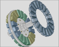
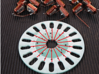
APL's DIY axial-flux motor

Hi APL,

Actually laminations are used to minimize Eddy currents, not hysteresis loss. Hysteresis is dependent on metallurgy, not shape. Eddies depend on the path and resistance of the path as well as the path orientation to the changing magnetic flux.

Eddy current and hysteresis losses are two district processes not dependent on each other or due to the same root causes, but both highly dependent on frequency and flux density.

major
 
Thanks major, your right of course. :thumb:

Dang it, I didn't notice that there was a new page, and edited my last post. Now people don't know what were talking
about. Sometimes I come back and edit, because I tend to blab on and on about nothing,.. got caught this time. :confused:
 
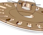
I'm drawing up the new Ti. stator plate in CAD so it can be CNC'd, and got to thinking about the metal cores contacting
the titanium surface. It occurred to me that it's probably going to short out the slits being put in the plate.

I should probably put some Kapton tape around the core bottoms to insulate them. Which means that I have to allow
for a little more slot OD. machining room.
Or I could paint one or the other. Or maybe all I need is a small piece of tape at the slit location?

Grooved edge. (1) copy.jpg

Any thoughts?
 
Right. The core itself isn't conductive enough to cause significant eddy currents. It should be OK. I suppose it wouldn't hurt to try measuring the resistance of a chunk of core. I think it's one of the specs in the datasheet.
 
It is slightly conductive, which is why I had the question, I had measured it a long time ago. But I just got done measuring
it again, and it jumps around incessantly but I get readings anywhere between 20K and 200K ohms. More or less.

So your probably right, and since the voltage in the loop is is small and the amperage is high, it probably won't short the
gap.

Looks like Micrometals has changed their page since I last looked at it. No mention of conductivity. But here it is anyway.
https://www.micrometals.com/products/materials/-40/
 
In the meantime, I've been working on the new bike frame details,.. and some Ideas for a possible Version 3 motor
stator assembly, nothing really new yet, just a collection of old and newer ideas.

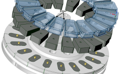
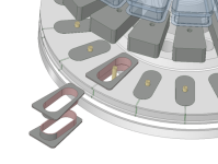
In this stator concept, a 10mm (thicker) aluminum plate is used, and the spacers and standoff's are glued into it, and the
main core body's are glued on top of that. This should all help to solidify the plate and make it stronger, as it all becomes
one piece.

The only thing removable are the coils and bobbins. The tooth brims are bonded into the coil bobbin tops on each side,
and slide on and off the cores.
The plate body is still aluminum though, so the design still has an Achilles heel. I'm trying to think of a way to possibly
reduce the reaction between the core and aluminum.


Version 3 concept..png
 
The top of the cores and magnets are far enough away from the plate, so the brunt of the eddy effect is the AC flux
going through the metal plate at the core center.

The effect is reduced with distance, I wonder if it's possible to bring it into acceptable amounts with a few millimeters
of a plastic spacer. A symbiotic relationship, or just wishful thinking?

Eddy reduction spacers..png
 
Sorry I'm going off topic a bit, but since you have the core making ability why not making an inrunner axial next ?
the dual rotor ourunner is really good for coreless since you can have plain steel yoke behind the magnets to close the magnetic circuit. With magnetic core this magnetic flux path closing can be done on the stator giving the oportunity to have a sealed inrunner with good thermal charactéristics since the outer shell is in direct contact with the core and coil. The construction might also be easier since you can go as crazy as you want with a thick aluminium rotor preventing flexing and the need for difficult one turn short avoiding technique.
I think this topology has been discussed in this thrad before but I can't remember why it was a no go. Here since it's becomming the norm a CAD of what it could look like :

inrunner.PNG
(stators are symmetrical)
 
Thanks Thecoco974, that's a good idea! I was just thinking that we might be needing a new approach, because this
design is getting forced a lot, which is not a good sign. Good designs should fall together.

I probably didn't lean towards the inrunner, because it's harder to mount in the bike, but I do like everything else about it.
Solid core mounting, with cooling, and simple rotor/axle.

I'm not sure about the rotor though,.. can it be made really thick? I thought the magnets on each side of it need to be
connected through cut-out's, giving it the same problems we have now. (weak support) Another reason I passed it by.

Single rotor support..jpg

If I use back iron to connect the magnets on the rotor, then I get excessive weight, as I will have three or four back irons
in the motor. I could also do that on this motor, as Stan.distortion suggested a few pages back.
It may still be a viable idea, if I forget about weight. A few more pounds on a 60lb bike isn't going to change much.

A single sided stator inrunner could be a good idea, if I can get enough power out of it, I'm not sure if it can compete with
the dual for power.

Anyway, I'm going to give these other axial designs some more thought. :thumb:
 
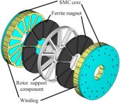
After seeing the cores in your drawing, the SMC back iron idea for this design seemed like it might actually work
better. So I tried it in a drawing, and I'm impressed, things fall together and nothing fights anymore!
It can use a 1/2" thick center plate or more, and one SMC section could cover three cores. Symmetry.

V3 SMC backiron..png

Heavier, and bit wider, but it looks like it can be made to handle some real power. I'm liking it. :)
 
I like the 3 poles per piece concept. For the rotor, your limiting factor is probably still going to be stiffness. Magnetically you can make it very thin but it needs to be super rigid. It needs to be thicker toward the axle and can get thinner toward the outside edge. If the back iron was fairly thin you could have a thicker hub section made of aluminum or something lighter.
 
Not sure if theres some confusion here. The sketch above is for a dual rotor, and is the same as the motor I'm building
now. I didn't draw in the cores on the other side. My bad.

Anyway, I finally figured out that if I get a 10" square piece of 2" thick aluminum plate, I can make both the stator and the
"one pice" outer spacer ring from it, as Dui, ni shuo de dui has suggested, and make the rotor cage super strong.

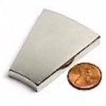
The other idea I'm having, since it's looking so robust, is to maybe use the windmill magnets I found a while back. :?:
Make the motor bigger, fatter, forget about weight, and go for the power,.. since the new bike should have plenty of it.

2%22 x .250%22 Wedge magnet..jpg
https://www.magnet4sale.com/n42-wedge-neodymium-magnet-od8xid4x0-25-22-5-degree/

The new magnets are big though, so I'd probably have to settle for 16 poles per side. But because of the torque I'd have to
go to a single cog in the rear anyways, so gearing will take care of the higher rpm.

I'm not sure if all that is a good idea yet,.. but maybe. :confused:
 
I'm also not sure how it would be wired up yet, as it's basically two separate motors in one, back to back. The coils
could be wound together on each side, or the two sides could be wound separate, but phases connected parallel.
Or, the cores and rotors on each side could be shifted one half coil span, and possibly get smoother running and cogging?

Another possibility,.. since the plate would be thick and solid and plenty strong, is the edge could be machined into fins
to help with cooling.

Stator fins.jpg
 
For me an inrunner is lot easyer to mount inside a bike, no dangerous rotating part, lots of mounting points and cables aren't awkwardly need to come out of the axle. The rotor Can ne build a lot of different ways, since their is a simingly invariable magnetic field going through it, no need to use lamination nor SMC just plain Iron/Steel between the magnets or only a thick one all the way through. ( I might be wrong about this )

I like tout Idea with 3 cores machined together, it's really looking like two single rotor back to back. If strong enough you could make them shifted for a smoothness equivalent to double the pole pair count but in that case it would be better to run each stator individually. (Two controller isn't a Bad Idea, you Can pick two smaller one for cheaper than a Big one in most cases). If they're in line then they should be wired in series or be extremly well balanced to avoid recirculating currents in parallel.

Envoyé de mon Redmi Note 9S en utilisant Tapatalk

 
I think your right about that Thecoco974, Theres no reason to have a thin or machined rotor between the magnets, unless
you want to run the flux path through it. I guess it would be lighter, but a thick iron rotor will work too, the flux path
would 'U' over to the next core and have a shorter flux path, and the other way would have a longer one, but both would
work the same I think.

A thick iron rotor might be best for DIY though,.. strong, cheap, and less to machine. Probably easier than what I have
now. Your also right about running the phase wires, theres no size restrictions or difficult routing on an inrunner. Another
possibility with inrunners is the ability to switch from delta to "Y" phase wiring while its running, because of heavy wires.
Hmmm, I guess I'll have to start a drawing and see what it might look like. :)

I'm also liking the way this motor is looking, and it really is 'two' motors,.. although the inrunner is too, they both have
multiple wiring options. The core skewing is interesting and would be fun to try, although I'm not sure if it has any real
benefits, at least, for a bike. :?:
 
I colorized the core sections in this drawing, to show how they're wired together. It's like a three-cylinder of 3's. :wink:
The 'tri-core' sections work well with that, and could possibly be removed as units,.. each with only two wires.

V3 Phase pattern..png
 
I'm sure it's already been discussed elsewhere in this thread (TLDR), but are you using any motor design software or are you just going off of experience? This is an extremely interesting project!
 
I'm wondering if you considered this weird option:
asasd.png

The idea would be to cut towards the center instead of the outer perimeter. This way it would probably have much more strenght since most of the forces act near the outer perimeter, and you could clamp the center very tight without having to change anything but to add some kind of insulation between the stator plate and the flanges. Sice the current flanges are large, only a very few portion of the slot would be unsupported, and since it would not be at an extremity then it should almost not flex at all.

I think it would be much easier to build (no pin necessary, basically the whole thing could be laser cut or waterjet cut) and pretty much directly plug and play on your current motor.
 
Thanks Stiffler359, no, I'm not using any design software, I'm using the awesome help and experience of others here
on the ES. :thumb: (and a LOT of internet searches.)

The point I would like to make is that this could be an interesting hobby for anyone, and that you don't necessarily need
to know all the technical formulas that motors encompass, if your willing to put up with a 'few' failures along the way.
I've had more than a few,.. but it makes the successes even better. No different than any other hobby.
(Patience is required though) :wink:

The beauty is,.. when it's all done, you can put it in a bike and get pulled down the road with a smile on your face! :D
 
I hadn't thought of that way Dui, ni shuo de dui, it is interesting though! It wouldn't be very strong by itself, but you're
right,.. once the center was clamped down, it might be stronger than the outer-slit method.

I'll give it some thought. The only thing I can think of at the moment is that it might not be so easy for me to do with
titanium, at least with the tools I have here. Waterjet would work, of course. I'll have to wait and see what this stuff is
like to cut when I get it. Aluminum would be no problem though, of course.

A waterjet appears to be the 'tool of choice' for making motor parts, and I'm still searching for parts to make one,
mostly for cutting magnets.
Pressure pumps are plentiful and no problem, but I've decided that it needs a CNC table to be really useful. There are
some fairly cheap tables that can be converted, such as for wood routers, low power laser, worn out plasma, and even
a 3D printer may work. A lot to think about, but yea,.. I could just pay to have it done too.
 
We have a really good, semi-local waterjet vendor, just lemme know what you want to do.

Tolerances on any waterjet work that's not going to cost WAY too much money are, at best, about 0.010". That's fine for most of the project, but maybe not the core slots.
 
If it's not too hard to make, slots going inward seem like a good idea. You're going to have to sandwich the center part of the stator anyway so it should be plenty stiff. The slots don't need to be very precise either. I was thinking hacksaw, but a water jet could do the entire part. If the core holes need to be more precise, you could water jet them a little undersize and machine out the rest. You could also make them a little oversize to ensure the cores fit and fill the gap with epoxy.
 
Maybe get a 3d printer before looking into the water jet stuff, they're not as simple as they seem but the motion control stuff from a printer would carry over. Tbh I'd look into a plasma cutter table before water jet, nothing like as potentially accurate but still very useful and has many of the same issues, experience gained from that would go a long way towards getting a water jet up and running reliably. Maybe consider robot arm kind of configurations instead of more conventional sliding axis too, with CNC control it's trivial to get straight lines with those kind of machines and they're already taking over for "dirty" jobs in some industries (stone cutting for ex.).
 
Back
Top