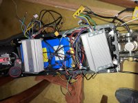
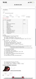
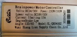
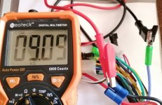
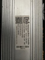
XLD Brainpower motor controller XunLiDa

If the motor is running poorly try using the self learning feature. It is 2 green wires. Connect them and turn on the controller. It will slowly spin the wheel till it has figured out the correct settings. When it starts spinning good, turn off the controller and unplug the green wires.

Also I just got one of these controllers off Amazon. Gonna wire it up today.

Edit: Got it wired up to my bike. For those who care you can use Alarm Power to hook up your lights. Also, at least on my model, there is a noticeable increase in speed from gear 2 to 3.

Also my controller is doing something weird. When I use the self learn wires to calibrate the controller, while learning it will spin the correct way (forward) but then when I disconnect the wires it and turn it back on, twisting the throttle causes it to go backward. Shorting the reverse function causes it to go forward... :lol:
 
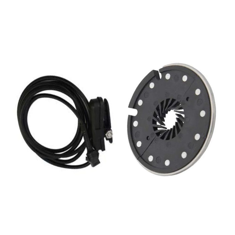
Hi guys, so I own a XLD Brainpower rated at 350w and a 12 magnets P.A.S (KT), this model :

HTB1iXdBXOrxK1RkHFCcq6AQCVXaU.jpg


It works with a throttle, but when I connect the P.A.S instead, the controller doesn't respond. are those controllers incompatible with magnet pedal assist sensors ?

thx
 
atkforever said:
Hi guys, so I own a XLD Brainpower rated at 350w and a 12 magnets P.A.S (KT), this model :

HTB1iXdBXOrxK1RkHFCcq6AQCVXaU.jpg


It works with a throttle, but when I connect the P.A.S instead, the controller doesn't respond. are those controllers incompatible with magnet pedal assist sensors ?

thx

Did you change the P10 settings?
 
Hi. I'm using controller 1200w 45A limit. Setup is little different from that we see on the road. 60v battery with that xld controller, run an modified alternator, witch can handle up to 100v and 120A current. Everything is more than i suspect. Have some problem, mostly because of my lack of knowledge. For now I have only two questions. First: when driving, and xld hit current limit,...what is the manifestation on limiter? Those it cut the power or simply keep motor runing but deliver only amp below limit?
Second question : Alternator can achive high rpm, but, xld nicely rase rpm from almost 0, but goes to abouth 3500 - 4000 rpm and hit some limit. It doesn't meter is there a load or not on motor. Try'd with wires for selecting speed, and can get low speed. I notice with trotle pot that V goes from 0.8 to 3.8, but xld reaction is between 1.2 and 2.5. Everyting above 2.5 just doesn't change anything in speed.
I'm stuck with those problems, and have no clue what to do next.
Electronics is my hole life hoby, so there is no problem to mod xld (if that is possible).
Battery is 60v 20ah with very good bms.
Thanks guys 😊
 
Bane66 said:
Hi. I'm using controller 1200w 45A limit. Setup is little different from that we see on the road. 60v battery with that xld controller, run an modified alternator, witch can handle up to 100v and 120A current. Everything is more than i suspect. Have some problem, mostly because of my lack of knowledge. For now I have only two questions. First: when driving, and xld hit current limit,...what is the manifestation on limiter? Those it cut the power or simply keep motor runing but deliver only amp below limit?
Second question : Alternator can achive high rpm, but, xld nicely rase rpm from almost 0, but goes to abouth 3500 - 4000 rpm and hit some limit. It doesn't meter is there a load or not on motor. Try'd with wires for selecting speed, and can get low speed. I notice with trotle pot that V goes from 0.8 to 3.8, but xld reaction is between 1.2 and 2.5. Everyting above 2.5 just doesn't change anything in speed.
I'm stuck with those problems, and have no clue what to do next.
Electronics is my hole life hoby, so there is no problem to mod xld (if that is possible).
Battery is 60v 20ah with very good bms.
Thanks guys 😊

controller has 3 wire connector which has combinations, low speed, medium speed, high speed (unlimited). colors of wires are white, black, gray(?). I dont remember how they need to wire to get high speed. just test.

EDIT: explanation is in first page of thread.
 
pavlik1 said:
Hello

Just to confirm when DS and X are connected, the regenerative braking is working. The brake is connected to the provided wires outside the box.


Thanks to philf for all the effort.

wow. thats valuable information. Thank you all!
 
so this is my controller from an ebay kit, from this thread i understand that connecting the X and DS will activate EBS or possibly regen braking. so i connected them with a button so i can turn the feature on and off, my throttle is a key ignition that displays the voltage, when the system is powered up, the voltage is static, when i throttle it the voltage drops, and when i activate ebs via the on off button, then hit the brakes, the voltage goes up by 1-3 volts roughly, until the bike has come to a stop. so my questions are,

1) there are 2 mystery connectors, a 3 pin and 4 pin, i believe the 3 pin to be PAS, but i have no idea what the 4 pin is can anyone help me figure it out?

2) it is also to my understanding that if i connected k1 to ground i will be telling the controller to give me low speed, and i fi connect k2 to ground i will be telling the controller to go at its fastest speed, and i fi leave it as is, i will be going medium speed? if this is correct, then if i were to add a button that or a switch that the shorts k1 or k2 or leaves it open, i will in theory have a speed control of some sorts?

thank you for any clarity anyone can provide, i must admits trying to figure out the pins and their purposes was a pretty fun experience, almost liek solving a puzzle lol

uppy.jpg
 
edgefx1 said:
so this is my controller from an ebay kit, from this thread i understand that connecting the X and DS will activate EBS or possibly regen braking. so i connected them with a button so i can turn the feature on and off, my throttle is a key ignition that displays the voltage, when the system is powered up, the voltage is static, when i throttle it the voltage drops, and when i activate ebs via the on off button, then hit the brakes, the voltage goes up by 1-3 volts roughly, until the bike has come to a stop. so my questions are,

1) there are 2 mystery connectors, a 3 pin and 4 pin, i believe the 3 pin to be PAS, but i have no idea what the 4 pin is can anyone help me figure it out?

2) it is also to my understanding that if i connected k1 to ground i will be telling the controller to give me low speed, and i fi connect k2 to ground i will be telling the controller to go at its fastest speed, and i fi leave it as is, i will be going medium speed? if this is correct, then if i were to add a button that or a switch that the shorts k1 or k2 or leaves it open, i will in theory have a speed control of some sorts?

thank you for any clarity anyone can provide, i must admits trying to figure out the pins and their purposes was a pretty fun experience, almost liek solving a puzzle lol

Not sure about the regen braking, I have yet to figure that out. About the speed controls, yes. If you short all 3 - low speed; leave everything disconnected - medium speed and keep the two cable connected- max speed.

Sent from my SM-G960U1 using Tapatalk

 
Chintan_joey said:
edgefx1 said:
so this is my controller from an ebay kit, from this thread i understand that connecting the X and DS will activate EBS or possibly regen braking. so i connected them with a button so i can turn the feature on and off, my throttle is a key ignition that displays the voltage, when the system is powered up, the voltage is static, when i throttle it the voltage drops, and when i activate ebs via the on off button, then hit the brakes, the voltage goes up by 1-3 volts roughly, until the bike has come to a stop. so my questions are,

1) there are 2 mystery connectors, a 3 pin and 4 pin, i believe the 3 pin to be PAS, but i have no idea what the 4 pin is can anyone help me figure it out?

2) it is also to my understanding that if i connected k1 to ground i will be telling the controller to give me low speed, and i fi connect k2 to ground i will be telling the controller to go at its fastest speed, and i fi leave it as is, i will be going medium speed? if this is correct, then if i were to add a button that or a switch that the shorts k1 or k2 or leaves it open, i will in theory have a speed control of some sorts?

thank you for any clarity anyone can provide, i must admits trying to figure out the pins and their purposes was a pretty fun experience, almost liek solving a puzzle lol

Not sure about the regen braking, I have yet to figure that out. About the speed controls, yes. If you short all 3 - low speed; leave everything disconnected - medium speed and keep the two cable connected- max speed.

Sent from my SM-G960U1 using Tapatalk

can you clarify just so im not mistaken, you said short all 3 together for low speed? as in connect k1, k2, and ground and for medium speed just leave the pins alone and do nothing, and for high speed, i connect k1 and k2, is that what you meant? cuz reading this thread i understood is vey very differently, i understood it a k1+gnd=low and k2+gnd=high, and medium is leave it as is...

when i connect x and ds i definitely see my voltage go up, but if that's recharging the battery, i dunno yet, cuz im still waiting for the official latch button to come in so i can solder it on permanently. i only tested the ebs function with a temp button, and from that temp button i can def confirm that ds+x=ebs, and there is a net positive current but if its going back in the battery or not i havent had the chance to try yet i will definitely let you guys know if it does though once it comes in, how ever there was a youtube video where the guy, using a smart bms, shows that it indeed recharges the battery when x and ds are connected though, heres the link:

https://www.youtube.com/watch?v=7gL5y96-GCo&t=176s
 
Some time ago several of us posted that we observed no difference in speed when we bridged high-speed wire vs leaving connection open. Has anyone figured out if there is a workaround or fix to get high-speed to actually work?
All three of my controllers only have two speeds....low works. Medium and high have no difference at all.
 
pullin-gs said:
Some time ago several of us posted that we observed no difference in speed when we bridged high-speed wire vs leaving connection open. Has anyone figured out if there is a workaround or fix to get high-speed to actually work?
All three of my controllers only have two speeds....low works. Medium and high have no difference at all.

I really have working all 3 speeds. No any problem. There is noticeable difference when you run full throttle tire off ground. Can't remember which wires was connected to get high speed but isn't hard to figure. I did hide wires inside controller so can't check. Default mode, no connection was indeed medium speed. First page of thread suggests black to white for high speed.
 
so... does anyone know what that 4 pin that connects SD, 5V, GND, and SH does? im reluctant to think its a speed controller/throttle type of thing, but the 5v and sd seems similar to 4.3v and sd, or am i completely wrong about that :shock:
 
DtiK said:
pullin-gs said:
Some time ago several of us posted that we observed no difference in speed when we bridged high-speed wire vs leaving connection open. Has anyone figured out if there is a workaround or fix to get high-speed to actually work?
All three of my controllers only have two speeds....low works. Medium and high have no difference at all.

I really have working all 3 speeds. No any problem. There is noticeable difference when you run full throttle tire off ground. Can't remember which wires was connected to get high speed but isn't hard to figure. I did hide wires inside controller so can't check. Default mode, no connection was indeed medium speed. First page of thread suggests black to white for high speed.

which ground did you use? i used the ground under k2 and k1, but i haven't noticed any difference in any speed be it low or high, i also try flipping the switch during throttling to see if i would get a slow down or a speed up i also didn't notice anything at all... maybe it needs to be grounded on a different pin?
 
Try testing the motor with no load on it. While riding my bike I can't tell any difference between medium and high, but when I flip the bike upside down and run the motor, the motor definitely speeds up going from medium to high. May be a torque issue.
 
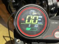
Guys I have been fighting these controllers for months they were working for a while then I unhooked a wire and connected it wrong and got an E10 error VICANTEC sent me new controllers and new throttle and it worked for a while.

I still never had the proper diagram to connect it properly bc it is dual motors and now I’m getting E10 error code again which is a communication receive error.

If someone can help me I will pay! I have been after this Chinese company to help me and it’s crazy how bad the service is!

Do the brake cables have to be connected? Bc I didn’t want them and when I disconnected they brake lights and blinkers I started getting 1/2 battery readings.

I really need to start all over.....I have a mess here lol I have blown my power wires XT60’s x2 lol

Help help Thx
 

Attachments

  • C883ED97-23E9-46EA-AB70-633586C91EFA.jpeg
    C883ED97-23E9-46EA-AB70-633586C91EFA.jpeg
    418.6 KB · Views: 1,380
  • 5E9AF78A-A394-4301-888B-4F57C57D81EB.jpeg
    5E9AF78A-A394-4301-888B-4F57C57D81EB.jpeg
    453.1 KB · Views: 1,369
  • 22E660ED-F282-4ABD-8785-9CCF71328F4B.jpeg
    22E660ED-F282-4ABD-8785-9CCF71328F4B.jpeg
    540.7 KB · Views: 1,381
  • 9DC69D3D-F802-4AAE-A06D-A03B7773D9E3.png
    9DC69D3D-F802-4AAE-A06D-A03B7773D9E3.png
    195 KB · Views: 1,390
Hello everyone and congratulations for this beautiful forum. :)
I have a problem with the brainpower controller, bought a 36V 250W kit, but it only has throttle. I wanted to get a new controller with the LCD S866 but I can't get it to work.
The motor with its controller works (both with the PAS and with the accelerator), but with the new controller it does not work. there is ERROR 07... I did self-learning, checked the phases, checked the motor hall signals, checked the impedance of the MOSFETs ... everything seems ok, but it doesn't work, the wheel turns very slowly without force, even with full throttle or with the PAS. I put a video ... Do you know where I can be wrong? Thanks


brainpow.JPG
ommm.JPG
https://www.youtube.com/watch?v=oTKGgq0ijW8
 
pavlik1 said:
Can someone help with the Chinese translation of the attached picture. The controller Above is the same
TB281BMh8smBKNjSZFsXXaXSVXa_!!140088562.jpg

Hello, I have a similar controller Model 800A-6T, coupled with the same Display, bought here https://www.aliexpress.com/item/1005003055890832.html. There is the translation of the wiring. I hope that can help you

I have a problem:
The display is broken. Where can I buy it a new one?
The seller of the whole kit doesn't have only the display.
There are other Display compatible with Xulinda controller?

Thank You very much to all
 
Hey guys for the question as to why the motor makes weird noise. The answer your looking for is Connect the intellegent sensor first turn ON the display the wheel will move slightly….here is the important part while the display is still on disconnect the intellegent sensor first before turning off the display then turn it back on! VOILAA will run smooth!!! Try it out.
 
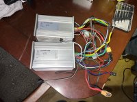
OK, so the first of the XLD controllers arrived (the smaller one, from Amazon: https://www.amazon.ca/gp/product/B07DQJJV46/ref=od_aui_detailpages00?ie=UTF8&psc=1).

Gotta say, for $40 (Canadian), it seems put together better than expected, though the bar was low. Upon seeing this thing in person, and revisiting this thread, it occurs to me that variants of this thing - at least units that seem to run with the same unique MCU - have been discussed on ES for some years. I haven't worked my way through all of the threads yet, but this is flavour I now have in hand. It doesn't have the hookup for the external LCD, so I'm not sure how radically different it is at its core.

View attachment 7

Wiring:


View attachment 6

PCB:

View attachment 5

View attachment 242328

View attachment 242332

After changing out a lot of the connectors for something I can actually attach to a bike (Andersons and JSTs), it did install painlessly. The auto-learn feature for the phase/hall wiring worked well (you connect together the green wires, power up the bike, and it starts spinning the wheel. If it's spinning the wrong way, you touch the throttle and it reverses - disconnect the green wires, and this setting is remembered). There is a speed connector on there that does the expected. There are three speed settings - leave the connector open, and the motor runs to the middle setting. Short black to grey, and the top speed is reduced. Short black to white, and you get 100%.

There is a pair of grey wires whose function is claimed to be "EBS". These come connected together out-of-the-box. Sure enough, if you apply the brake (I have it wired to the "brake low" input), the motor is slowed down to a complete stop. My suspicion is that this isn't actually doing any regen - it's just shorting the phase wires to get the braking effect. I won't be able to prove this until I try the controller out on a bike with a Cycle Analyst on it.

Now - there *is* the often found tie between the EBS (or regen, if true) function and LVC. This controller claims to be a "36/48V" unit, and to auto-detect its power source. When I have the controller connected to a 10S lithium pack (whose state of charge was at around 39V when I was testing), the EBS feature works as expected. If I connect my usual 12S pack (which was hot off the charger and running at 49.9V), the EBS feature DOES NOT work.

Studying the PCB, there is an interesting resistor array that appears to be in parallel with one of the resistors that form what I'm assuming is part of the voltage divider that is feeding the LVC measurement to the MCU.

View attachment 2

Any of these resistors can be jumpered to GND to change the balance of the voltage divider. It's interesting that the options go all the way up to 80V. The board is not populated with components that would allow you to even think about going there. The caps are 63V units, and these are the FETs that come with this thing:

View attachment 242336

Those are 68V parts.

For giggles, I jumpered the "60V" resistor in the LVC array, and now EBS (or regen, if true) works with the 12S pack. The bike won't run, however, with the 10S pack - evidently, the LVC *has* moved up, well above 39V - I need to go back at this with a variable power supply to determine what the real cut-off values are. At least, if none of them are satisfactory, there's a clean place on the board to play with different resistor values :).

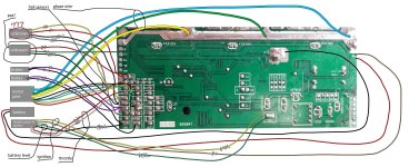
Anyways, I thought I toss this out there - the markings (and chip used) on this board seem to be very similar to the board posted earlier in the thread. I've mapped out where all of the coloured wires go, and what the do (though I have no idea how the "alarm" feature is used), so FWIW - this is the diagram:


The "power and electric lock" function is straightforward. The heavy red and black are your main battery power, and the orange wire is the "ignition" which provides battery power to the actual controller logic.

Phase and hall wires are standard, as well. There's a group of pads on the PCB - "5V", "U", "V", "W", and "GND" all together. These are the red, yellow, green, white, and black hall wires, respectively.

The EBS brake wires are both grey and, when jumpered together, turn on the braking (or regen, if true) capability - provided the LVC and power source are compatible. These are connected to pads labelled "DS" and "X" on the PCB

The "high potential brake" (it's purple) is an input signal that would be used if this controller were used on a scooter. You'd connect this to the same 12V signal that drives the bike's tail light. It goes to "SH" on the PCB and has the same effect as shorting the low potential brake.

The low "low potential" brake (the one most of us actually use) is a black and white, going to "GND" and "SL", respectively. When shorted, this switches off motor power and activates EBS.

The throttle ("handle accelerator", as diagrammed) is red, white, and black. Red goes to "+4.3V", black to "GND", and white to "SD" - the latter being the actual throttle signal.

The "gear switch" is the 3-speed control. Black goes to "GND", grey to "K1", and white to "K2". Left open, the motor runs at its "medium" speed. Short black to grey, and speed is reduced to "low". Short black to white and you get full speed.

The "reverse function" (brown and black, going "DC" and "GND", respectively) reverses the motor when shorted.

The "cruise function" (blue and black, going to "Q" and "GND", respectively) holds your current speed when shorted.

The "autometer signal" is interesting. It seems analogue (though probably just buffered PWM). The faster you go, the more voltage you read on this line. What's weird is that it hangs out of the controller, unprotected and uninsulated, but ramps up as high as 18V when the bike is at full throttle on a 39V pack. It's blue, and connected to "S+". I have no idea how I'd use this, though driving a regular analogue panel meter could be fun. :)

There are two connectors for an alarm function - which I have NO idea about.

Alarm power (red and black) goes to pads marked "PS+" and "GND".

Alarm signal is three wires - Grey goes to "A3", white goes to "W", and orange just brings back out full battery voltage (it's directly connected to the orange "ignition" wire).

Dunno if any of this is useful, but its the first time I've had my mitts on one of these "X806M" based controllers.

I'm dubious about the "sine wave" output of this thing. So far, the motor I'm playing with sounds exactly the same as it did with the older model Infineon job that was previously on there.
Would you be able to help me
 
Back
Top