EKartGo Project

Sheet dropped off, parts should get cut either tomorrow or early next week by this monster. Can't wait to get soldering on the nickel and getting this pack completed.
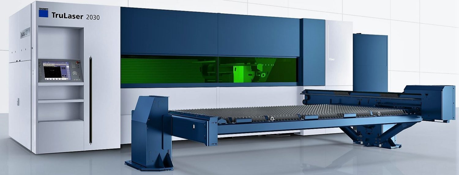
cropped-csm_TruLaser-2030-fiber-L72-product-picture_54d6068513_76f2902aac.jpg
 
Just picked up the parts - look good. I think the scaling between mm and decimal inches was a hair off, but nothing that it going to cause a problem. Now to get the MOT solder station completed, soldered, and then fire up the KWeld to attach them to the cells.

cut_buss_bars.jpg
 
Battery base and holder are complete, other than cutting out the upper right corner. Ice storm today, so that will have to wait a day or two.

IMG_20201027_121548sm.jpg

Now to get the nickel strips attached to the copper. Not going as easily as hoped. I'm going to try baking them together instead of MOT soldering.
 
Requested information and testing for the Peregrine 60 144v motor. Nix the heavy under-powered Motenergy motor series, I'll wait and make 2021 fun with this instead.
 
Planned episodes:

EP01: Intro - Done!
EP02: A Salt and Battery
EP03: BusBar Mania
EP04: Avoiding Wiring Spagetti
EP05: It's all about the BMS
EP06: Charge!
EP07: Merry Christmas
EP08: Batteries Included
EP09: Ground Control to Major Tom
EP10: Velocity Control and Cleanup
EP11: First Spin!
EP12: Up in Smoke
 
Episode 2: EKartGo Spreadsheet

This episode shows how to make use of the EKartGo Spreadsheet. Includes selecting a battery runtime, motor choice, and a controller choice to provide resulting battery solutions.

[youtube]xKfQeJxk5RA[/youtube]
 
Brilliant work! I can see you've put a lot of time, effort and passion into this project, the spreadsheet is especially helpful. Loved your video content on youtube as well
 
If you are using the spreadsheet with lower power motors and cylindrical cells, I would download a new copy. I improved it for these, as before it only used high C test results, which are not as valid for low power motors. This improvement uses the runtime to determine the continuous amperage from test results. I've also added a lower power motor and controller as well.

https://drive.google.com/file/d/17zbJZlLocxkfjNDHHixH1WDFVqIe6gAd/view?usp=sharing
 
hallkbrdz said:
https://drive.google.com/file/d/17zbJZlLocxkfjNDHHixH1WDFVqIe6gAd/view?usp=sharing
Pouch AMP20M1HD-A C-rate and max amps are not right in your table :)
Due of that also my 4kwh battery specs are wrong in your excel.
As I know AMP20M1HD-A has 15C or 300A.
 
nuxland said:
Pouch AMP20M1HD-A C-rate and max amps are not right in your table :)

Due of that also my 4kwh battery specs are wrong in your excel.
As I know AMP20M1HD-A has 15C or 300A.

Noted. I don't remember where I originally obtained those values. The site I referenced in the spreadsheet now shows it as:

"Continuous discharge rating: 10C(200A)"
"Nominal capacity: 20Ah"

So... I'll use your input since you actually have used them and have updated the file. :D

https://www.dhgate.com/product/100-genuine-usa-deep-cycle-lipo-battery-lifepo4/408192525.html#s1-0-1b;srp|1739443904
 
I finally have a useful method (still needs some refinement) to produce bus-bar nickel strip sandwiches for my battery!

Video to follow soon.

vlcsnap-2020-12-01-19h17m11s819_sm.jpg
 
That had too much flux on it, I want it all removed. I had added water-based flux, but the resin flux from the middle of the solder is what you see. Several posts suggested this, so I ordered some ethanol to dissolve the solder flux quickly.
 
I wonder if rather than using solder which can be time-consuming, opposed spot welding could be another choice?

Copper sandwiched between nickel could potentially work, as I know that spot welding copper to nickel alone is difficult to get right even with specialist equipment.

I'll do an experiment as I've never really tried this before.
 
Spot welding... been there, tried that. MAYBE that is possible with a high power spot welder, but defiantly not with a KWeld (it will just timeout at 200ms). The thick copper bus bar absorbs the heat energy too quickly.

Also using a MOT solder station does not work well. For me that was because of the wide surface area and differences in expansion rates. But it is great for any connector you want soldered. However, for large cable crimps I bought a hydraulic crimper and am using that instead.

So shake and bake it is... :D Although a fluxless solder might work better.
 
hallkbrdz said:
Spot welding... been there, tried that. MAYBE that is possible with a high power spot welder, but defiantly not with a KWeld (it will just timeout at 200ms). The thick copper bus bar absorbs the heat energy too quickly.

Also using a MOT solder station does not work well. For me that was because of the wide surface area and differences in expansion rates. But it is great for any connector you want soldered. However, for large cable crimps I bought a hydraulic crimper and am using that instead.

So shake and bake it is... :D Although a fluxless solder might work better.
Depends how thick your busbar needs to be really, as its all about cross sectional area, most tend to overshoot it with little benefit, and can actually be a hindrance in execution (no ability to spot weld)

With resistance welding there's a few tricks other than parallel welding which most people think is the only way, there's two other methods which don't require as much energy, step and opposed.

https://sunstonewelders.com/resources/choosing-welders/understanding-cd-micro-resistance-welding/

Got a question actually, whats the cross sectional area of your bus bar at its thinnest point? And what current are you hoping to push through it?
 
Using the correct units now...

For the 4x5 bars the square area is 44.7mm, larger than a 1 AWG wire. For the 2x10 bars the current flow is 50.19mm, larger than a 1 AWG wire. For the battery connection bars the square area for that narrow section is 55.27mm, larger than a 1/0 AWG wire (larger mainly to allow for connection losses).

In B&S 206 mode I anticipate about 42 Amps average, 47 peak.
In 100cc TAG mode I anticipate about 96 Amps average, 108 peak.

Of course full-out for a drag race to about 120 MPH - 350 amps!
 
I'm STILL waiting on the 3D printed parts to arrive, or even a confirmation email that they have shipped. However the strip copper from Georgia Copper showed up ahead of Christmas so I can get started on the connector strips.

I was hoping to make an upload a video with the new printed parts... but it appears it will be just a bit longer. In the mean time, I think I'll release what I have, which is the new design with a special spoof intro.

https://www.gacopper.com/022-CopperStrap.html
 
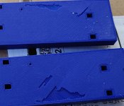
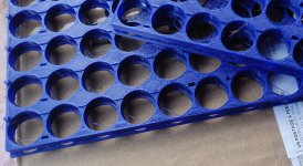
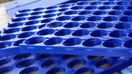
The good: The 3D printed parts showed up today

The bad: Some are unusable due to layer shifting and sticking to the printbed. Waiting for re-prints.

I should just buy a printer - but... I thought sending the job to someone who does it all the time would be better for the first crack at it. I'll have a video up this weekend, but for now here are a few pictures.

IMG_20210108_151831_sm.jpg
IMG_20210108_151811_sm.jpg
IMG_20210108_151848_sm.jpg
 
Back
Top