Electric kart

Hillhater said:
......But with my calculations and test (I tested 25kw gap in the same track and got 1,6Ah or 1,6kwh per lap) I would consume about 80Ah or 80kwh of energy......
???..i suspect you missed a decimal point out of your kWh figures > :wink: :bigthumb:
Yes, you are right. Corrected in the original post also.
160wh per lap and 8kwh per race :)
 
There was another amateur race series (not endurance jet) but sprint instead. 9 laps and i raced with rotax max and dd2.
Lipo battery handled very well. There was some problem with canbus data recording, it seems that tabled just lost connection to canbus in 3 races and i only got data when i raced with my lifepo4 battery. lipo battery data was only recorded when there was qualification, but i made only 6 laps there.
[youtube]lNk1CtsC0bQ[/youtube]
 
Did some analysis and comparing lipo and lifepo4 battery. Found one strange but logical thing. With lifepo4 battery motor temp was 8 degrees higher after the race. Even with lipo we raced 10 laps but with liepo4 only 9 laps.
LifePo4vsLiPoMotorTemp.jpg
Also with lifepo4 9 laps + 1 warmup and 1 cooldown lap took 19,2Ah
But with lipo 10 laps + 1 warmup and 1 cooldown lap took only 18,2Ah
Its because with lipo voltage drops less under load LifePo4vsLiPo.jpg
Motor requested torque was the same in both races 60% but with lipo power seems to be more even during the race, even voltage declines with usage.
LifePo4vsLiPoPower.jpg
Race 4 video is here
https://youtu.be/k01fZp9gK3Q
and Race 2 video here
https://youtu.be/DPWSidVa2Vw
I think i drove both races as hard as I was able to :)
 
That is amazing that voltage drop so positively affects motor temperature.
And when you look at this graph it is understandable why it is so.
There is less current to field weakening (the current that does not make torque but just heat) the blue one.
Motor current is around the same spot (orange one) and it should be, beause configuration and speeds are the same, only voltage sag is less :)
 

Attachments

  • LifePo4vsLiPoWeakening.jpg
    LifePo4vsLiPoWeakening.jpg
    120.5 KB · Views: 3,937
Took the kart to another track and let a professional driver race it, accelerator wire got stuck and so he could not get the best out of it, but his time were still around 2s better than my :twisted: .
His laps:
[youtube]rShP1MLI-p0[/youtube]
My laps:
[youtube]b_sFFfAPB5Y[/youtube]
Torque was tuned to 85% in both videos and it was a little to much for this track. In real race it needs to be tuned down to 65% or similar to be able to race 10 laps without motor temps going to high.
He used "profile 2" with press a button in finish stright to get more speed than 112km/h :) I only used it once.
And one lap is around 850m in length
 
nuxland said:
Got myself a iCharger 4010Duo to balance my repaired pack (even made two sets of charge and balance wires with crocodile endings).
wires.jpg
And as always did not read the manual at first :( (RTFM is a must next time) So connected both sideof the charger to same pack and caboom one side (right one) of charger was dead. Anyhow I then balanced the pack with one side. And a good thing is that iCharger also calculated IR-s.IR.jpg
PS! repaired also the charger afterwards, only 4x 15A fuses and one diod where burned away :)
diod.jpg
fuses.jpg

Hi, I have the same problem you had once. It seems like I blew 2 diodes and one row of fuses, but my charger is shorted now..
I hope that is because or the other blown diode, shorting the coil I believe.

Anyway, I have a problem finding the diodes. They are marked MT 83A. Do you know what you used?
 
I measured diod parameters from other side and used similar parameters random diod. My diod that I used was bigger and I used wires to solder it there.
PS! these chargers are delicate ones. The first one is tosted at the end as I inputed there 51V. Second one I also burned because disconnected wrongly two 12v lead acid batterys. And now I have a third one that is working fine right now :(
 
Thanks, so you didn't find a data sheet on the diodes? You just used what you saw on a multimeter when measuring?
How did you disconnect wrong, pulled the plug without stopping the charge first?

I split a 20s battery in 2x 10s still connected to the controller. I have fuses between, I usually just turn them off and let the controller discharge and turn itself off. This time I had turned off the controller already, so it was probably not discharged when I connected the charger.
 
Have already long time thinking of changing my kart frame to a better one. My current frame is from the year 2014 and was then bought used (I was rookie then and it was worn already from bottom).

So now this happened: BentRearShaft.jpg
Was my own fault and I do not know what I was thinking to get this edge of track.
Analyzing video it seems I did not turn enough left or ....
[youtube]I91KQdF9ST4[/youtube]

Anyhow I already have a new frame coming and old one are already striped from all the equipment :)
So no endurance this year but hope is that with the new frame lap times will be at least 1second better.
 
j bjork said:
That looks bad, but is it really damaged except for the rear axle?
It dosent really matter I guess, if you wanted another chassis anyway.
Front left spindle got damaged also. But it did not matter as I wanted to move to a new frame anyhow :)
As for the frame, it was old and I want to get better lap times, that was the real reason for change.
 

Attachments

  • LeftFrontDamaged.JPG
    LeftFrontDamaged.JPG
    79.1 KB · Views: 3,731
hallkbrdz said:
101C motor temperature shown. No issues with it getting that hot?
I have it configured that from 113 it will start to slowly cutback until 130 where power will be almoust zero :)
I have air push trough so magnet temperature should be lower as temperature is measured from windings and there is airgap between them and rotor. Also air i always cooling rotor also. So magnets should be always be less than 120 degrees.
 

Attachments

  • MotorTemperatureCutback.jpg
    MotorTemperatureCutback.jpg
    27.3 KB · Views: 3,714
Ahh, I see. I had assumed that Zero used Neodymium magnets which start to weaken at 80C and that the temperature probe reading would be somewhat close to what the rotor is seeing, especially for a SMPM instead of IPM motor.

That has been my max target as far as a motor / cooling system design goes. Sounds like I'm over conservative (as normal) and need to look into this some more since the max operating temp is oddly something many motor mfr's rarely put in the specs.

EDIT: I found this discussion and stand corrected (in a good way). Apparently most decent motors use N35SH grade magnets which have a spec maximum of 150C, with the only reference I could find for a ME1507 showing a 140C max. So the above sounds fine, and makes keeping the motor in an acceptable temperature range MUCH easier. :D No worries then.

https://endless-sphere.com/forums/viewtopic.php?f=30&t=87013&start=25
 
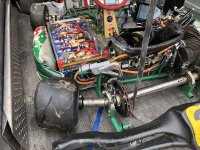
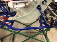
Out with the old
IMG_7200.jpg
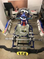
And in with the new
FromTop.jpg
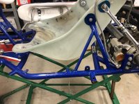
Also started to make room for battery base and cut away parts that are on the way :)
If battery side is completed then next thing to do is controller placement in front of the motor.
BTW I will install motor sprocket to driver side this time, then there is more room for my quad cooling fans.
 

Attachments

  • Before.jpg
    Before.jpg
    148.4 KB · Views: 3,611
  • After.jpg
    After.jpg
    147.2 KB · Views: 3,611
Nice!

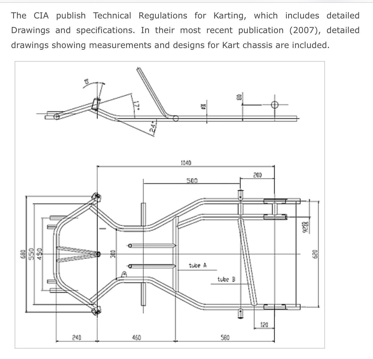
Curious - what is the spacing center to center between those sidepod posts? A couple of us are trying to determine if there is common standard for adult carts, or if it is mfr / model specific.
 
In this new Energy frame the distance is the same as my old tony frame. Will measure it tomorrow :)
 
CIA kart regulation specs are online.
And sites like this can be useful.. http://blog.kartbuilding.net/2007/07/12/free-technical-kart-drawings-fia/
nzyBVZ.jpg
 
Measured and from rear shaft center to rear sidepod center is 22 cm
And space betweeen sidepod centers is 50cm like in the photo.

Meanwhile cut correct length from aluminium tubing (outside 30cm and inside 24cm) made inside to 25cm for required lenght.
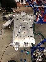
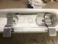
Also cut another tube between them and also new sidepod fixation from aluminium. Now need to weld these together.
Will use old aluminium fast fixation plate (just will make more holes to get it lighter)
 

Attachments

  • AluminiumTubingForBattery.jpg
    AluminiumTubingForBattery.jpg
    139.4 KB · Views: 3,479
  • SidePodFixations.jpg
    SidePodFixations.jpg
    92.1 KB · Views: 3,479
Hillhater - Thanks, looks like my battery support will bolt to mostly any frame then. :thumb:

Nuxland - Nice! I would have like to have made the support all aluminum, but metric tube supply here is - difficult. Oh well, maybe the next time.
 
Back
Top