Stress Testing 3.2V 100AH prismatic cells

vangogh

1 mW
Joined
Sep 13, 2020
Messages
15
Hi Everyone,

First post here. I know many of you are miles ahead of me, so I'm posting this humbly and hoping for some (kind) input. I have an old EET degree that I never really put to use, and I've forgotten more than I've learned. But I'm catching up quick lately on account of wanting to put a ~20kW LFP bank in my new 2020 awd high roof transit w/2" lift, bigger tires, etc. I plan to have a 250A 24V alternator.

I've got the plant director of a small lithium battery manufacturer in China sending me two 3.2V 100AH prismatic LiFePO4 cells so that I can stress test them. I'm mostly interested in how the cells perform at higher temperatures (40C-70C), with relatively low charge (0.33C) and discharge rates (0.5C, 03C, 0.2C, and 0.1C).

When the time comes and I order the larger battery bank, I'll have a 6kW sigineer inverter/charger, and the 250A 24V alternator + wakespeed regulator, but at the moment, I don't have the means to charge/discharge single cells, or at most the two 3.2V 100AH cells in series or parallel.

Any recommendations that don't break the bank, since I won't be reusing the test equipment very often, if at all?

I found a small ~$118 charge/discharge unit on Amazon that looks like it'll get ballpark 0.5C discharge rates (it's only 150W max), but I think it may only charge at 3.2V 5A. I'm asking the maker if the 22V 5A charge spec is the upper limit on each of those, but I think it is, so even though 22x5=110W, I can't instead do 110W/3.2V=34A or 0.34C, which would be perfect. I'm beginning to understand amp ratings are fixed on most low end variable dc power supplies. Here's the unit. Any thoughts?
https://smile.amazon.com/Digital-Battery-Capacity-Analyzer-Performance/dp/B08CF2ZYC7

For low budget discharging, I have another idea, but please tell me if this is nuts. I believe I can buy 4 x 100W 0.3Ohm wireround resistors, and put them in parallel, to get the resistance down to 0.075Ohm. At ballpark 3.5V fully charged (or maybe it'll be 3.65V?) I'm assuming 3.5/0.075Ohm=47A discharge current, which 4 x 100W resistors (400W) should be able to handle, right? 3.5x47A=~165W. Is a circuit like this too unstable and unpredictable?

If not, great. The resistors are only about $20 for 4 of them.

If it is a nutty idea doomed to failure, then I assume then I'll need a DC electronic load discharge device. The KP184 rated to 400W looks like it could work. But $175-$200 is a lot for a device I'll only use a few times. I guess I could ebay it afterwards. https://smile.amazon.com/Single-Channel-Electronic-Battery-Capacity/dp/B07Z4Q9JWV/

For low budget charging, I'm really stuck. I keep finding 10A max variable dc power supplies, or that first charge/discharge unit that I believe may only be 5A, nowhere near the 33A/0.33C charge rate I'd like to test. Any ideas on how to charge a 3.2-3.65V 100AH LFP cell at 0.33C/33A without spending a fortune? It's crazy how 12V 500A power supplies are a dime a dozen, but trying to get 100A at 3.5V requires diamonds and gold bars. For a minute I thought I could use the same resistors to voltage divide my way into using a 12V power supply, but I'm beginning to realize that's just too dangerous and likely to damage the cells before I get to the real reason I'm doing all of this -- high temperature stress testing.

Assuming I eventually solve the charge/discharge part without spending $1400 on a used Cadex C7400ER-C (ain't gonna happen), then comes the more dangerous part: stress testing the cells while still gathering measurements without injuring myself or others. I'm a bit of a dukes-of-hazard billy-the-kid type, so I'll figure it out or die trying, but I'd much rather get some guidance from others who know more than I do before I say screw it and start blowing sh!t up.

My first thought was build a metal box and set it in the sun, which just a month ago would have hit 40-60C easily. But it's already getting down to 30C ambient in September, so I'll be lucky to hit 40C in the box.

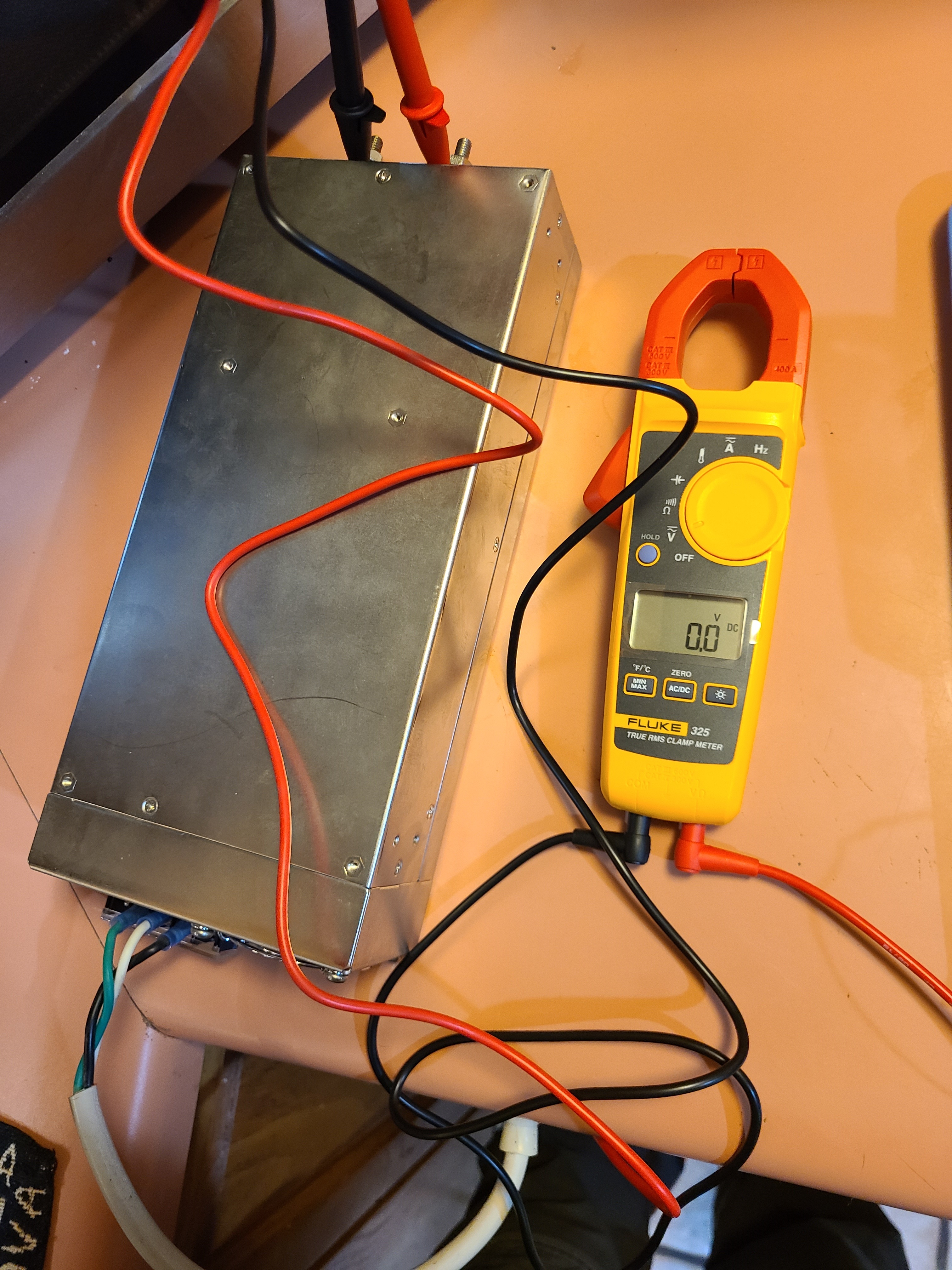
So how about using my portable $100 walmart radiant "oil" heater I use in the winter. It's fully passive, no glowing coils, just a quiet and slow but steady radiating heater. I could set a metal box on top of it with some ceramic fiber under it to isolate it a bit, turn it on low, measure the temp in the box, figure out how much venting will get the box at 40C, or 50C, etc, depending on the test, then put the battery in the box with the discharge unit next to it but down on the ground shielded from the heater. Take measurements with my fluke 32 at set time intervals (cover my skin and wear a helmet?).

It's ghetto science, but hey, I want the data. Will these cells expand, leak electrolyte, smoke/fire, etc at 0.33C charge and 0.5C discharge at 40C, 50C, 60C, 70C? I don't plan to overcharge or over-discharge, because that's not planned usage, but if my van's a/c system, with active fan venting backup fails, and the big 20kW bank I buy is sitting in the van in the sun while I'm off backpacking for 5 days on a 40C ambient day with 60-70C inside the van, I want to know what these cells will do. Granted they'll be new, and any data I gather won't apply to the same cells in 3-5 years, but at least I'll have a starting point for the upper/lower thresholds that isn't based on some battery manufacturer's statements, but based on real world observations and testing. I was born with "I'll believe it when I see it" stamped on my forehead.

Please help. I'll buy you a 6-pack someday!

Cheers.
 
If you're just testing one cell at a time, at. 5c that's up to 50amps @3.2v. Most dischargers won't go to 50 amps even if they are 150w
I would go and buy a roll of nichrome wire and make your own wire wound resistor. You'll only need a few meters. Wrap it around something heat proof and/or non conductive ceramic, wood or the likes. Say 6 strands at the right length ~1mt. Start with a bit more and cut it down (or join it at shorter points) to get the R you want. Dump it in a bucket of water. Voila several thousand watts of variable discharge capability for a few bucks.
I do it lots to test ebike batteries (sans the water)-makes a nice warm bench top heater.
Other ideas are halogen light, hairdryer/heater/stove elements but these are harder to adjust.
Capture data with an inline watt meter
 
There are two tests / benchmarks that a new set of cells need on arrival before commissioning, all such tests best performed on one cell at a time.

1. ESIR aka resistance

2. actual capacity in Ah, via a CC load test, for LFP from 3.6V down to say 2.99Vpc, at 0.25C is a goid rate, takes less than 4hrs per cell.

Both of these factors will deteriorate, roughly in parallel, as the cells wear from cycling and/or calendar age

Each time the benchmarks are run to gauge SoH, precision requires using the same gear, cells being at the same temperature, etc

So, that's just normal testing. The "stress" aspect from your post only involve the elevated temperature.

Those C-rates are all just optimal for longevity, the only difference you will find between them is a slightly higher Ah capacity at lower current rates, IMO a waste of time.

Hot ambient conditions will greatly reduce longevity, both to calendar life just stored, and to cycle count longevity.

However you will only see that impact at the back end, and depending on all the other care factors relevant to longevity, the bank will likely last over a decade, depending on your definition of EoL.

Unless of course that little company makes crap cells, which is very likely, compared to top makers like Winston, CALB, GBS, Sinopoly, CATL and A123 (now Lithium Werks / Valence / Super B)

And a key QA factor is consistency, how well matched the cells are in those two factors to each other. Of course you won' t know that until the full set arrives. Order spares!

vangogh said:
https://smile.amazon.com/Digital-Battery-Capacity-Analyzer-Performance/dp/B08CF2ZYC7
ZKE makes decent units, has dozens of models http://zketech.m.icoc.in

see also https://endless-sphere.com/forums/viewtopic.php?p=1503313#p1503313


I have a bunch of raw notes collected from a variety of forums, will send via PM.

After browsing from those, please post short specific questions, I might get around to parsing that whole wall o' text in the next few days, but also may not get a round Tuit.
 
If 30A charging is close enough then you can't beat an iCharger X6. I've had my older version model for almost 10 years and it's been an invaluable tool for working with lithium batteries. If running at the 30A limit I'd put a little fan blowing some extra air its way to ensure it's not under heat stress.
 
kdog: thank you. This is perfect for inexpensive high C rate discharge tests, which I'll probably do towards the end of my stress testing if the cells have held up. The nichrome DIY resistor in a bucket of water sounds like a quick way to reach 1C 2C 5C discharge rates etc no problem, which could also help test the output needed when the van/RV's dual AGM engine batteries die someday, and I need to use the lithium bank for starter cranking. It would just be pulse discharging, but still, maybe I could combine this with other lower power DC load dischargers to create a real-world scenario: pulse high C, steady low C, rest/no discharge cycle. Rinse and repeat.

John61ct: Man, you really came through here, and my ability to do meaningful testing has been significantly improved. Thank you! I have a lot to learn about measuring the internal resistance on new cells, and how to conduct a quality upfront capacity test. Also, the ZKE units for discharging are much cheaper than the options I was considering, and provide a way to capture more data than my resistor route, especially for low C (normal use) discharge rates. I have a lot to read with those invaluable notes you sent.

This is what troubles me the most, and I had a vague sense of this already, but "Hot ambient conditions will greatly reduce longevity...however you will only see that impact at the back end."

I guess all I can hope for now is to do as many cycles as possible and to crank the heat up until a problem appears, then try to do some regression calculations to backtrack estimate to what lower temperature that same problem might appear after multiple years/cycle counts.

John in CR: fantastic! Thank you sir. This is now my top choice for charging. 0.3C is perfect. It's probably even closer to real-world summer alternator output charging conditions than my 0.33C.

Cheers.
 
ECPC has pro's and con's. Not saying scammer, but a small outfit, basically a garage one-man show.

Carl is technically proficient, but his ability to spend time with you greatly diminished once the sale is made.

I suggest dealing in minimum practical small lots per order, so if you claim warranty he can afford to honor it, he has had to welch out in the past.

Very likely your "plant director" is not, and that company is likely just a trader, not any one company being the manufacturer.

See Wayne Giles people for resistance details. IMO not at all "the" metric

secondary to capacity tests, especially for low-C rate applications.


vangogh said:
"Hot ambient conditions will greatly reduce longevity...however you will only see that impact at the back end."

I guess all I can hope for now is to do as many cycles as possible and to crank the heat up until a problem appears, then try to do some regression calculations to backtrack estimate to what lower temperature that same problem might appear after multiple years/cycle counts.
Why do you need to try to estimate the impact?

You are nearly guaranteed to miss the ballpark by as much as 2000 cycles and 5years.

If "guaranteed" longevity is that important (not possible) then just go with those known-good makers I listed.

Best of all likely to be A123 pouches, assembled yourself. But finished prismatics from any of the others can last for decades, maybe 8-10,000 cycles if coddled

that heat factor yes reducing lifespan, but not so much as to destroy the value equation.

Not possible to locate in a cooler spot?

Or put in a cooling loop as the EV guys do.

Or just figure per-year cost based on five rather than eight years, and be happily surprised when it reaches ten.

 
BTW you don't get all this for free!

Please pay it forward, give back to the community by posting your "winnowing" process notes, do not wait for "final" determinations but write up every valuable snippet gleaned as you go.

Ideally start a "CC load testing for actual capacity" thread, refactor and organize and flesh out expand on the notes I sent you to add value to them.

Also start a separate thread on what you gather on standardised ESIR testing, let me know when you're ready I have a separate scratch doc for that topic as well.
 
kdog said:
If you're just testing one cell at a time, at. 5c that's up to 50amps @3.2v. Most dischargers won't go to ...
...a roll of nichrome wire and make your

rap it around something heat proof and/or non conductive ceramic, wood or the likes. Say 6 strands at the right length ~1mt. atteries (sans the water)-makes a nice warm bench top heater.


Other ideas are halogen light, hairdryer/heater/stove elements but these are harder to adjust.
Capture data with an inline watt meter

Did you just recommend wrapping Nicrome around wood, then energizing the circuit with DC hibh voltage? Then say " I do it lots to test ebike batteries (sans the water)-makes a nice wa" ?!?!?!?!?!

Ok then.
 
Nah re read. 3.2v (not exactly high), and dumped in a bucket of water would keep it cool enough to use a lump of wood as a substrate.
I'm sure the OP can figure out how to be safe.
My ebike battery discharge station is an air cooled coil... hence 'makes a nice bench top heater'.
Who said anything about high voltages?
 
need a total resistance of about 1.0 ohms to a maximum of 1.4 ohms, with the highest possible heat loadability. 1000W or more would be good.

the aluminum bodied wirewounds are the most robust, keywords:

Aluminum Wirewound Braking Resistor OR Resistance

or this guy: https://www.digikey.com/product-detail/en/1879455-1/A105577-ND/2367759


or cheap automotive 1157 taillight bulbs are ~50¢ each and can dissipate 25+ watts without issue. Ten of these provides 250 watts of available power dissipation

The larger iChargers from Junsi like 4010 Duo work well to keep the Current precisely Constant


john61ct said:
Very likely your "plant director" is not, and that company is likely just a trader, not any one company being the manufacturer.

Very good info, thank you and all the other respondents. I am definitely skeptical of anything anyone says who is selling any product, so I'm with you on the raised eyebrow. After many exchanged emails, and discussions, my sense is that he's legitimate (whatever that's worth). Carl also can't say enough about him, and said he toured the facility last year. Small, but producing a high quality product was his evaluation. And he claims he's known the guy for a decade. I don't know if I can trust Carl either, but at least it's a second confirmation/validation of my own interactions.

But you are probably right, and I may well look into building my own pack using one of those reputable cells. The nice thing about these larger assembled packs is they include a case that's already setup to fit them snugly and offer IP66, they have a BMS and all the wiring, and they have a 2500W laser busbar press that I wouldn't have access to in a DIY build. You get all of that for a reasonable price, about the equivalent price of buying a batch of individual cells with no case, bms, busbars, etc, so presumably the volume purchase (16 cells per pack) is what affords that difference. But maybe it's lower quality lithium, could well be. And I would like to have my own pack designed precisely for my own application, with CAN communication, quality temperature sensors, ideal cooling/vibration, etc.

I asked the guy about a pouch pack but he said they disperse heat better but they don't endure vibration as well, and I'll be using this as an off-road van/RV, so vibration is already a high concern. I figure I'll need to do what I can to isolate the packs with a rubber base or some kind of shock absorbing platform, but the reality is these packs are going to be shaken and rattled a fair degree, so prismatic seemed like the best bet.

Liquid cooling is a possibility, but I worry about the system complexity, leaks, etc, and it may be overkill since I'll already need to pay for an a/c unit for livability, so I'm hoping to make that the primary cooling method, and active venting as a backup if the a/c fails and temps rise. But if both of those systems fail, as they will eventually, I want to know what will happen at say 70-80C with 0.5C discharge. Will the new cells just suffer a shortened lifespan (I can live with that) or will they leak electrolyte and catch fire. I'd like to see these cells withstand that -- with my own eyes -- then know that 5 years from now the risk will be higher, but at least to begin with I can rest easy knowing that an a/c and active fan failure on a 50C day in Arizona parked in the sun with 70C-80C internal vehicle temperatures while I'm off backpacking for a week isn't going to result in a catastrophic incident.

Thank you again everyone. I'm learning a ton from these responses.

Cheers.
 
Hi Folks,

I went to ebay and bought a used MEAN WELL SP-750-24 SERVO STEPPER MOTOR Switching Power Supply DC 24V 31.3A 750W to go along with my iCharger X6.

I plugged the PSU in, and no LED, no voltage output. Started an ebay return, seller just refunded no return required, but I still wanted to be sure there isn't some common issue with these. I tried adjusting the pot down to its lowest setting, but nothing. I only hear a faint click sound when I unplug it. I verified that no breaker was tripped, outlet is fine. My 12V power supply plugged into same outlet powers right up.

Got my two 3.7v 100AH LFP battery samples sent over from the chinese manufacturer. The plant director sent them air freight at his expense, and so that was a nearly $600+ gesture on his behalf. He clearly believes in his product and is happy to have it tested to prove is statements.

Thanks for your help.

Mark

sjkgN5S.jpg
 
john61ct said:
I was not able to find a link to that Chinese vendor?

Or is that proprietary info between you and ECPC Carl?

Vendor can be deduced via a bit of sleuthing, but at the moment I'm not writing it out publicly (can do in a message though) because the vendor has been very generous, including sending via air freight two 100AH sample cells at their cost, and has agreed to completely rework their BMS to suit my needs (more output pins with custom alert triggers that occur before a BMS cutoff so I can disconnect charger and loads). I'm also doing translation for them as well now, and they should have the new BMS completed and finished testing in late December, so once I purchase and receive the four 5kWh units, I'll be in the opposite mode of helping to publicize them assuming everything checks out. They use a fully automated cell matching system that has best results if the cells are all from the same run, so I'm planning to just buy the full bank at once, even though I know there's a bit more risk there. I've just really gotten to know the guy, and Carl swears by him, so I think he's legitimate.

john61ct said:
At only a 5 year lifespan, under 2000 cycles they'll barely be broken in, you'll likely get what you paid for them selling secondhand :cool:

Very difficult to get precise SoC% levels, just define setpoints via voltage + current (C-rate) throughout.

I like that! Recouping in 5 years and buying the best available at that times sounds like music to my ears.

Starting to understand voltage for a given c-rate is the way to think. Thanks for that. Vendor provided me with guidance:
tYZerdF.png


john61ct said:
Going past 3.5V, especially if holding CV for any time, you really are not adding much if any useful stored energy, just creating heat against resistance.

When testing that statement, remove excess "surface charge" voltage with a tiny load, then allow a few hours' isolation - resting voltage at 3.33-3.35V really is basically the best definition of SoC 100% Full.

By comparative cap testing between that and the result of say

hold 3.6V until current tapers down to 0.05C (or maybe 0.02C)

I'd be very surprised if you found more than 5% difference.

Will do on testing 3.6 vs. 3.5 for capacity. It's just slow now because I'm keeping both cells together as 2p for now to ensure they behave similarly before I start the real 1s stress tests on 1, and use the other as control. Interestingly vendor had stated "charge to c/20", so your 0.05C is spot on. With a 200AH total (2p) I had set it to stop at 10A (c/20 or 0.05C), and after completion, it dropped back down to 3.357 when I last checked (about 20 minutes after charging finished). The device claimed about 160AH had been added, although I know you said ignore capacity side Ah measures. Still good to see since it would align with them being at ballpark 20-30% SOC storage before I began. It's cold at night and the fan is loud so I'm running these in the garage. Will resume tomorrow daytime for 1st full discharge at a gentle C/20 (10A) down to 3.095 for estimated 5% SoC per that table, or maybe even just 3.0 to see what else I can squeeze out of it for the sake of capacity testing, then recharge to 3.5, and repeat (probably day after).

john61ct said:
Does your use case need every mAh of cap utilization?

Only sometimes. I will occasionally be off-grid for long periods of time with only 31 gallons of gas or less (extend range tank at near full). Expanding the capacity utilization will help reduce charging time (high-idling vehicle for 2nd alternator), so more time off grid is possible. Gas is also consumed by a gas-fired heater.

john61ct said:
CC-only charging, "stop at X volts" is very easy to implement, and will give a precisely repeatable result if current is always the same.

This I don't understand. If I charge with CC, won't the battery's voltage spike up fairly quickly. It seemed like my iCharger went into CV mode almost right away and spent 8+ hours charging in CV. Could I have done differently with prolonged CC and still achieved a charged pack that wasn't damaged?

Cheers.
 
That use case, you do not need every mAh of cap utilization. Much better to size the bank a bit higher and relax, or just design the system so you can recharge a bit earlier.

Get solar going or carry a quiet little inverter genset to feed your AC charger

nominal 1000W will carry 30+A up to 40A with a slow start unit

rather than running your truck engine just to charge, that's crazy expensive, not just fuel but wear & tear.

Remember, this is **not lead**! in normal cycling getting to / sitting at Full is not the goal, and is often harmful, something to avoid!

vangogh said:
Vendor provided me with guidance:
tYZerdF.png
Interesting!

But build up your own table yourself for the rates / setpoints you choose.

obviously the variance from true resting voltage goes the opposite way charging vs discharge.


> I'm keeping both cells together as 2p for now to ensure they behave similarly

By definition, so long as they are connected, just creates a single cell barring one completely failing.


> vendor had stated "charge to c/20", so your 0.05C is spot on

Vendor just gained some cred :cool:


> after completion, it dropped back down to 3.357 when I last checked (about 20 minutes after charging finished).

Like I said. Might drop some more, some units 72hrs for real precision.

Any time you see much higher, pull like 0.1Ah out to dissipate surface charge, you'll see that likely represents close as you need to ever get to Full.

A 20-hr rate 0.05C is the lead bank cap testing standard, but way slower than usual for Lithium

except when a vendor is trying to inflate the Ah rating. :cool:

If they are anything like CATL/CALB/Winston/GBS, going from "max Full" say 3.6V taper to 0.01C

down to 2.5V if that is the (Danger do not go near in regular usage) data sheet minimum

at a 0.05 discharge rate truly precise & accurate CC dummy load - verify with a calibrated ammeter

you should get **well over** the nameplate rated Ah.

Not saying it's a big red flag if you don't, but I've got from 5-10% over from those top makers above, or else the sales channel was dodgy, price too good to be true.

As I said, the key is consistency, a given batch being well matched. Also checking ESIR, even with a low C-rate use case where absolute numbers don't matter, just consistency.

ESIR also a good benchmark to supplement capacity SoH% to track wear level from ageing, cycle lifespan, catching "unanticipated issues" impending EoL.

> Will resume tomorrow daytime for 1st full discharge at a gentle C/20 (10A) down to 3.095 for estimated 5% SoC per that table, or maybe even just 3.0

Once satisfied verifying the vendor QA,

just pick a roundish number at each end and stick to it. Arbitrary is OK so long as apples to apples.


john61ct said:
CC-only charging, "stop at X volts" is very easy to implement, and will give a precisely repeatable result if current is always the same.

> This I don't understand.

If you charge at a fast rate, say 0.5C caring about longevity, assuming warm ambients

you will hit 3.45V at an earlier SoC%, so no harm in bumping the "stop at" setpoint a bit higher.

It is when the C-rate gets down to say 0.2C or even lower, that you get closer and closer to "maximum Full" before reaching the setpoint, thus proper coddling means lowering it!

Below 0.05C , you can't even tell where you are in the curve anymore, entirely possible to harmfully overcharge at 3.40V letting it just keep going forever.

In practice only comes up with small solar relative to bank size, or poor insolation conditions, but as an extreme example.

Solution is counting coulombs in the way up and using that to stop-charge, not a great situation!


> went into CV mode almost right away and spent 8+ hours charging in CV.

What C-rate?

If the setpoint was low, and the bank kept absorbing a high current, maybe that did no "damage" (i.e. lost lifetime cycles off the back end, NP for you.)

At a "normal" say 0.2-0.4 C-rate, 3.6V setpoint, caring about longevity, it would be normal to only inflict say 10-30min of CV, the amps rate should be dropping darn sharply.

The key takeaway here is, voltage on its own is meaningless. The current rate needs to also be known for anything to be said about SoC%.

Just realize also, SoC% is never really "known" directly, only guessed at, and most coulomb counters are pretty innaccurate.

Using very precise CC regulation (again, verified, calibrated gear!) coupled with a precise **timer** is much more accurate.

> Could I have done differently with prolonged CC and still achieved a charged pack that wasn't damaged?

There is no way to "prolong CC" other than dropping the C-rate, the SoC% point where the transition takes place is not a function of any regulation circuitry but "negotiated" between the batt and charger at the level of chemistry and physics.

Good news is, that doesn't matter, no reason to do so!

There are myriad profiles (V&A combinations) that all get to the **exact** same SoC% target.

I only brought up the "stop at" method because no matter the charge source type,

an adjustable LVC will prevent overcharging (cut off the source's input, not output, because load dump),

so no need to spend lots extra on specialized gear.

Again, getting all the way to Full is not the goal, best avoided, unless loads are running, to pull SoC% back down soonish
 
john61ct said:
That use case, you do not need every mAh of cap utilization. Get solar going or carry a quiet little inverter genset to feed your AC charger

Believe me, I've been down this road. It's one area I do know about. Efficiency is the name of the game in off-grid a/c. I've studied every possible solution and the only one that makes sense for my requirements is a 240V 42 SEER Carrier mini-split (most efficient a/c in the world, even considering the 12% inverter loss). Powering that unit to run on batteries for 2-3 days is the challenge. 1000W is really high. The Carrier when maintaining a stable climate can get down to 250-350W, with 12% loss factored in, more like 300-400W.

No generators for me, already looked into that. They're bulky and loud (yes the new ones are better but not under heavy load), and they need gas. My vehicle can generate as much or more power from under the hood (so no bulky unit taking up space) just by SEIC high-idling with a 250A 24V second alternator. That uses very little gas (based on real world tests). Yes, some engine wear and tear, but changing oil at 2k miles is doable when idling for recharge, and many others have idled for many years and seen only minimal issues that resulted in reasonable cleaning or repair costs (usually valves, some emissions systems replacements; on a Transit it's cheap to fix, on a Sprinter, it's easily $6k just for DPF/emissions system fix).

Minimizing idling cycles is the reason for the large 20kW bank, so that helps reduce wear on engine and 2nd alternator while more importantly extending the range of time I can be out there (31 gallon extended range tank will help). Already built the space to house the battery bank, pretty much certain I'm going this route, just nailing down the source of the lithium and trying to keep cost low, hence the conservative 5 year horizon, which may well prove accurate considering the 120-170F temps the batteries could experience in the summer months when I'm off hiking (although plan is currently to have the a/c auto-trigger to keep it down to 80F when I'm away, but plans fail), and 0-30F in the winter, same thing (plans fail) with primary solution to use heat pump in Carrier unit to keep van interior up to 40-50F when I'm away, higher when I'm there, and of course battery warmer pads

john61ct said:
obviously the variance from true resting voltage goes the opposite way charging vs discharge.

This is part of the phenomenon I was unaware of, both for charging and discharging. I'm now beginning to understand that C rates determine the voltage plateau you'll reach, but after time the battery will return to a different level. What's alarming to learn (thank you) is that low C rates can let you over or undercharge a battery without any way to detect where you're at in the curve. How do BMS units handle that? How does the iCharger know what to do? I'm really curious how the physics of charging works, and the technological steps. I thought CC was like 30-40% of the time, then CV, for a relatively low C rate like 0.15C, which is what I was using yesterday to charge a 200AH bank: 30A nominal, but I never saw it hit that high and was in CV right away at 26...21-22...and on down to 10A (C/20 or 0.05C).

Was happy to find cells at exactly 3.35 this morning when I began discharging. Unfortunately only at 9A (iCharger limit). I can up the unit's limit a bit to max 50W, but it's already started so I'll leave it. But I sure hope 9A (0.045C) isn't dangerous and the unit knows how to handle that. I set it to stop at 3.01V but may have to do it in two runs since it gets too cold and night. I'll see where it's at by 10pm tonight. Any thoughts here?

Interestingly, 9A * 3.2V * 8 (2p pairs per battery) * 4 (batteries) = 921W, which is actually far more than my average load will be. Most of the time I'll be pulling 350-450W average, but 24 hours a day, non-stop, so only a day or two before a recharge cycle on a 20kWh bank with ~16kWh useable.

john61ct said:
If they are anything like...you should get **well over** the nameplate rated Ah.

Good to know! Thanks.

john61ct said:
Also checking ESIR, even with a low C-rate use case where absolute numbers don't matter, just consistency.

The iCharger showed a "Lr" for Line Resistance (wiring + 1s2p) at the start of discharging of 11 megaohms, if I'm reading that right. Has show 11.6 and currently showing 11.3. What should it be? I don't have anything other than the battery terminals wired to the iCharger (one from each, and both cells wired parallel).

john61ct said:
If you charge at a fast rate, say 0.5C caring about longevity, assuming warm ambients you will hit 3.45V at an earlier SoC%, so no harm in bumping the "stop at" setpoint a bit higher. It is when the C-rate gets down to say 0.2C or even lower, that you get closer and closer to "maximum Full" before reaching the setpoint, thus proper coddling means lowering it! Below 0.05C , you can't even tell where you are in the curve anymore, entirely possible to harmfully overcharge at 3.40V letting it just keep going forever.

I sure hope the iCharger knew was it was doing. I charged at 0.15C/30A yesterday, stopping at 0.05C/10A. Thanks for making me aware. No trickle charging. I have no plans for anything other than maybe a small bit of solar because to use it you have to park in the sun, thus making a/c work much harder and negating the value proposition. Plus cleaning the panels on a 12 foot van roof = not fun.

john61ct said:
At a "normal" say 0.2-0.4 C-rate, 3.6V setpoint, caring about longevity, it would be normal to only inflict say 10-30min of CV, the amps rate should be dropping darn sharply.

Yikes. Why was mine at CV for so long? I tried the LiFe profile initially and it did the same thing. I edited a copy of it and just set the "stop at" and capacity. I assumed the iCharger knew what it was doing. Wrong?

john61ct said:
Using very precise CC regulation (again, verified, calibrated gear!) coupled with a precise **timer** is much more accurate.

I had hoped the iCharger was that. I did see a calibration function though and have not done it yet.

john61ct said:
an adjustable LVC will prevent overcharging (cut off the source's input, not output, because load dump),

Did you mean HVC?

Thanks again John!

Cheers.
 
Okay, I got some data, and learned some things.

With a slow ~0.05C discharge rate, I got 192.5Ah at a somewhat cold 10-17C. I had hoped for more since the discharge rate was so low, but I didn't go up to 3.65V and down to 2.5V, I only did 3.6 to 3.01, so that's probably part of it. I also learned that without balance leads the iCharger tends to jump into CV too fast, so I ordered the jts-xh connector to wire them up. It may also help with measuring internal resistance. I'll update after it arrives and I get it hooked up.

I get about 4mOhm Lr (line resistance, so includes wiring) when I measure each cell individually without the balance leads. The manufacturer said it should be 0.5mOhm, so I'm way off. Manufacturer says can't trust most low-cost devices for internal resistance measurement. They say use the DCIR method (e.g. 10 seconds 10A, 10 seconds 100A, measure voltage at end of each, divide voltage difference by current difference = internal resistance). I'm working on getting a way to do an 80-100A discharge so I can do that test.

I'm planning to get 6 100W 0.2 Ohm resistors, wire them in parallel, which should let me do 96A discharge (not with iCharger obviously). Still trying to figure out how to do the ~10A part then quickly switch to the ~100A resistor set. I'm thinking one 0.3 Ohm resistor, which at 3.2V should get me 10.67A, but then I need a simple way to manually switch over to the big resister set. Maybe buy a switch that can handle 100A or come up with some other manual method.

Cheers.
 
Okay, balance leads were definitely the answer. Charging now holds at 30A for much longer, and IR measures a tiny 0.4mOhm. Manufacturer said expect 0.5-0.6, so I'm happy with the sample cells. Next I plan a full 3.65V charge to 2.5V discharge to measure AH (at 0.1C 20celsius). I'm hoping to see at or over 100AH per cell.

I'd really like to wire both cells in parallel while charging and have balance leads on both cells, but I don't know if the iCharger will understand what to do with that. It seems like it's only designed for 1s 2s 3s...6s. I'll give it a try and see.

Cheers.
 
vangogh said:
I'd really like to wire both cells in parallel while charging and have balance leads on both cells
If you mean just two cells wired in parallel at 1S, 3.2Vnom

That is just a higher Ah capacity single cell electrically.

Could put a hundred together, still just on big huge cell.

All "self balancing" just one big circuit all at the exact same voltage.

 
vangogh said:
I got 192.5Ah at a somewhat cold 10-17C. I had hoped for more since the discharge rate was so low, but I didn't go up to 3.65V and down to 2.5V, I only did 3.6 to 3.01, so that's probably part of it
Not probably, certainly. Close enough I'd say, 4% is likely within your measurement error anyway.
 
vangogh said:
.
john61ct said:
an adjustable LVC will prevent overcharging (cut off the source's input, not output, because load dump),

Did you mean HVC?
Whoops yes good catch!

Wow aircon off storage? no genset ever? idling alt for high amp charging?

super ambitious good luck.

But having the aircon autostart the FF burning when you're not there, that's flat-out nutso, not wishing you luck on that one, pure evil :cool:


> low C rates can let you over or undercharge a battery without any way to detect where you're at in the curve. How do BMS units handle that?

They don't, no BMS will beat a thoughtful human paying attention.

Maybe jerry rig timer + coulomb counting, but I wouldn't trust it!

Same with chargers, do not give their "intelligence" that much credit

A CC-stage current rate lower than what the tapering end current is such a bizarre non-occuring edge case fuggedaboudit.

Just do CC-only profile as I said, charge-to the setpoint and stop, done.

> I thought CC was like 30-40% of the time, then CV, for a relatively low C rate like 0.15C

The lower the C-rate the less CV, you're already at a very high SoC% when you hit the transition, very low delta of "V drop back down" after stopping.


> was in CV right away at 26...21-22...and on down to 10A (C/20 or 0.05C)

Means cell not much depleted.

> I sure hope 9A (0.045C) isn't dangerous and the unit knows how to handle that.

How could too **low** a discharge rate be dangerous????

Don't fuss too much about temperature, lab-quality results would require a lab. . .

Abiut resistance, just read this again:
john61ct said:
Also checking ESIR, even with a low C-rate use case where absolute numbers don't matter, just consistency.

Using a different instrument, or different temps or SoC or C-rate will give wildly different results.

Design your benchmarks, and run them every say 500 cycles to see how they're aging.

Do not trust any device's built in V&A readings.

Always verify with your own known good, regularly calibrated independent standalone measuring instruments.

So long as **you** know what you're doing, with custom adjustable gear, you keep adjusting until it is doing what **you** intend. or close enough.
 
john61ct said:
But having the aircon autostart the FF burning when you're not there, that's flat-out nutso, not wishing you luck on that one, pure evil :cool:

I honestly don't mean to harm the environment with that setup, and I may do some solar, but it's just not practical to power a/c loads with it considering the limited roof space and high cost of deployable panel systems (maintenance too, cleaning, etc). Every house and business that has a/c is drawing far more total power and generating far more waste (trash, sewage, water waste) than my tiny house on wheels ever will, and they pull their power from utilities which often burn fossil fuels (even today, especially when gasoline prices are low). The very small total amount of emissions I create to just barely maintain a safe operating temperature for the lithium while I'm away from the vehicle and in an off-grid situation is inconsequential compared with a 16,000 foot homeowner who is heating/cooling non-stop as well. And since I eat only an occasional steak or burger, when you factor in the average high-consumption beef eater and they're causing more ozone damage than I ever will.

john61ct said:
> low C rates can let you over or undercharge a battery without any way to detect where you're at in the curve

> How could too **low** a discharge rate be dangerous????

It's these two statements that got me mixed up. I thought a low C rate could potentially let you overcharge or over discharge because you don't know where you're at in the SOC curve. In any event, the balance leads solved the issue. The iCharger now reads the IR and the true voltage correctly, so it stays in CC much longer now.

Thanks again for all your time and energy spent helping me get up to speed. I still have a lot to learn, but I'm getting there. Now the challenge is figuring out my inverter. I'm looking at a Schneider Electric Conext 4024, but not sure which of the dozens of accessories I really need. I also want solar expandability, so possibly a 60 150 MPTT from them. The Conext has a nice feature of including an autotransformer, so if I encounter only 120V (versus the 240V my a/c runs on) it will step up the 120 to 240 for me. It'll even supplement a low power 120V input from the batteries for startup loads (hybrid).

Cheers.
 
I thought you needed the aircon for your own comfort.

Believe me, not worth setting it up just to extend LFP lifespan a little!

They can take it, you said you only needed five years anyway!

If you do need really aircon (aren't you mobile?) then you will be well served to size your units to work off a Honda EU2200i, I'd bet you'll end up getting a genset along those lines

Power on demand without burning up your propulsion engine. . .

But start out filling the roof space with solar, shoot for 2+kW if possible.

vangogh said:
john61ct said:
> low C rates can let you over or undercharge a battery without any way to detect where you're at in the curve

> How could too **low** a discharge rate be dangerous????

It's these two statements that got me mixed up. I thought a low C rate could potentially let you overcharge or over discharge because you don't know where you're at in the SOC curve

As I (thought I) said, if your C-rate starts off lower than your desired endAmps rate

that just means you can't use a charge profile where stop-charge is based on endAmps!

Use CC-only, e.g. "charge **to** 3.43Vpc and stop"

Or measure Ah out, then put back those Ah*1.1 or whatever your CEF turns out to be.

Personally I would not trust any coulomb counter's accuracy that much.


Gotcha. Good stuff. Thank you sir!

I do need a/c for my own comfort while in the vehicle, but the issue raised was having the vehicle auto start to run the a/c when away from the vehicle, hence the counter-argument. I just worry about 170F+ temps with lithium sitting there baking, and I would like this bank to last 10 years if possible, it's just that I prefer low expectations as a baseline. Hard to go wrong with that approach.

I think I may be able to get enough solar to power the ultra-efficient 42 SEER. I found a guy who has been running his minisplit on his RV for years almost entirely off solar.

Cheers.
 
Small very well insulated space

1800+ panel Wattage to get say 1500 for the direct running aircon, just that load, need to park in the sun on purpose

then you need energy for recharging your bank to cover all your other loads

And if you want to run the aircon between say 4pm and 10am, good luck doing so off storage from the bank.

Yes in theory "can be done" but crazy pricey and rarely practical IRL.

Better set up to be able to do so from gensets, then keep building out your solar to see if you can cut your runtime a fuel costs by say over half.
 
Back
Top