LeftCoastNurd
100 W
- Joined
- Oct 22, 2019
- Messages
- 127
Waynemarlow said:The only time we have seen motor current draw problems was both times a battery fault. Turned out to be a poor weld on some of the cells which was restricting the current, as soon as you stopped or at rest the voltage would recover back to the norm.
that would cause a drastic voltage drop of the battery under current load?
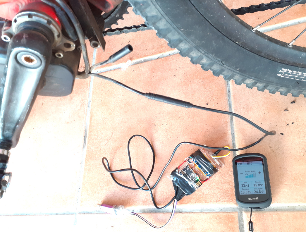
k, next time, I'll setup one of the displays to show batt voltage and current along with motor current and human watts
Swannking said:May be the torque sensor is failing. I would go into the technical menu which shows the value of the sensor while u are riding and try to see what’s going on with the value when that happens. I highly recommend for u to do the sensor calibration. I used a cheap luggage scale.
isn't the 'human power' display directly related to the torque sensor (after being run through the calibration table) times the cadence ? 'human power' was reading fine, like hovering around 150 or 200 watts or whatever while pedaling briskly, while motor power was 0, then suddenly motor power jumps back to whatever it should be.
casainho said:If the human power is well calculated (you can test it with motor disabled at assist level 0), motor should not give different currents / power than what you expect. I can´t imagine why that would happen. There no reports of such issue.
I hope you can figure out the issue...
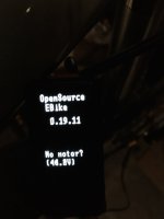
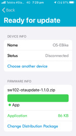
And don´t forget to update to latest firmware version.
I need to figure out why my ST-Link didn't work when I tried setting it up.
")