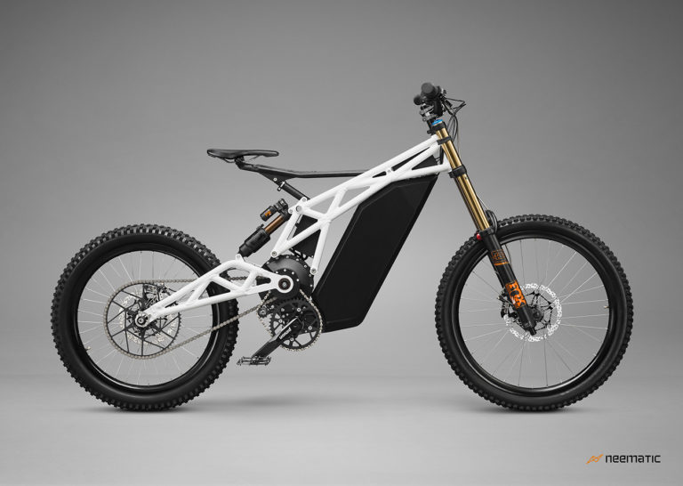
Incorporating a Pinion C1.9XR in the LMX Frame
I initially thought this would be major, but decided to have a look anyway
")
Of course my model of the Frame is approximate as it is deducted from a series of pictures, and I do not know the details of the swing arm and motor to validate interference down there. But using a 3D model of the gearbox, it actually looks like the gearbox fits inside the two frame plates, which means we could attach it by running long screws and spacers across both plates.
If that does not interfere with any of the motor and swing arm (which I don’t have any info to model), it would mean only cutting a part of the bottom left side, welding some extension plates at the bottom and on the right side to receive the mounting holes, and probably reinforcing the frame by welding a junction plate between the two sides and above the gearbox mounts.
Using the existing bottom bracket tube and a template one could precisely mark the mounting holes and cutting profile, and would just need to manufacture spacer tubes to put between the sides and the gearbox, as well as between the gearbox mounts. Minimum welding would be involved, and precision could be fairly easy to achieve.
Using the Pinion Fat Bike Spider and cranks, we could actually match the existing chain line.
Just a dream, but I thought it was interesting
Of course as I mentioned before, then comes the issue of the torque sensor...
There use to be one called the BEAMTS that fits on the top of the pedaling chain but it does not seem to be available any longer. May be a rear dropout one like the TMM4 would work, I also heard of Chain Ring Torque sensors, but do not know if they can be fitted on any system.
Anyway, here are the CAD drawings
Online LMX folder
https://1drv.ms/u/s!At3vMAQjaOZLknFVeh7KzoAENbW3?e=G6scG1