Nucular electronics - complete kit for ev!

People with ASI BAC controllers seem to have nearly as many problems getting programming help as with Sevcon.

Merlin said:
you cannot tell me they have 3 factories producing their shit
Likely the don't own any factory, pretty much a last-century concept.

Outsourcing arrangements can indeed change from one month to the next.

And doing enough "assembling" in a local customer market, in order to qualify for a Made in (not China) sticker, would be good marketing.

 
Mostly correct but there are some caveats. Mainly, this is not a free lunch as it may seem, there is a price to pay.

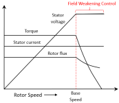
A motor speed is limited by the applied max voltage, current, and the counteracting backEMF. You can spin a motor up to a point where BackEMF is equal to the applied power, that's the base speed of a motor that can be calculated from the motor's KV and applied max voltage. Beyond this point, to spin a motor faster, you need reduce the counteraction of the backEMF and it's accomplished by reducing the rotor flux linkage that is setting the d-axis stator current to a negative value. In the base speed region, the motor's torque is linear which translates into a vehicle's agility/maneuverability (you can accelerate, pass quickly, etc - all those things we love EVs for). Above the base speed RPMs, the torque drops rapidly as seen on the graph below. This is not to say there is no application for operating a motor in the FW region but you have to account for a significant torque drop. On a vehicle that would translate to loss of that agility.

xxmcb_fwc_charac.png

Source:
https://jp.mathworks.com/help/mcb/gs/field-weakening-control-mtpa-pmsm.html

Other things to remember are increased risks of the whole system's catastrophic failure when operating in the FW region. A controller faulting or even resetting with motor operating within the base speed would be uneventful most of the time. If the same happens while the motor spins above the base speed, you can expect huge jolts of currents and voltage via the controller and back into the battery. This would easily exceeds the mosfets rating limits and the battery can turn into a spectacular fireworks. Ideally, additional protection circuits need to be designed to account for these possibilities to keep the system safe. More complexity means further diminishing returns on the FW used in such applications.

You also want to to take into account the motor construction. Most motors used on ebikes, such as hub motors, etc. are SPM motors where field weakening will perform poorly or will not work at all. With those motors, you are more often than not better off winding/gearing for the max base speed and/or designing the battery for the voltage to meet your speed requirements.

FW starts to make more sense with IPM motors and in conjunction with the MTPA where the actual magic/free lunch is happening such as a good bump in efficiency/torque through addition of the reluctance torque into the mix.

Darren2018 said:
PITMIX said:
FW is the weakening of the magnetic field of the motor at high speed. It only increases the rotational speed when maximum rpm is reached. The magnetic field being lower, the motor turns faster because it turns freely without resistance, but this implies a drop in torque. It is the same as increasing the voltage for maximum speed but it does not allow to have as much acceleration and power at low revs. This is how I understand it.

Finally as explanation that I can understand! :lol:

Now I would just like to see it on a graph like a before and after but that is for another thread.
 
Powervelocity.com said:
Other things to remember are increased risks of the whole system's catastrophic failure when operating in the FW region. A controller faulting or even resetting with motor operating within the base speed would be uneventful most of the time.
In my understanding, in the Nuculars implementation of field weakening, the BEMF is not allowed to increase above the voltage limitations of the controller (i.e. max allowable motor speed is basically the peak unloaded speed). So there will be no catastrophic failure.

Oh, and along those lines:
BAC failures: 1,738,583 (or thereabouts)
Nucular failures: 0 (actually if I recall correctly, I think there was 1 failure reported, but the user admitted fault).
Let that sink in.

Powervelocity.com said:
You also want to to take into account the motor construction. Most motors used on ebikes, such as hub motors, etc. are SPM motors where field weakening will perform poorly or will not work at all.
Out of all the people using the Nucular controller, I haven't heard reports of problems. Mine works perfectly fine on a MXUS 3k4T. "Poorly or not at all" is just not true.

Powervelocity.com said:
Above the base speed RPMs, the torque drops rapidly as seen on the graph below.
That graph is not indicative of a real ebike setup at all. A torque curve will never be flat for the full range of rpm and then suddenly drop off. There are so many other limiting factors (controller current limit, battery current limit, back EMF vs battery voltage), so torque is usually ramping down almost immediately at low rpm (well below the "base speed"). Without field weakening, top speed is never equal to unloaded speed of the motor (that would be physically impossible), so field weakening can be applied at a much lower rpm than shown in your graph, and torque can be increased over a relatively wide and useable rpm, well below the unloaded speed.

Powervelocity.com said:
but you have to account for a significant torque drop. On a vehicle that would translate to loss of that agility.
Again, the torque curve is not flat all the way through the speed range like you depicted, so saying that field weakening will have significantly reduced torque ("loss of agility") is a complete exaggeration, and you're not comparing real world conditions.

IMO, I think just about your entire post is disingenuous.
 
Powervelocity.com said:
Don't take it too personal. The above stated is a common knowledge and is well documented in many sources like in the one linked. FW is a great technique but it needs to be put in a larger context for optimal use. Such as the type of the motor, safety/reliability/efficiency considerations, etc.
Just calling it like I see it.

I'm guessing the powervelocity controllers don't have field weakening?
 
They do. Currently in testing. And MTPA as well. And it's open source.

serious_sam said:
Powervelocity.com said:
Don't take it too personal. The above stated is a common knowledge and is well documented in many sources like in the one linked. FW is a great technique but it needs to be put in a larger context for optimal use. Such as the type of the motor, safety/reliability/efficiency considerations, etc.
Just calling it like I see it.

I'm guessing the powervelocity controllers don't have field weakening?
 
Powervelocity.com said:
Other things to remember are increased risks of the whole system's catastrophic failure when operating in the FW region.
To battery may happen some inrush current but whole FW limited to safe mosfet voltage, nothing bad will happen with NUC

Nucular failures: 0
Well thats not true, we had some issues with v1 6F and first assembled 24F, sometimes wire issues happen. But not so much, so it is not bugging us.
I would be aware of subvoton, im gettign so many messages from my new users about "just plugged and it died", dont waste a money on those
 
VasiliSk said:
Powervelocity.com said:
Other things to remember are increased risks of the whole system's catastrophic failure when operating in the FW region.
To battery may happen some inrush current but whole FW limited to safe mosfet voltage, nothing bad will happen with NUC
Thanks for the confirmation.
 
Is it possible to know the wattage or rated current on Nucular?
 
Powervelocity.com said:
They do. Currently in testing. And MTPA as well. And it's open source.

serious_sam said:
Powervelocity.com said:
Don't take it too personal. The above stated is a common knowledge and is well documented in many sources like in the one linked. FW is a great technique but it needs to be put in a larger context for optimal use. Such as the type of the motor, safety/reliability/efficiency considerations, etc.
Just calling it like I see it.

I'm guessing the powervelocity controllers don't have field weakening?

I have owned 2 different Powervelocity Controller's over the years and loved them. Getting a hold of the company for customer support has been an issue for me.
 
I've been messing with my nuc 6Fet with an LMX motor for a few months now. A while back I was trying to troubleshoot an issue where the motor seems to lose sync and stutter when unloaded in FOC mode. Many people suggested that the hall sensors might be causing the problem. I finally got around to checking them with the oscilloscope. This video is with the motor at 3700rpm in sensorless mode. The signal looks pretty clean to me but maybe somebody else might see something I don't. So what do you all think? Is this enough to rule out the hall sensors as defective or inadequate?
AUDIO IS HORRIBLE! TURN DOWN YOUR VOLUME OR MUTE IT! SORRY.
[youtube]koY_Ig18x_k[/youtube]
 
In "Debug information" you can see the signal from the sensors when your engine is running in " Hall imput" line. 001- 011- 010-110-100-101-111.
When we say faulty sensor it means no signal from one or more dead sensors. There if you have the signal from all your sensors it means that they are correct.
I am preparing the translation of a little video that I had made some time ago, it shows this.
Here you can choose English in the video settings, by clicking on the 3 small dots at the bottom right of the video.
[youtube]WcT_5Ha-RkM[/youtube]
 
Just have a couple of questions on hooking up a Bake Light through port P1.
I have the brake switch connected to IO8 on the display and I set port P1 to Spec. and PWM to Stop-Light.
Should I be able to see, using port state, that I have a output signal on P1 when I use the brakes?
Also do I have to access P1 from the controller or can I assign it to an spare output on the Display?

thanks Eddie
 
Strange thing is happening, If I run the Heinzmann PM 100 motor With the 24 F Nucular in sensorless mode it gives more power then it gives in FOC mode. Battery is 52 volt. Max phase current in FOC mode is 357. In sensorles it is 220. Max power is 7218 kw in FOC and 9023 kw in sensorless. How can this be?
 
The power is not calculated with the phase current but with the battery current.
I think you also made a mistake in the units.
7218kw it's a Dragster engine.
In FOC mode the speed is higher and the operation is optimized in sensorless mode it is all or nothing, so the power is brutal but the RPMs lower at maximum speed.
 
Should be Watt and not kw. :wink: It is not a dragster but a gagas trailbike. In sensormode it is indeed more tame then in sensorless but how can I make it more punchy because I need power coming from zero rpm. The FOC is smoot from zero rpm but I need more instant power with this kind of sport.
 
Can someone please clarify something for me... the first post says the nuclear 24F controller is rated for 20 kW max... yet it has an output current of 300 amps at a maximum voltage of 90 V.

Doesn't that mean its rated for 27 kW max?
 
mbgjt1 said:
first post says the nuclear 24F controller is rated for 20 kW max... yet it has an output current of 300 amps at a maximum voltage of 90 V.

Doesn't that mean its rated for 27 kW max?

Most such ratings are "whichever limit you hit first applies"

So at lower rpm amps is your controlling limit.

At higher voltages (speeds) then watts power becomes the controlling limit.

Really, no matter what, internally generated motor heating up overrides everything.
 
john61ct said:
mbgjt1 said:
first post says the nuclear 24F controller is rated for 20 kW max... yet it has an output current of 300 amps at a maximum voltage of 90 V.

Doesn't that mean its rated for 27 kW max?

Most such ratings are "whichever limit you hit first applies"

So at lower rpm amps is your controlling limit.

At higher voltages (speeds) then watts power becomes the controlling limit.

Really, no matter what, internally generated motor heating up overrides everything.

Oh I see

Oh well can't complain 20kw is still a heck of a lot on a 50kg bike!
 
If I remember correct it says about 20kw, I guess it is just to give people a number.
There is no 20kw limit. With the "right" setup you can probably reach 30kw, maybe more.

And 300A is not the limit, you can set the controller to 400A. But you can only set the battery for 350A discharge, but there is a boost where I think you can get the missing 50A. I dont remember exactly, it is some time since I messed with it. There might be some changes in recent updates too.
 
I installed my new 24F in my Sur-Ron to get it running again (the oem controller died.) Having a great time so far! However, The control comes on w/ the battery breaker and not the key. Is that normal? Any way to change it?

An interesting observation. I can ride it around w/ just the breaker on (as 5V throttle power comes from the controller) but I don't have regen braking because the 12V supply for those switches comes from the 12V converter controlled by the key.
 
IMG_20200610_083940.jpg
 
Thank you! This was alluded to in a response on the Sur-Ron thread overnight and I missed that post before posting in this thread. (I could swear I hit refresh this morning and didn't see anything new :oops: )

I have to say the control was pretty easy to set up and get going overall. Very pleased w/ the experience so far!
 
Back
Top