tenten8401
1 mW
- Joined
- Aug 22, 2020
- Messages
- 16
caesareor said:Hello guys,
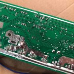
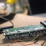
I'm new here. I compiled and flashed the firmware on a KT36/48SVPRD-HRD01 controller. I get no error at compiling (with proven setting: THR-PAS,KT36-48svpr,12s,26inch,Q128h + Diagnostics), the hex file is created just fine, I flashed it with the STVP. I get the message that the program memory was written and checked successfully.
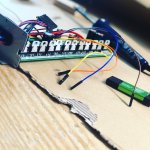
However when I power it (36V battery) and try to run it with the throttle (I don't have PAS yet because the parts are not installed on the bike) nothing happens. I connected a HM-10 bluetooth module to the LCD pins. All that I am getting on the terminal app is this character� when I short the blue and red wires of the LCD.
The controller/motor combination was working fine with the factory firmware (I checked it even after I soldered programing pins)
Any ideas about what I should try to troubleshoot it?
Did you try adjusting the under voltage setting? It may think the battery is too low