TSDZ2 EBike wireless standard (like Specialized Turbo Levo) - OpenSource

rananna said:
casainho said:
the remote could be detected by the Garmin Edge but the detection of click for page change was too slow and was missing most of the times...
That is very strange. I do not see any noticiable delay on the two garmin edge devices I have or with the garmin simulator. I certainly do not see missed page turns either. Is it a communication issue caused by distance from the board?
Another thought.
Did you pair the remote to ant lev when you tested the ant ctrl communication with the edge display?
As discussed in the configuration docs I wrote, if ant lev is not active, it must be disabled for ant ctrl to work on its own.
 
@casainho,
Some good news on the Nordic Dongle.
I have been studying the schematic and the power specs for the Nordic dongle.
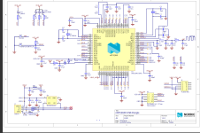
The VBUS pin (5V) is tied to VDDH of the SOC which is connected to the initial DC-DC converter to get 3.3V for VDD OUT
The VDD OUT pin is tied to VDD of the SOC.
As you can see from the schematic, the SB2 simply shorts VDDH to the VDD pins of the SOC.

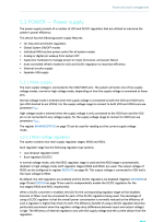
Looking at the specs, shorting VDD to VDDH also shorts out the initial 5V-3.3V DC-DC converter.
see:

So, for the remote control, to get the lowest power consumption, we can simply apply the coin cell battery at the VDD OUT pin of the dongle and connect the VDD OUT and VBUS pins together to disable the initial DC-DC converter. There is no need to ask the user to connect SB2, as connecting the board pins will achieve the same effect. Btw, connecting 3V to VDD OUT will also eliminate the mass_erase UICR voltage issue that prevents re-programming. This problem now goes away.

For the wireless controller, we can connect 5V to VBUS as usual.
I have tested this and it works great!
 

Attachments

  • dongle.png
    dongle.png
    509.4 KB · Views: 545
  • power.png
    power.png
    171.7 KB · Views: 545
@Casainho,
What was your thinking in removing the button timer in the bootloader?

The way you implemeted the button now in your suggested code changes is to always enter dfu mode on button release if the button was pressed during a reset.
Previously I implemented a 10s delay that only entered dfu if the 10s was up. If the button was released before the 10s it would go back to the app. You have a rtc timer that will unblock the _WFE and continue, but a button release will also unblock it and immediately enter dfu.
I thought we wanted the 10s timer to avoid accidentally triggering dfu by pressing a button to wake up the board?
 
rananna said:
@Casainho,
What was your thinking in removing the button timer in the bootloader?

The way you implemeted the button now in your suggested code changes is to always enter dfu mode on button release if the button was pressed during a reset.
Previously I implemented a 10s delay that only entered dfu if the 10s was up. If the button was released before the 10s it would go back to the app. You have a rtc timer that will unblock the _WFE and continue, but a button release will also unblock it and immediately enter dfu.
I thought we wanted the 10s timer to avoid accidentally triggering dfu by pressing a button to wake up the board?
I just corrected the code for test the simultaneous 4 buttons or RESET button at the timeout.

There are only 2 interrupts that will wakeup from WFE: button release interrupts and RTC 10 seconds timeout. Only the RTC 10 seconds timeout sets the flag g_start_bootloader = true; and only if the simultaneous 4 buttons are pressed or RESET button.

The current code is this one:
Code:
static void rtc_handler(nrf_drv_rtc_int_type_t int_type)
{
  if (int_type == NRF_DRV_RTC_INT_COMPARE0)
  {
    if (((read_pin(PLUS__PIN) == 0) &&
        (read_pin(MINUS__PIN) == 0) &&
        (read_pin(ENTER__PIN) == 0) &&
        (read_pin(STANDBY__PIN) == 0)) ||
        (read_pin(BUTTON_1) == 0))
    {
      g_start_bootloader = true;
    }
  }
}

I tested the bootloader and everything seems to work as expected (sorry, I have no LEDs on this board nor the BUTTON_1 - can you test this?).

Also, can you please keep pin definitions for both boards? Although we document only for one board, for other developers like me is important to be able to use the other boards.

And about the remote firmware, previously I was using an older version. But the latest version, although it flashes correctly with the bootloader, I do not see it working at all. Also flashing directly I do not see nothing happening (with correct ANT keys). Anyway, I am to much tired by now. Maybe you can try the remote firmware.
 
casainho said:
There are only 2 interrupts that will wakeup from WFE: button release interrupts and RTC 10 seconds timeout. Only the RTC 10 seconds timeout sets the flag g_start_bootloader = true; and only if the simultaneous 4 buttons are pressed or RESET button.
Ok, I see. This seems good.
I will test and let you know.
 
casainho said:
And about the remote firmware, previously I was using an older version. But the latest version, although it flashes correctly with the bootloader, I do not see it working at all. Also flashing directly I do not see nothing happening (with correct ANT keys). Anyway, I am to much tired by now. Maybe you can try the remote firmware.
I will look at this also.
 
casainho said:
Also, can you please keep pin definitions for both boards? Although we document only for one board, for other developers like me is important to be able to use the other boards.
I noticed you changed pins.h to delete the pin definitions for both boards.
I just restored it.
The defines are, of course, in the makefile.
Code:
[
// NRF52840 MDK Dongle
#if defined(BOARD_CUSTOM) && defined(NRF52840_MDK_USB_DONGLE)
                       
typedef enum {
    PLUS__PIN  = 5,
    MINUS__PIN  = 6,
    ENTER__PIN = 7,
    STANDBY__PIN = 8,
    BOOTLOADER__PIN = 18,
    BUTTON_PIN_ELEMENTS = 5 // must be updated when added or removed an element
} button_pins_t;
#endif
// NRF52840 NORDIC Dongle
#if defined(BOARD_PCA10059)
                       
typedef enum {
    PLUS__PIN  = 13,
    MINUS__PIN  = 15,
    ENTER__PIN = 17,
    STANDBY__PIN = 20,
    BOOTLOADER__PIN= 19,
    BUTTON_PIN_ELEMENTS = 5 // must be updated when added or removed an element
} button_pins_t;
#endif
/code]
 
casainho said:
beemac said:
casainho said:
They have a lot of contact with users and they may have important feedback for the project as also they may be interested to sell the board and so would give a big boost / success to the project.

If we were going for a more capable board - then i think the DC-DC converter is one thing. Would also be fantastic there's a way to provide an interface to allow flashing of firmware to all components on the ebike from the app. I need to learn about st-link - is it totally proprietary or can you use an SPI interface for instance...

Box would need to be mounted near the motor (or inside with external antenna) or have a long wire that taps into the speed sensor but being able to spec up a reliable cable harness into the wireless box that you can then use to flash all the firmware and do the wireless stuff too would really lower the barriers to adoption.
We can learn a lot with ESP32-TSDZ2 project: https://github.com/TSDZ2-ESP32/TSDZ2-ESP32-Wiki/wiki
It does program the motor firmware wireless (by the mobile app) while the board is connected only on the display connector.
It is also for mount inside the motor with the advantage that temperature sensor connects directly to this board and so throttle connection is always available.

I wounder if we can implement wireless throttle just like we plan to do with the wireless brake sensor. The wireless board is very small and so it will also be the box. I think will be much easier to install the box outside.

Agree about the ESP32 project - today I received three TSDZ2-ESP32 boards from pcbway that I ordered before I spotted this project - and since I run 860c and 1.1 firmware I'm not sure I'll use them. So even more annoying I had to pay duty because when I ordered they had a special on free dhl intl delivery... no option for epacket which is usually free of customs charges and I wasn't in a hurry.. Anyway - I stray off topic...

I've looked at the schematic for the ESP32 project and I think I'll re-use the DC converter circuit - and also similar level shifters for our board - unless people think that's total overkill I think it's a better than just the resistors if we want a reliable solution...

I now think that right-sizing the DC converter on the board is better than having a larger external one to cover all eventualities. Any USB sockets should have their own DC converter that's only active if the socket is being used - that way people don't have a large DC converter running at low efficiency most of the time...

I was also going to add fuses for the higher voltage DC connections - vbatt/esdz2_vin etc. as fuses are cheap and may protect the board from a short.

About standardising on the nordic blue - it's going to be easy once we have a v1.0 board to create versions to accommodate the maker board, mdk etc. by changing the pin arrangements. That keeps everyone happy who wants to use a board with whatever module they bought in anticipation.

Would still be good to hear from others who have the power circuit working correctly... I'm thinking that it might be useful to have the initial basic board for testing whilst we work on the other features... so once I've had a few positive confirmations about the power circuit being good (and so it's just me being a useless solderer!) then I can get a few basic boards made up for testing...
 
casainho said:
beemac said:
Box would need to be mounted near the motor (or inside with external antenna) or have a long wire that taps into the speed sensor but being able to spec up a reliable cable harness into the wireless box that you can then use to flash all the firmware and do the wireless stuff too would really lower the barriers to adoption.
We can learn a lot with ESP32-TSDZ2 project: https://github.com/TSDZ2-ESP32/TSDZ2-ESP32-Wiki/wiki
It does program the motor firmware wireless (by the mobile app) while the board is connected only on the display connector.

It's a step forward - but for both the board and the controller initial flash you still need to get down and dirty with an FT232 and STLINK adapter and run some pretty un-user-friendly bits of software... I think we could perhaps integrate an SPI on our board (FT232 would be simplest - but possibly not the cheapest) then that could be used to provide the flashing capability for the initial board firmware. Sounds like using the built-in nrf52840 USB port as a reliable initial flash is out of the question from what's been said about private keys and bootloaders - and would also be nordic blue specific. Once we have control of the 52840 we could potentially use IO pins as SPI to flash the motor firmware via a speed sensor cable tap.

I know it adds a cost - but most of the people i've spoken to about how good the oss firmware is - and who are keen cyclists and like 'tech', who would be ok with the mechanical and electrical installation but say 'ooh not sure I'd be able to do that' when I tell them they'd need to splice cables to do firmware upgrades to get the best performance out of it... so if we can make that initial step easier all the better.

edit: ok - splice cables isn't necessary if you buy the right cables - so maybe a good cable set and better flashing software would remove the need to include hardware on the board that's only used once or occasionally. Having said that I had to reflash my motor controller today as it seemed to die for no reason - error brakes etc. even with none attached - so having it onboard might not be a bad thing.
 
casainho said:
We can learn a lot with ESP32-TSDZ2 project: https://github.com/TSDZ2-ESP32/TSDZ2-ESP32-Wiki/wiki

Another thing I liked about the ESP32 is the tx/rx passthrough so you could use the usual physical display too. That to me seems useful e.g. if your phone broke for whatever reason you could plug in an 860c and carry on...

Best would be passthrough so you could use both at once but I assume that would require additional software functionality (does the protocol implement a bus or is it point-point?) - or at the most basic I could add extra tx/rx connections to the board with a physical switch to allow bypassing the wireless board as the 'display'. So we could have a socket on the dongle where you could plug in the usual display if required.

I think my initial thoughts of a $5 board are long gone.... no reason we can't have a basic and deluxe board :)
 
beemac said:
Would still be good to hear from others who have the power circuit working correctly... I'm thinking that it might be useful to have the initial basic board for testing whilst we work on the other features... so once I've had a few positive confirmations about the power circuit being good (and so it's just me being a useless solderer!) then I can get a few basic boards made up for testing...
We have the bootloader tested and finished!! We also have the mobile app mostly finished. Now our focus should be on the TSDZ2 wireless board firmware that is already 80% done and on the wireless remote that ANT+ LEV and ANT+ Controls are not working simultaneous.

May plan is to get the wireless remote firmware working so I can change assist level and I want to see the value changing on the mobile app, so, I will be able to change assist level simultaneous on the mobile app and on the wireless remote. Then I can finally install on my EBike and so I will test the circuit I have, as I will make a new board to install on my EBike and that will work as furhter testing of the current circuit.

beemac said:
Another thing I liked about the ESP32 is the tx/rx passthrough so you could use the usual physical display too. That to me seems useful e.g. if your phone broke for whatever reason you could plug in an 860c and carry on...

Best would be passthrough so you could use both at once but I assume that would require additional software functionality (does the protocol implement a bus or is it point-point?) - or at the most basic I could add extra tx/rx connections to the board with a physical switch to allow bypassing the wireless board as the 'display'. So we could have a socket on the dongle where you could plug in the usual display if required.
As you say, will be need more software developments. Who would want more work to do?? And seems you are duplicating, since the wireless board will connect to the TSDZ2 display connector, if you want to exchange for the 860C display, you just unconnected one and connect then connect the other.
 
@rananna,

About the current remote firmware not being able to control both ANT+ Controls and ANT+ LEV, being the ANT+ LEV implemented on the TSDZ2 wireless board, is not possible to use only the ANT+ Controls both to control the TSDZ2 wireless board and the Garmin Edge page change?? Would be like the wireless remote broadcasting the various buttons press over ANT+ Controls and the Edge reacts only to the page change and TSDZ2 wireless board would reacts to the rest of the buttons press. Do you think this would be possible?
 
casainho said:
@rananna,

About the current remote firmware not being able to control both ANT+ Controls and ANT+ LEV, being the ANT+ LEV implemented on the TSDZ2 wireless board, is not possible to use only the ANT+ Controls both to control the TSDZ2 wireless board and the Garmin Edge page change?? Would be like the wireless remote broadcasting the various buttons press over ANT+ Controls and the Edge reacts only to the page change and TSDZ2 wireless board would reacts to the rest of the buttons press. Do you think this would be possible?
I think there is some confusion over the configuration options for the remote. Let me try to clear it up. There are the 3 user case scenarios:

1. User has an ANT LEV bike + edge bike computer.
The remote works very well in this situation. It controls both devices well. If you turn off the edge computer (second ant channel 1) it continues to control the ebike well. ( Unlike 3 below)
There are no issues with either the ebike or edge computer with this configuration.
2 user has ONLY an ant lev ebike alone.
The remote controls the ebike well. There are no issues with this configuration.
3 User has ONLY an Edge computer only, (no ebike).
There IS an issue with this option if you have NOT configured the remote to ONLY use the edge computer.
If you leave the ant lev active on the first channel, the ant ctrl will work sporadically (miss page turns etc) The ANT LEV channel 0 must be turned off for the remote to control just an edge computer by itself. I do not know why this happens and cannot find a fix in firmware. However, turning OFF the ant lev channel using the configuration option fixes the issue.

Situation 3 will never occur for users of the remote that want to control an ebike. It happens when you want to use the remote with ONLY an edge computer.

Situation 3 is why I implemented the configuration options for the remote to turn off the ant channels.
As you seem to be testing scenario 3, please be sure to configure the remote to turn off ant lev and try the edge again
 
@casainho,
The reason I suggest you are testing in scenario 3 is because I suspect you have not connected ant Lev to the motor firmware.
Have you checked that ant Lev is connected and working? Can you change assist levels with plus and minus? If not, you are in scenario 3.
 
@casinho,
What is the state of TSDZ2 wireless firmware for testing with the remote?
I have not tested the firmware with the remote since you started actively developing the Android app last month.
Is it now ready to be tested for ANT LEV assist level changing via remote control?
If so, I could check on the issues you seem to be having with getting the remote to work.
Please let me know.
 
rananna said:
@casinho,
What is the state of TSDZ2 wireless firmware for testing with the remote?
I have not tested the firmware with the remote since you started actively developing the Android app last month.
Is it now ready to be tested for ANT LEV assist level changing via remote control?
If so, I could check on the issues you seem to be having with getting the remote to work.
Please let me know.
I did not change the ANT+ code, so, it should work. You can follow the ui8_assist_level variable on the code to see where it changes.
 
rananna said:
@casainho,
The reason I suggest you are testing in scenario 3 is because I suspect you have not connected ant Lev to the motor firmware.
Have you checked that ant Lev is connected and working? Can you change assist levels with plus and minus? If not, you are in scenario 3.
I tried to debug the code (and even force ebike = 1 and garmin = 0, viceversa and both = 0) and if I stop the code, it seems always to have some issue!! I think there is something not working at all... I think you need to go back in time using git to find where it was working and when it stopped working to find the change done that made it stop to work.
 
casainho said:
rananna said:
@casainho,
The reason I suggest you are testing in scenario 3 is because I suspect you have not connected ant Lev to the motor firmware.
Have you checked that ant Lev is connected and working? Can you change assist levels with plus and minus? If not, you are in scenario 3.
I tried to debug the code (and even force ebike = 1 and garmin = 0, viceversa and both = 0) and if I stop the code, it seems always to have some issue!! I think there is something not working at all... I think you need to go back in time using git to find where it was working and when it stopped working to find the change done that made it stop to work.
Latest code is working on my computer.
What issues are you seeing when you stop the code?
 
casainho said:
rananna said:
@casainho,
The reason I suggest you are testing in scenario 3 is because I suspect you have not connected ant Lev to the motor firmware.
Have you checked that ant Lev is connected and working? Can you change assist levels with plus and minus? If not, you are in scenario 3.
I tried to debug the code (and even force ebike = 1 and garmin = 0, viceversa and both = 0) and if I stop the code, it seems always to have some issue!! I think there is something not working at all... I think you need to go back in time using git to find where it was working and when it stopped working to find the change done that made it stop to work.
So, commenting the following lines, the code runs:
- // softdevice_setup();
- // profile_setup(); //set up the ANT profiles

So, it is clearly something with the ANT / Bluetooth...
 
rananna said:
Latest code is working on my computer.
What issues are you seeing when you stop the code?
I see this when I stop the code:


Please send the me OTA file so I flash and test your version.
 
rananna said:
casainho said:
Please send the me OTA file so I flash and test your version.

good idea! we have that capability now.
here you go.
I d not see any link to download..
 
rananna said:
the forum does not allow a zip file to be uploaded as an attachment!
try this:
https://drive.google.com/file/d/1Fwx36LDhDeQ3mCahlbk-7u6TaDpBTHZq/view?usp=sharing
I flashed the file using the bootloader, it does not work. I see no ANT+ sensor on Edge no any Blueooth device if I long press PLUS. Also I can not enter the bootloader with [ENTER] + [STANDBY].

The bootloader always start if I pressed the buttons and power up the system, and then I can flash your file.
 
casainho said:
I flashed the file using the bootloader, it does not work. I see no ANT+ sensor on Edge no any Blueooth device if I long press PLUS. Also I can not enter the bootloader with [ENTER] + [STANDBY].

The bootloader always start if I pressed the buttons and power up the system, and then I can flash your file.

OK, there has to be something very basic wrong here.
I just flashed the OTA file I sent you myself, and it works fine for me.
I can't imagine what is going wrong though.....
 
Back
Top