Spot Welding Copper Strips to 18650 Battery Cells

Tommy L said:
I’m doing the sandwich....
0.1mm pure copper sheet/foil
0.2mm pure nickel x 8mm
I figured this cross section should give zero
“C rise” to 75-90 amps
100-140 amps with some loss to heat
160 amps max

I have a 30amp BMS. 35 miles on the pack so far.
Not even warm to the touch when asking 30amps.

60 Jules and using 3 LiFePO4 12.8v nominal 9.6ah packs to power the Kwelder 1500-1600amps draw from Kwelder.

iB0Yic8BQm_dalxeZpIQtQ.jpg

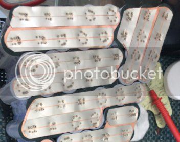
that looks pretty good, however i think there is no need to do the slit method between 2 nickel strips. the nickel should have enough resistance to weld the copper without doing the double strips. the copper will be taking all the series current so nickel wont be helping there i think, but it couldn't hurt either.
 
ridethelightning said:
i think there is no need to do the slit method between 2 nickel strips. the nickel should have enough resistance to weld the copper without doing the double strips.
Agreed.

And if you feel like you do need more resistance through the weld path, just use nickel plated steel. The side benefit is that it is cheap and plentiful, and you don't have to worry that you're not getting genuine nickel. Get the cheapest crap, and you'll consistently get nickel plated steel every time!
 
Ridethelightning:

I saw they are still selling the massive FET switch. I can't quite read the part number on the FETs, do you know what FETs they're using? I'm so tempted to just order one, but they're using TO220 FETs, and I couldn't find any with really high peak current rating. It depends on them turning on together, so they share. The array is pretty big, sounds iffy. And yet, it's working!

And that timer board drives the gates directly?

I do happen to have 20) A123 cells (26650 LiFePO4) with heavy tabs already welded on them. I could make a 4S5P pack out of them that would probably get the job done... I also have a 1.2F 80V cap bank left over from my first attempt at a cell welder a few years ago. I could put that in parallel with the A123s and probably have plenty of overkill.
 
67carguy said:
I saw they are still selling the massive FET switch. I can't quite read the part number on the FETs, do you know what FETs they're using? I'm so tempted to just order one, but they're using TO220 FETs, and I couldn't find any with really high peak current rating
indeed, but what you cant see is that the fets have a little ferrite ring on the gate legs, i think this its to turn them on evenly.
he also sells the fets:
https://www.yousun.org/product/hy4008p-to-220-80v200a-2-9m%cf%89-n-channel-mosfet
but the board is still a bargain! i think he is a rare vendor that isnt just economically motivated, more hobbyist that likes to tinker like us :lol:

67carguy said:
And that timer board drives the gates directly
yep, pretty much, there are some tiny surface mount resistors on the gate tracks, but like every 3 fets or something.

the a123 cells would probably do the trick. with nickel sandwich, its not so hard to weld copper but its nice to have more power than you need. a faster weld pulse period(and therefore the higher the power required for same energy) seems to make a better cooler weld with no marks of heating. so ultimate would be like 12v 20000A @0.5ms 8)

this is why i see people get by with mot welders but the welds are often discoloured from overheating cause they took too long, even on 0.2 nickel.
 
67carguy said:
BobBob:
To play devil's advocate:
With 112 of something, automating the process is difficult to justify.

True. BUT, in defense of my silliness on the automation front, this is, after all, a hobby (at least, for me it is). That means I really should enjoy it. I really enjoy building the car. I really enjoy designing the battery. My day job is technical and interesting, but I don't get to set the rules very often. Doing 112 x 40 x 2 x 2 = 17920 repetitive cell welds does not sound exciting, or interesting. I'm thinking I would likely stop enjoying this after perhaps 100 welds... I'll be honest, I had not considered some fixturing aids to manually weld them, but I don't think that would help enough. Now, rigging up an X-Y table to automate the process and allow me infinite flexibility, now THAT I think I will definitely enjoy.

Plus, there's the whole issue of quality and repeatability. I really want to make sure I don't blow a hole in a cell. Or slightly miss one. Automating it is a great way to get consistency. And, to be honest, I was shocked at how inexpensive a simple X-Y table is to build. So I'll have fun, I'll learn something new, I'll get a better battery, how can I go wrong???

Yeah, the automation is a more fun project, I'm being mr boring sensible. Do the XY table, post videos :)

And for quality and repeatability, jigs and fixtures would help more than automation, making sure the cells and strips are in the right place with respect to the probes matters more than getting the probes in a repeatable place in space.

It doesn't make it fun to weld though, so put a guide to make sure the probes go to the right place on the cell (if it fails to steer the probes to the right place it hits plastic so doesn't blow a hole in your cell

For info the FETs in my welder are IPT004N03L and do 1200A for short bursts or 300A each DC in a PG-HSOF-8 surface mount package.
It has 6 driven by a single MCP1406/07 and they have parallel 30 ohm resistors into the gate so they turn on together.
Gate Rising time around 1 micro Second to saturation
Should do 3600A for 10 mS or 7200A for 1 mS and the power PCB is easily stackable though needs bus bars if you want 20,000A lol and a freewheeling diode and safety specs. Can't beat the Yousun price and array of MOSFETS though for sheer capacity

Rectifying and sticking the MOT into the caps might resolve the intermittent power/double pulse problem.
Also, work out how fast you need to charge the caps - you may need the MOT and rectifier to keep up with the automated weld
 
BobBob said:
For info the FETs in my welder are IPT004N03L and do 1200A for short bursts or 300A each DC in a PG-HSOF-8 surface mount package.
It has 6 driven by a single MCP1406/07 and they have parallel 30 ohm resistors into the gate so they turn on together.
Gate Rising time around 1 micro Second to saturation

Interesting. I'm ashamed that I did not think about running slower gate drive. 1uS is considered crazy slow in the world of switching power supplies, but I guess it insures that as the FET's start conducting, and the first few FETs start to conduct, they should operate as current sources for a fraction of a microsecond and therfore not be blown by too much peak current. High speed operation might be 1 per second, so it's essentially a single pulse. The ferrite beads on the gates will prevent VHF oscillations while they're paralleled in the linear mode. Looks like that 72 FET board may be well designed!

You mentioned your welder uses the IPT004N03L on a small power board that might be stackable. Is the board available online? Either the bare board or loaded would be great. Those are very nice FETs but they really need to be soldered to a PCB.
 
I was also surprised at the 1 microsecond (uS) rising / switch on/ saturation time as the datasheet for the driver chip only goes up to 60 nS but the capacitance of one of these FETs is above the driver's rated specification and there's six of them in parallel.

I can see why you'd want to keep gate voltages similar to balance the power, guess the resistors help this, charging up the capacitance of the FET gate at the same rate? I haven't dont (m)any calculations or modelled it.
I stuck a cheapo DSO on the probes, accross the FETs and accross the supply and everything looked good after reducing internal resistance from 11 to 3.7 micro Ohms which I was happy with as a mild mod

Had assumed the single 6A driver was just due to cost rather than intentional for a slow switch on. They advertise the expensive imported driver chip in the Ebay ad so it was clearly a problem (as you'd expect).

There are no ferites on the gates - that was ridethelightning's 72 FET monster board.

Regarding stacking - the welder comprises two PCBs connected by standard 0.1 (inch / 2.54mm) headers and brass pillars at the corners with a cover plate top and bottom. The pillars are already the right size for the capacitor so minimum modification

I was thinkging that by getting another power PCB, all you'd need to do was extend the headers. At £20 for 6 built I'd have trouble getting the FETs at that price so was thinking of just buying 2 welders if I couldnt convince the seller to sell me a second power board.

Would add copper bus bars to the PCBs - maybe both sides for heat and resistance

The driver chip is on the control board and you may want one per bank of 6 FETs so I was vaguely considering piggybacking a second on the first (yeah, horrible but it's for me not a customer)

There's a cap accross the supply for smoothing which seems the right place for a TVS diode and it'd be easy to put a freewheelign diode between the probe connection
There are some diodes going from the -ve to the gate which I wasn't sure about function.

The controller allows timing from 1 to 99 mS and display.
No automatic duration compensation for varying resistance but it's 20% of the price
There is an auto trigger function that detects voltage acrosss the probes and welds after a bleep or a manual switched trigger

I've had it running at 1600A but need another battery for 0.3 pure nickel (bit silly as most of the power goes straight through the nickel rather than the cell)

A bit more info here
https://endless-sphere.com/forums/viewtopic.php?f=14&t=108047&p=1581204#p1581204
Ebay in uk is here
https://www.ebay.co.uk/itm/Portable-18650-Battery-DIY-Mini-Spot-Welder-Machine-Various-Welding-Power-Supply/313190994895
 
Hi,

I'm looking for some feedback on some tests welds. This was 0.1mm copper with no slit with a small square of 0.15mm nickel plated steel strip on top. I used an empty test cell so I could cut it open see the welds from the other side. The welder is an arduino spot welder powered from a 12v 930CCA lead acid battery. I found that with 30ms weld time there was good adhesion but insufficient to tear the copper over each weld when separated. With 35ms all six welds tore both copper and steel strip when ripped off with pliers (couldn't remove by hand).

The welds look really good to me and are extremely strong, could do with some experienced feedback though particularly on the shot from the inside of the cell before I tackle the 130 samsung 40T I have on the bench.

IMG_20201217_172828 (Large).jpg
IMG_20201217_170607 (Large).jpg
IMG_20201217_170614 (Large).jpg
IMG_20201217_171006 (Large).jpg
 
spinningmagnets said:
That's a great result, and thanks for posting the pics here. Can I use these pics as an example? (of course, I would credit you)

Yes of course.

But how do the welds look (I haven't got anything to compare it to) are they too hot or OK? Also what pulse duration do people usually use on the arduino welder? I've now reduced it to 32ms which still gives an excellent weld.
 
This is why these pics are important, few have posted the inside of the can.

Use the lowest setting that forms a solid connection, and then...whatever the inside looks like is the standard to measure by.

Also, if the setting you are getting good results with makes the welder very hot, you might get the same result with a lower setting by adding a one-inch split to the nickel/steel, and an "infinite" split to the copper (use two thin strips, instead of one wider strip).

Was there a plastic washer between the bottom of the can and the battery roll of active material?
 
Looks like too much current/heat from the pic of the cell’s inside. Basing that view on what “good enough” welds look like on the outside after ripping the strip off.
 
spinningmagnets said:
This is why these pics are important, few have posted the inside of the can.

Use the lowest setting that forms a solid connection, and then...whatever the inside looks like is the standard to measure by.

Also, if the setting you are getting good results with makes the welder very hot, you might get the same result with a lower setting by adding a one-inch split to the nickel/steel, and an "infinite" split to the copper (use two thin strips, instead of one wider strip).

Was there a plastic washer between the bottom of the can and the battery roll of active material?

They were empty cells, literally just the shells, using them to get the welding settings correct. Do you know of any pictures anyone has taken of the inside of any cells after welding that I can compare to?

I will do some more tests this time with just steel-copper-steel strip sandwich and see what the weld base looks like.
 
Some more tests still using the empty cells.
1. 0.15mm pure nickel 10ms - ok weld but not enough to tear the strip on all spots
2. 0.15mm pure nickel 17ms - excellent weld
3. 0.15mm steel -> 0.1mm copper 35ms - excellent weld

Test 1 is not really any good as the weld wasn't strong enough, however tests 2-3 show similar 'damage' to the rear of the cell so assuming (massive assumption) the nickel weld is ok for cell health then presumably so is the copper weld. The only difference visually between the two is you can see copper penetration on the rear of the cell if you look closely at the weld centres.

These dummy cells are empty meaning there is air behind the negative terminal, this makes a huge difference to the amount of power required to weld the cell. I did some more tests with bits of cell wall from the cut up cells onto an srbp plate, this is quite good as you can see the damage caused to whatever is behind the negative terminal, it can be quite significant.

I then took an old real cell, a 30Q and put a steel-copper sandwich on it with 26ms for a full tearing weld.A good weld can be achieved at 22ms. So the next step is to sacrifice a 40T to tune the final weld setup, I reckon it will be very similar to the 30Q.

Finally the cheap nickel plated steal works 100x better the pure nickel for the copper sandwich weld as others have already stated.

IMG_20201217_222353 (Large).jpg
IMG_20201217_222408 (Large).jpg
IMG_20201217_222414 (Large).jpg
 
I have now done some experiments with 0.2mm copper and the arduino welder in an sandwich. I can get a reliable connection through the first layer of 0.15mm nickel into the copper however not from the copper down to the cell. If I take a strip of nickel and bend it so it wraps around the copper then spot weld from above I get an excellent weld from the top nickel into the copper and an OK weld through to the bottom layer of nickel. With this in mind I have come up with a plan and would like your thoughts.

1. Make series connections between pairs of cells using 0.15mmx10mm nickel, make the strips longer than they need to be, weld these down to the cells as normal.
2. Place a 0.2mm copper plate over the series strips covering over the cell ends.
3. Bend the first layer of nickel series connections back over the top of the copper.
4. Turn the spot welder up to 70ms and weld down through the sandwich. This generates a lot of heat in the copper but not much at all in the cells.

I need 22.5A 30s bursts per cell, this method would give me 0.15x10x2 = 3mm^2 nickel plus 16x0.2 = 3.2mm^2 of copper (copper plate is 50mm wide covering 3 cells to 16mm per cell).

IMG_20201223_174802 (Large).jpg

Does this sound reasonable?
 
Its possible that most of the current is passing through the copper from one probe to the other, with almost none going through the cell-tip. Perhaps try slicing the bus down the center, so the left and tight half of the bus is not touching each other. Here is one example...some have called this an "infinite slot"

file.php
 
Thats what the builder said. Adding a cap of nickel or steel works so well, you can get acceptable results with a much lower energy setting on the welder. Personally, I would use the infinite split and also a steel cap to the "sandwich". Steel has more resistance (heat) than nickel, along with being cheaper than nickel.

https://endless-sphere.com/forums/viewtopic.php?f=14&t=108006

file.php
 
But in a salt spray environment, steel corrodes too fast.

Nickel plated steel better than pure nickel?

But just plain copper would be great if there is a HowTo formula for the reasonably-priced spot welders
 
Splits don't seem to help much with 0.2mm copper with my arduino spot welder the problem is the overall thickness of the layered buildup and the massive heat sinking of the thicker copper. As I said above you can get excellent welds onto the cell with 0.1mm copper and plated steel patches. 0.1mm copper is not quite enough for my usecase and multiple layers of copper doesn't work very well.

I'm going to go with the pure nickel series strip onto the cell, then 0.2mm copper with the series strip bent over the top as I drew above. This gets the best of both worlds, excellent adhesion of the nickel to the cell, excellent adhesion of the nickel to the copper and ok adhesion of the copper to the nickel over the cell tip and very little heat into the cell.
 
I thought the cell casing was nickel or perhaps nickel-coated? If this is so, what purpose does the first/bottom piece of nickel serve? Except perhaps ensuring a good weld to the cells before hiding it with the copper.
 
The north American retailer for kWeld has nickle-plated copper for series strips that are corrosion-resistant.

It's funny that over the years, people ordered pure nickel ribbon from China, and half the time it arrives as nickel-plated steel, making the builders angry. And now I find myself wanting a reliable source for nickel-plated steel for the welding-caps.

There are several welders available, and if your battery packs work fine with 0.15mm nickel ribbon it seems like just about any one of them works fine. Personally, I have a kWeld because I think it's fun to experiment with new things.

I'm pretty swamped right now, but if anyone has nickel-plated steel ribbon (rusts in saltwater, strong attraction to a magnet), I'd like to buy some off of you and I'll post pics of the results.
 
Back
Top