Spot Welding Copper Strips to 18650 Battery Cells

serious_sam said:
devmonkey said:
0.1mm copper is not quite enough for my usecase
What current (continuous and peak) do you plan per cell ?

22A per cell for 30s bursts, about 10-15A continuous (2 min bursts) although the whole system will be off for most of the flight. These are 40T cells.

The purpose of placing pure nickel down first is to get an excellent weld to the cell. Then placing copper over the cell tips and bending the previously welded nickel over the top of the copper is because the weld from the nickel into the copper is 100x better than the weld from the copper into the layer of nickel below it, this is also true with the 0.1mm copper and is obvious when you look at the path the weld has to take through the layup.

Basically from the hundreds of test welds I've now done I would not trust the welding in one shot from nickel through 0.2mm copper to the cell not to fall off eventually. I would probably trust it with 0.1mm copper but only just and then you are limited to 0.1mm copper as you cannot get another layer to reliably stick.

The method i'm proposing is a compromise but is reliable with the tests i've run and the resultant layup is extremely strongly adhered together.

The alternative for this pack would be 4 layers of nickel but I don't believe the upper layers are particularly effective current carriers.
 
I have no experience with this scenario but I like your plan. It's simpler than punching holes in the copper then welding or soldering nickel strips over the holes (which would then be welded to the cells). I'm building a 20S5P pack this winter for a friend's scooter and was going to experiment with the punched hole/soldered nickel but I like your idea.

I'm also planning a higher output pack with 450A bursts so thicker copper is definitely required. Please keep posting your results!
 
devmonkey said:
22A per cell for 30s bursts, about 10-15A continuous (2 min bursts)
IMO you're going overkill with the 0.2mm copper.

I run 30A peak and around 15A continuous with 0.2mm nickel plated steel over 0.1 mm copper. I stuck a thermistor on one of the connections when I built the pack just as a precaution (it's wired into my BMS), but I haven't had a problem. Cool running.
 
serious_sam said:
devmonkey said:
22A per cell for 30s bursts, about 10-15A continuous (2 min bursts)
IMO you're going overkill with the 0.2mm copper.

I run 30A peak and around 15A continuous with 0.2mm nickel plated steel over 0.1 mm copper. I stuck a thermistor on one of the connections when I built the pack just as a precaution (it's wired into my BMS), but I haven't had a problem. Cool running.

Is that 30A per cell? 30A thru say 22x0.1 = 2.2mm^2 copper is quite a lot is it not? Do you have a picture of your pack? I'm extremely constrained with the layout so I can only get 50mm of plate in there to carry the series current of three cells. 50mm of 0.1 is 5mm^2, at 75A for three cells that is 16A/mm^2, I think that is a bit high.
 
devmonkey said:
Is that 30A per cell?
30A per cell. 150A for 5P.
devmonkey said:
Do you have a picture of your pack?
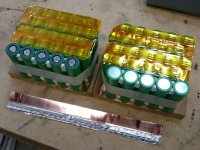
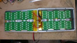
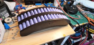
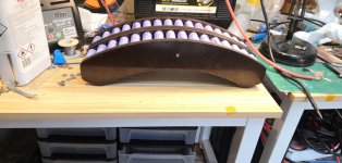
I have 4 groups of 5S5P (for a total of 20S5P). For connecting each group together in series I soldered some copper wire (approx 8AWG) along the end copper strips before spot welding.
1.jpg
2.jpg
3.jpg
 
Frank said:
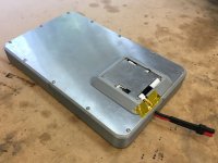
Nice enclosure! And even with restricted airflow you're not seeing high temps?
The cells get pretty hot, but it's not due to the interconnects. Pulling that much current from 18650s is pretty harsh on them.

The cells are bonded to each aluminium side panel, so they emit heat pretty well. After I finish a ride and take it out of the pack, it's not too hot to touch, and they cool down pretty quickly. Max temp is ~45°C (I've seen ~50°C on a really hard ride once).
 
I think you might be right that 0.1mm would work for me. I just used a couple of online pcb trace calculators, taking a strip of 0.1mm copper, 16mm wide between two cells with a temperature rise of 5 degrees C it can carry 28A, 10 degrees 38A, I2R losses at 25A would be 67mW, voltage drop 3mV.

I was thinking about the capacity of copper wire however plate has massive surface area to radiate the heat.

Merry xmas!
 
Polyurethane adhesive - thanks for the tip.

Conduction area: I've also been thinking in terms of equivalent wire size but with good heat shedding it's entirely possible that thinner sheet might work in a higher power scenario.
 
devmonkey said:
I think you might be right that 0.1mm would work for me. I just used a couple of online pcb trace calculators, taking a strip of 0.1mm copper, 16mm wide between two cells with a temperature rise of 5 degrees C it can carry 28A, 10 degrees 38A, I2R losses at 25A would be 67mW, voltage drop 3mV.
IMO the limiting factor will be heat in the 40T cells, not the interconnects.

Maybe if you were using VTC5A (30A continuous) you could push the limits of 0.1mm copper, but not with 40T.

You could ask Ridethelightning about large currents and copper thickness. He uses VTC5A and copper sheets. I can't remember what thickness though.
 
serious_sam said:
Frank said:
Can I ask how you bonded the cells to the aluminum side panels?
Polyurethane adhesive

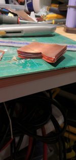
Just to pursue the details a bit more: am I correct in assuming the cells are glued to top or bottom of the enclosure and that is where they're bonded to the aluminum? Also, it appears you folded the copper after welding to fit all the cells into the enclosure. Is there any meaningful compression "end to end" i.e. so each parallel group has better contact in series with the group next to it? I know of at least one large pack built that used this technique to enhance series conductivity but those cells were stacked vertically.
 
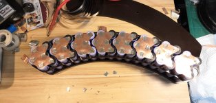
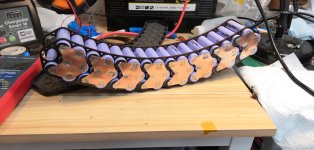
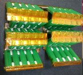
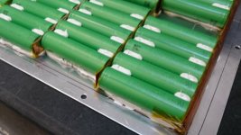
I've welded my packs up, 2x16s3p 40T. I used 0.1mm copper and plated steel patches, arduino welder , 800cca and 25ms. Went very well although electrodes get hot so a few pauses, took about 2 hours.
IMG_20201225_212724 (Large).jpg
IMG_20201226_104949 (Large).jpg
IMG_20201226_105520 (Large).jpg
IMG_20201226_115253 (Large).jpg
IMG_20201226_115308 (Large).jpg
IMG_20201226_134926 (Large).jpg
IMG_20201226_134939 (Large).jpg
 
serious_sam

whats the brand of polyurethane adhesive? I have heard that "Liquid Nails" construction adhesive has specific properties that work well for certain applications. It "fills" gaps to a certain extent (unlike Cyano-Acrylate "CA" glue), and after curing, it has a rubbery consistency, rather than being brittle.

devmonkey

Thanks for posting these pics here. Also, the type of welder and the setting is very useful. What was the power supply, was it a car battery? If yes which make and model?
 
Frank said:
Just to pursue the details a bit more: am I correct in assuming the cells are glued to top or bottom of the enclosure and that is where they're bonded to the aluminum? Also, it appears you folded the copper after welding to fit all the cells into the enclosure. Is there any meaningful compression "end to end" i.e. so each parallel group has better contact in series with the group next to it? I know of at least one large pack built that used this technique to enhance series conductivity but those cells were stacked vertically.
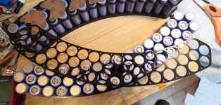
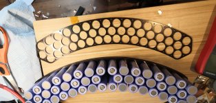
The cells were glued in groups of 5 first (using removable spacers to maintain about 0.5mm gap between while the adhesive set), then welded in 4 "bunches" of 5S5P, then welded into 2 bunches of 10S5P, then each bunch folded flat into "sheets", and glued to the 2 aluminium panels, again with about 0.5mm spacing for the adhesive to ensure nothing shorts out on the aluminium. So the 2x 10S5P sheets are each bonded to an exterior surface. When assembled there is about 2mm gap between the two sheets of cells, and I used some foam tape between them just to apply a small preload.

I insulated all the welds with mylar tape after each strip was welded on, so there is no contact when folded flat. There's no advantage to have them touching, and covering them up as I went ensured that I didn't accidentally short anything out during the weld process. The reason I say there's no advantage to having them touch, is because the surfaces are not perfectly flat so contact area would be poor, and its only the steel that would touch, so low conductivity, plus there's no preload to ensure consistency. Bonding the cells like I did makes a relatively rigid structure so the copper and welds shouldn't fatigue from vibration, but the adhesive is slightly rubbery (shore 40A), so there's some allowance for thermal expansion.

spinningmagnets said:
whats the brand of polyurethane adhesive? I have heard that "Liquid Nails" construction adhesive has specific properties that work well for certain applications. It "fills" gaps to a certain extent (unlike Cyano-Acrylate "CA" glue), and after curing, it has a rubbery consistency, rather than being brittle.
Sika 221 or 227. Both very effective. Kinda like silicone, but stronger and stiffer.
02.jpg
01.jpg
03.jpg
 
devmonkey said:
I've welded my packs up, 2x16s3p 40T. I used 0.1mm copper and plated steel patches, arduino welder , 800cca and 25ms. Went very well although electrodes get hot so a few pauses, took about 2 hours.
Neat assembly. What is it going in ?
 
serious_sam said:
devmonkey said:
I've welded my packs up, 2x16s3p 40T. I used 0.1mm copper and plated steel patches, arduino welder , 800cca and 25ms. Went very well although electrodes get hot so a few pauses, took about 2 hours.
Neat assembly. What is it going in ?

Its going on a hang glider.
 
spinningmagnets said:
devmonkey

Thanks for posting these pics here. Also, the type of welder and the setting is very useful. What was the power supply, was it a car battery? If yes which make and model?

Battery is a Numax XV31MF Heavy Duty Ultra Deep Cycle Leisure Marine Battery - 12V / 105Ah / 740EN / 925MCA.

Not mine I borrowed it from the guy i'm building the pack for, it is brand new. CCA is rated at 740A.

https://www.amazon.co.uk/Numax-XV31MF-Leisure-Marine-Battery/dp/B0761TW797/
 
Manufacturer ratings are often "fuzzy", but it is extremely valuable to list the type, because you found a combination that works. As you mentioned, this one is rated for 740 Cold Cranking Amps / CCA.

If it actually puts out only 700A, it is of no concern, because this model works for this job. In fact, it might even put out 800 CCA, which would be better than advertised. The key factor is that with this welder, at this setting, we can be certain to get a reliable result.
 
Back
Top