new eZip motor

Status
Not open for further replies.
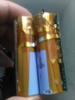
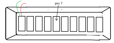
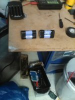
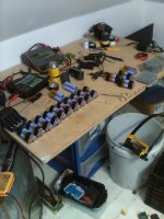
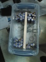
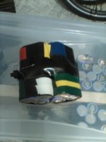
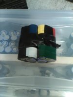
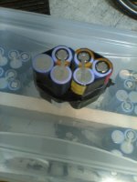
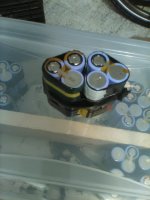
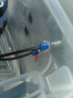
Trying to figure out how to take them apart without shorting them out ?

Since I never did anything like this before I could use a little advice so I do not damage cells.

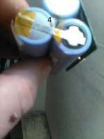
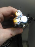
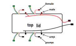
Since the main battery connections are numbered how would you cut those connections,

Example - 5 , 4 , 3 , 2 , 1

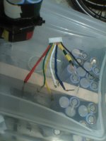
Just please tell me what order to snip those tabs as I want to hook up 6S balance wires and wire them together for 6S packs.

I do not think it is possible to hook balance wires to them the way they are or is there ?

It reminds me of movies where they diffuse a bomb. I just watched the news where that guy blew up the AT & T building in Nashville while playing downtown and warning people to run. :lol: :lol: :lol: :lol:


https://www.youtube.com/results?search_query=downtown+clark+petula

Absolutely hilarious.

I just can't figure why an AT & T building. ?????

I am very surprised people have not been blowing up hospitals. A lot of very high risk patients have been turned down for health care as they did not think they could be saved and needed room for patients that had a better chance. They were told to just go home and quarantine. :roll: It was on the news.

These are very desperate times. Imagine someone's wife or husband and how they would feel if their spouse was denied health care and died. I would not blame them a bit if they blew the building up. Especially when the hospital is full of younger folk at less risk for mortality and they were the selfish frocks out there with no mask on attending COVID parties to catch it or running around protesting and looting with no mask on.

That is why everybody is still sick. I have been wearing an electric mask and a face shield for over 8 months now and if everyone did the same there would be almost no cases today.

Please let me know about how to cut these packs open.

Thanks.

LC. out.
 

Attachments

  • IMG_0561.jpg
    IMG_0561.jpg
    148.8 KB · Views: 601
  • IMG_0562.jpg
    IMG_0562.jpg
    129.4 KB · Views: 601
  • IMG_0564.jpg
    IMG_0564.jpg
    123.5 KB · Views: 601
I may have missed the context of when you ordered these, but they are obviously for a specific application. See the photo of the numbers with the grille just above those? In between each gap is a metal contact. They make it that way so the contact can't short in a toolbox or something, and the grille has a specific spacing so you can't mismatch battery with tools.

You are going to have to essentially strip them down to nothing to use them.
 
The hacksaw worked.

I do see a spot on the cell that got damaged. Not sure if it was me. The arrow on the bottom points to it.

IMG_0561.jpg

Yea. This is going to be a nightmare.

Thanks.

LC. out.
 
latecurtis said:
I do see a spot on the cell that got damaged. Not sure if it was me. The arrow on the bottom points to it.

Tape over it. The metal case on some 18650s is negative. Might or might not be on this one, but you don't want to risk shorting it there.
 
You are going to have to essentially strip them down to nothing to use them.

Perhaps not.

https://www.youtube.com/watch?v=xeGKxYnv32A&feature=youtu.be

The method to my madness was to hook up a 6S balance plug to 6 cells in series so that I can monitor every single cell voltage.

I see a 3S pack with minimal stripping. A second in series is 6S and then just need to solder the balance wires where they need to go and tape the two 3S packs together.

The negative and positive wires will go to terminals.

The only other thing I will need to do is figure out how to keep them from sliding around. I could use hot glue but would be messy. Gorilla tape maybe but would like to be able to pull out unbalanced 6S - 1P and replace with balanced 6S - 1P packs. Maybe PVC or something they could slide into. Basically I was going to have a bunch balanced charged and use one LiPo charger to bulk charge and a second to balance charge.

I ordered a 100 male and female spade connecters and was going to hot glue the males into the sides of the container and the female spades to the wires. Also am using female bullets black and red and males coming from the controller black and red. reverse polarity is not as bad as a dead short but will remember to wire a 60 amp fuse in before the red bullet.

Ok. The second one came apart a lot quicker. same result. 3S intact but read 10.98V so will have to do this for each one and there is a lot of them to do. After that I will test voltages and combine the 3S packs that are closest to the same voltage for 6S packs.

Thanks.

LC. out.

Untitled.png
 

Attachments

  • download.png
    download.png
    21.5 KB · Views: 582
  • Untitledq.png
    Untitledq.png
    4 KB · Views: 578
  • IMG_0565.jpg
    IMG_0565.jpg
    228.9 KB · Views: 576
  • IMG_0566.jpg
    IMG_0566.jpg
    245.7 KB · Views: 575
Oftimes, I was able to crack open cases by getting cold in freezer then tapping at seam.
Small hammer, wrench or even screwdriver handle.
 
IMG_0567.jpg

I found the charger for my old beat up Cannon camera the other day. The screen is broke but still takes pics and shoots video. I will show how I take these apart.


Well I got 7 of them open and tested. 5 out of 7 are over 10V but two of them are not. I got one at 2,45V and 1 at .80V.

Not sure what to do with those.

Will they even charge ? I may have to separate them. Not sure.

I wanted to keep them all at 3S and then combine for 6S but with those two being that low I really don't know.

What should I do ?

Please let me know.

Thanks.

LC. out.

12/31/20

https://www.youtube.com/watch?v=3Eb_AikYXZE&feature=youtu.be

12 good , 4 bad so far.

Yea. the hacksaw bit me. I will live.

Not sure if I can bring the bad ones back. They are really low.

Please let me know.

Thanks.

LC. out.
 

Attachments

  • IMG_0571.jpg
    IMG_0571.jpg
    274 KB · Views: 565
As the Hub Motor Turns and the LiPo Fire Burns.

I have 20 - 6S balance plugs being shipped and just checked the time and do not like what I am seeing. Jan - 17 to Feb 9 I think it said.

I really want a functional 12S battery A.S.A.P.

It looks like I will need to explore a different option here. There is another seller where I can get the same cheaper and by Jan - 7.

I will probably do that but am thinking what I can do to charge and balance cells sooner. I would like a 1,000W - 48V pack in a few days. I will need connecters that can plug into a single 6S balance plug coming from the charger. That way I can start building and balancing 6S packs now instead of waiting around for two weeks or two months.

Thanks.

LC. out.
 
Your cases look flimsy, instead of using up precious time getting the screw driver out, then a flat head screw driver and this that and the other I just took an angle grinder to the Makita cases of 5S2P, took the bms off via drill and snips, took the 5s2P out via flat head screw driver. After the first and second one you know where to attack. In Makita case there was plenty of room to attack removal of case.
 
It sounds like a good idea however my grinder is a tool that is rather cumbersome and large for the job. However I do have a couple Dremel tools I will look at. With a small grind wheel it could do the trick without damage to the cells I think. I do not have much confidence in using that grinder to open these things up.

Yea. I see your point though,

My brain is telling me to just pick up the hacksaw and screw drivers again but my finger is talking to me and saying "HELL NO"

IMG_0574.jpgIMG_0572.jpg

I am kind of distraught as I have no way to balance charge these cells after I combine them for 6P and I really need to start balance charging as if I wait until the end of January or some time in February to start as the way it looks is it could take a month or so to balance charge all of these even if I do 5 or 6 - 6S - 1P - packs a day. I do not even know how many cells I am dealing with. 150 I thought. I never counted them.

IMG_0575.jpgIMG_0576.jpg

There is no way I am getting any balance plugs here any time soon and that sucks. My only option is to use 2 balance plugs to balance two dozen packs which means I will need to wire up some kind of female connecter to each pack where a balance wire would go so they do not short by touching each other and connect a male plug to each balance wire coming from the two balance plugs. I will need some paint or more colored tape as all connections have to be colored so I don't screw it up.

The only place I know to get any kind of connecters is Auto Zone. Most Radio Shacks are out of business and do not see many electronic stores open. To be honest I wish I never ordered these as I could have bought a 20 or 35 Ah - 48V pack already built. This will take a very long time to accomplish. I would have a more positive attitude if all the balance plugs were here and the 100 male and female spade connecters were also here now.

If I wait until the end of January or February to start charging and balancing then I wont have a decent running pack before spring. My only hope is to get both LiPo chargers charging packs A.S.A.P.

thanks.

LC. out.
 
You need to start thinking outside the box!

So I assume you have an RC charger, typical type. I remember those daze well, I would cut up some 3S balance leads to make one 2S and the other was 3S and carefully put them side by side on the rc balance connector for a 5S balance lead. But you dont have balance leads so you need to think outside the box even more, but cant come up with anything because those pins for balance connector ON rc charger are very close together. I guess it all comes down to buy more then you need, have spares. If you got the balls, open up the RC connector and see where on the pcb board those balance pins go. Then hopefully you have a thin tipped soldering iron, another hurdle you may have to jump, and steady hand, yes another hurdle your beer drinking hands need to jump over. Plan Z maybe hit up the ole bum shop aka thrift store for some cell phone chargers and read their ratings on the plug, fine print so maybe another hurdle your eyes need to jump over. Key point in that method of attack is not so much voltage cuz you can baby sit, but amps as you dont want to much amps right, voltage can be 5V but you need 4V so you baby sit the mofos with your dmm.
 
IMG_0577.jpgIMG_0578.jpgIMG_0579.jpg

Yea.

That is the cold hard facts in the top pics. It is all I got to work with to balance charge and build a 12S - 10P - pack

download (25).pngdownload26.png

The shit I need to make this work is somewhere being shipped. That wont help me now.

I will have to find what I need at Auto Zone and Wall-Mart to get anything accomplished. I have no choice.

12/31/20 - 6:03 PM.

Wall Mart stays open until 10 PM and Auto Zone 8 PM. I am charging my electric mask and sterilizing my plastic face shield and putting winter cloths on. I won't be taking the van as I need exercise desperately. I do not like being a fat person and is bad for my health.

I have figured out how to mount the packs for 6S - 10P however will need a second container for 12S which I can get at Wall-Mart. They come in a set of four I think. I need to take measurement's as have some wasted space in the center. The male spade connections will go above the cells and wont be able to do negative one side and positive on the other as both connecters have to go above each pack or things will get confusing.

IMG_0580.jpg

I am thinking a bunch of colored dots in the arts and craft section. I would like to put a dot on the cells also for soldering the balance wires and red and black dots under the male spade connecters over each pack. The simple part will be drilling small holes and zip tying each 6S pack to the sides. The series connection will go on the bottom and negative and positive will come off the top.

Well. I need to get my ass in gear to get anything done.

Thanks.

LC. out.
 
Your freezing and I have the AC on??? Only low 80s today, Gonna get cold soon, like 50s.
Has been almost freezing last week!

You don't wanna solder on the cells any more than really needed.
It looks like your gonna solder direct to the cell not tabs, They really don't like the heat, especially the negative/case side.

Hope you and all have a Happy 2021 New Year. Hope 2021 is better for all of us than this year has!

Dan
 
Waltons or Auto place aint going to have the shit you require mate.

You need an RC store, you'll only have one in your city if the city is big enough say 30k+ is my guess but you may luck out and have an RC store in the stix.

My solutions are valid, I've done the small plug in cell phone charger method many times to charge up my old Makita tool pack batteries when I fried my RC charger. Those Makitas come in 5S2P for tool packs with lots of tabs to solder onto, I'd just solder tabs between the two batteries and not right on top. Thats the only way you can do it for now. The only other way is to open up the RC charger and find out where the balance lead pins go to on the pcb board inside the RC charger. If you are skilled enough with high skill level abilities you could solder wire directly onto the balance pins on the RC charger, then use solder wick to take excess solder off when your done, to much skill level for 99.9% thats like assembly line smt tech/repair shit happening. I will slap out some pics for you in case we are on different pages.

Heck I bet even the USB charger would work, but I wouldnt risk from the computer/laptop but those small bricks with one usb slot, I'd bet that would work because I've seen 1S chargers from hobbyking taken apart and they were pathetic for safety but would work.

This link seems familiar from I saw years ago but it isnt because he shorted it, the one I saw was a pathetic drop down resistor.
https://www.youtube.com/watch?v=TqwX23sXQzc

Heres a teardown to see what the pcb looks like for balance leads pin pads ON PCB
https://www.youtube.com/watch?v=3LfU4mjgpyM

Ah yes this is the one I'm looking for
https://www.youtube.com/watch?v=ejU_97skXCg


22222222.jpg


2222222222222222223333.jpg
 
IMG_0581.jpg

Well It is a start. Yea I know the cells do not like heat but hopefully with my new solder iron I can do it quick.

I plan on ordering other balance plugs from a different vender. I won't cancel the ones I ordered as I plan on ordering more cells.

https://www.ebay.com/itm/US-SHIP-10-PCS-6S1P-Balance-Charger-Cable-22-AWG-Silicon-Wire-JST-XH-Plug/162529280314?_trkparms=ispr%3D1&hash=item25d780013a:g:In4AAOSwYvFZJ4cT&amdata=enc%3AAQAFAAACcBaobrjLl8XobRIiIML1V4Imu%252Fn%252BzU5L90Z278x5ickkfOCvCjTOBWK8pwriaolq5jIlgz5nTiVxCcFxzoivJW4GQ7jqosEvWXsvJzM2y%252BYNRmGiCVxcC5eFSu%252BBBzmxIROKiBKzDHLstQq%252BYQnSLJ4oLmcHmq%252FTATiDtgiRshyT0Seo1bmtA%252BV2Ma9YAjpXaXFK3T3p1u74fxxPfvTNRS0Yz4%252BCy8kLyjRHumeZ%252F8IIi6sgXhQNs85%252BgHUO2l1cTo0aqKvxKey%252FOcyPUMGVd1ZZbV5naeoIDRJ%252Bh80iwUkHVP%252F0lw23DJfxvn%252BahAqx1OKGRK6HrCS%252BVWZELpDjqpfG0C0pEaPBw%252F5dHwCfp8g8XPDKZaerHmCVn4gSZG7so%252BQprAuRXt4xxmfos1500ZCeRQ7DZI1YbBmbAMYbzEZGnQIjmHYJqzKWj%252F6EyypmBMxUCXQkB0Kp7Bb9Pk43JfHaIY4B9CaEFLSZMckUsZFNyq%252BsHc2fZXqihvsuvrqoGKgIpuncDtxGozkWmVaTj%252FDJxRLI39t4l6e2Dm86Y%252FIcIrj8LfEHcEihVWoOcxSbLPuHHI4c1kHMfK04w2yKXqi6MTkU1QeOzMvhZ9NZtvepjyiB1KowH4YLtNdo8B5hu2rqkfmtrhETufiZL1uSKrIFQJVAikLZP%252Fl6at59B7wN5efE5VFm5UDyGtkFKZcphby4e9%252BVp0djc%252B%252FrcYP%252FrClPb54dh3YB9uCVMxvnTLsqjCg82hTAwYY9VRyWh5jZrh0IWFPsLHlGszOGUtUvTOglxQdJclwyRR3ja9wf9Lz6hICErvmjIdscmPXdeJvCAg%253D%253D%7Ccksum%3A1625292803148fccabd599c7431ea297404c1da1bf1f%7Campid%3APL_CLK%7Cclp%3A2334524

download (25).png

I can use these small connecters to start though so I can start charging.

I think a lot when walking so thought about what to do with the space in the middle and came up with a great idea thanks to DA.
I remember a few pages back he mentioned running 14S to get the best performance from a 48V controller.

Since I can fit 6S - 10P on the sides then I can gorilla tape 10 cells in parallel in the center and charge it separate from the 6S packs. Then depending on the limitations of the motor I can hook up for 7S and hook in series to a second 7S set up and run 14S - 10P for 56V.

I do not call 10S - 36V because at full charge even with older cells it should be 40V. Also 4V per cell is easy to calculate. It does not matter if some cells are 4.1V or 4.3V. I would not want to mix brand new cells though that are 4.5V or above.

So using my math a 10S pack = 40V , A 12S pack 48V and a 14S pack = 56V. I would not want to run any of the geared hub motors rated at 36V above 10S or 40V. I also would not want to run the 36V - 750W gear reduction motor or the 36V - 1,000W motor at 56V but 48V should be ok. That leaves the 48V - 1,000W hub motor and the 1,800W 48V brushless motor for 56V. Also 56V should do the trick if I order a 60V - 3,000W brushless motor for the Haro V3. But that wont happen until I am running 14S - 20P.

Doing the math I am better off running the 48V - 1,000W hub motor at 12S or 48V as the 36V - 1,000W motor on the front is geared for 28 mph and the hub motor is also geared for 28 mph at 48V or 12S.

28 mph / 48V = 0.58 * 56 = 32.6 mph. - hub motor on rear.

download (27).png

Yea. Much better off going with 36V up front and 48V in the back.

Since the 1,800W brushless motor was rated at only 26 amps then 56V should do it justice and can get at least close to 1,500W out of it.

48 * 26 = 1.248W

56 * 26 = 1,456W

https://prnt.sc/wdyhb0

That is one thing I do not understand about DC motors and how they function. Is current a constant by design ? I know RPMs change according to voltage and watts also change by voltage but what about rated current and max. current. Obviously the 1,800W motor would need over 60V to achieve 1,800W but is rated at only 26 amps so did I get ripped off ? I paid about 140 bucks with shipping for a motor rated at 48V and 26 amps or basically a 1,200 watt motor. 48 * 26 = 1,248W. I only paid 62 or 64 bucks with shipping for the brush 36V - 1,000W motor which would put out over 1,300W @ 48V - 1000 / 36 = 27.7 * 48 = 1.333W.

Very confusing indeed. I do know however that brushless motors can be over volted more than brush motors so at 60V the 36V brush motor would over heat and self destruct but if 26 amps is the maximum then even at 66V I could not reach 40 mph as 66V * 26W = 1,716W. So basically I bought a 140 dollar piece of junk as at 1,333W and 48V I could hit around 33 mph and the brushless motor at more than double the price will only go about 3 mph more at 66V. that is terrible. :roll:

Please let me know. Thanks.

LC. out.

12/31/20 - 11:09 PM.

IMG_0584.jpgIMG_0583.jpg

Yea. 14S - 20P sounds great for the 1,800W brushless motor but for the 1,000W - 26" hub motor I am going with 12S - 8P.

I see four rows of 4 - 6S - 1p fitting perfect in that space. Two containers that size is ridiculous. I can find a water proof zip up bag to cover that and still have room up front for my 10S - 8P pack for the front motor. It will be 2 kilowatts total with both motors and both motors will have almost exact gearing at 28 mph.

Also once I get all the balance connecters hooked up I can use my Y balance cables to balance two - 6S packs with each charger so charging all 16 - 6S packs would be much faster than dealing with 20 - 6S packs for 12S - 10P. As long as I can squeeze 1,000W out of 12S - 8P It should work .

Please let me know.

thanks.

LC. out.
 

Attachments

  • download (28).png
    download (28).png
    2.8 KB · Views: 495
ou need an RC store, you'll only have one in your city if the city is big enough say 30k+ is my guess but you may luck out and have an RC store in the stix.

I called one yesterday afternoon before reading that looking for 6S balance plugs. They did not. RC shops are unreliable.

I need to order those balance plugs A.S.A.P.

I have a lot of work to do anyway before they come in. I have not even used my new iron. I need to be able to do quick connections.
I need practice. I may as well order a second iron with same amount of tips as I have a lot of wires to solder.

16 - 6S - 1P - packs. * 9 = 112 solder joints. 7 for balance and two for power each 1P - pack.
 

Attachments

  • IMG_0602.jpg
    IMG_0602.jpg
    215.7 KB · Views: 475
  • IMG_0603.jpg
    IMG_0603.jpg
    194.4 KB · Views: 475
  • IMG_0604.jpg
    IMG_0604.jpg
    186.7 KB · Views: 475
  • IMG_0605.jpg
    IMG_0605.jpg
    214.2 KB · Views: 475
  • IMG_0606.jpg
    IMG_0606.jpg
    215.2 KB · Views: 475
  • IMG_0607.jpg
    IMG_0607.jpg
    187 KB · Views: 475
  • IMG_0608.jpg
    IMG_0608.jpg
    165.5 KB · Views: 474
  • IMG_0609.jpg
    IMG_0609.jpg
    152 KB · Views: 474
As the Hub Motor Turns and the Hub Motor Turns. new eZip motor. / Currie upgrade.

NEWCONTROLLER.pngdownload (2).png

Well basically I paid about 25 bucks more but got a quality controller. I did not want to wait a month or two for slow economy shipping from China. I need to take this dual suspension down stairs and stick it in the van. Then bring the Currie up for upgrades.

I am thinking about a scrub down and maybe some sanding and a new paint job. DA. would know if it is possible to get original replacement stickers. Then in about 4 days I will have my controller to test the Bafang motors. One of the two will go on the front of the Currie for the upgrade.

The 750W gear reduction motor will stay on and the old rusty motor and pedal chain will get oiled up or replaced. I might need a chain tensioner for the pedal. I might even put a derailleur on it for gears. Not sure. I am thinking about a rack also for the triangle but want to see my new stickers.

As far as the 26" dual suspension It is an unfinished project. The 36V - 1,000W motor is installed on the front and the 26" hub motor is getting a brand new rim and spokes also but will be a couple weeks at least before I get the #25 roller chain for the front motor and the 1,000W - 36V controller for that might not show up until February so am looking at the end of February or the first of March before that can get done.

I will probably order two more Bafang motors and have one laced in a 700c wheel and order the 500W rear geared hub motor off of e bay for Easy Street my 700c Hybrid and build that before I finish the 26" dual suspension. I want to run 12S - 8P on that anyway and the way things are going it could be summer time before I get the pack built.

I picked up a Dremel tool at Wall-Mart for cutting to finish retracting the 18650 cells from the plastic cases but is nowhere to be found. Looking for the reciept to see if it was put in the bag. It was my smallest item and is MIA. That sucks and is basically the straw that broke the camels back. I am sick of that build. (the 26" dual suspension). parts are taking too long and that 12S pack will take basically forever to accomplish.

I already have 36V - 10S packs and the gear reduction motor on the Currie is 36V as well as the Bafang motor that I am installing on the front. Also the motor on E bay for the rear of Easy Street is 36V and two more Bafang motors if we get the $600 stimilus money.

I posted pictures of the controller. Does anyone know what throttle is required for that controller ?????

Please let me know.


download (3).png

Never mind. I found it. Amazon might be more money but you get stuff a lot faster and has more stuff from US warehouses so you don't have to deal with that really SLLOOOOOOOOOOOOOOWW boat from China they call economy shipping. Sick of that shit.


Thanks.

LC. out.
 
latecurtis said:
That is one thing I do not understand about DC motors and how they function. Is current a constant by design ? I know RPMs change according to voltage and watts also change by voltage but what about rated current and max. current.

Current is not constant in a dc brushless motor. Conservation of energy must be obeyed. Therefore if there is no work to do, the energy cannot be consumed.

So when you have the wheel in the air, and the only work to do is overcome friction and air resistance, it might only draw 1 amp. When there is a 300 pound guy on top of the bike and he wants to go 30mph, then it might consume 20A.

Motors also don't truly have a max current. As long as there is work to do, and power to do it, it will try to draw more current. If it were allowed to do so, it would heat up and start melting stuff. The role of the controller is to stop that.

A rated maximum would be the engineer's recommendation on how much you can draw without damage. This is as much art as science, as they don't know everything about how the user is going to use it. Florida in Summer, or Buffalo in Winter? 120 pound rider on flat ground, or 300 pound guy on long hills? Square wave, or sine wave?

This is why in most cases, you can double or more the rating without damage. But if you are the 300 pound guy in Florida with a love for hills using a cheap Chinese square wave controller... good luck to you.
 
Motors also don't truly have a max current. As long as there is work to do, and power to do it, it will try to draw more current. If it were allowed to do so, it would heat up and start melting stuff. The role of the controller is to stop that.

This is why in most cases, you can double or more the rating without damage. But if you are the 300 pound guy in Florida with a love for hills using a cheap Chinese square wave controller... good luck to you.

OK so basically no specs are constant and all subject to change and basically it boils down to is heat. How many watts can the motor put out without overheating ???. makes sense I guess.

I think you may have got Florida confused with NY. Florida is mostly flat. I live in Ohio now and is a lot flatter than NY. I traveled to Florida 3 times and mostly flat.

I find it easier to run two motors to share the load as well as two controllers and two large capacity packs. My point is two motors geared about the same work with each other. One complements the other. It changes the overall dynamics.

DA. could show a graph. I cant. The currie rear 750W chain drive is geared for 18 mph I think and the geared Bafang might do about that so gearing is close enough that the bike will respond well. I would like to hook the power meter and use the new 10S 8P pack I bought last year for both motors.

750 + 500 = 1,250W. and gearing is < 20 mph.

A good cargo bike and may mount my bright 1,700 lumen front light.

When I do build the dual suspension total motor power both motors will be >2 kilowatts so will need to parallel the new 10S-8P to the old 10S-10P.

gearing for that will be 28 mph respectively.

Thanks.

LC. out.
 
Not that familiar with US geography, but I thought Florida was really hot all year round. Didn't know it was flat.

One of the few places in the US I have an interest in going is Boulder, Colorado. Years ago, I bought a book called "The cyclist's bucket list". Boulder was my number one in the book. Already knocked over the one in Australia. A couple in Europe I'd want to do too.
 
Fortunately, soldering to the tabs is super easy!
Oops, just looked back and saw you are ripping the end tabs off ... ?
 
Status
Not open for further replies.
Back
Top