famichiki said:
How's the torque compare to the TSDZ2, strong enough to get up steep inclines without overheating? And how do you find the torque sensing in comparison? Any delays or motor overrun issues?
Did you just use a standard bicycle chain for the drive chain? Any other problems now that you are not running a tensioner pulley, you mention the virtual freewheel helped.
Do you have any plans to print a cover for the motor or a chain guard?
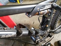
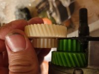
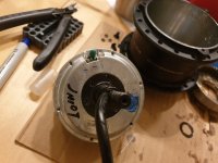
I was running the tsdz2 with max 550W, and I'm running this one with the same parameters. I would say its about the same torque. Difficult to compare. I was running the tsdz2 without temperature control, so I think I overheated it a few times. The case was too hot to hold my hand on. This one with the ATF oil I think is a little better, but I have temperature control now, so it ramps down before anythin bad happens. I usually put in about half the power from my legs, and I usually run it at very technical climbs, then down the same path. It doesnt overheat this way. On flat road it takes about 10 minutes with constant 550w before it ramps down. I think 400w constant would be fine.
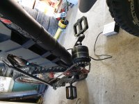
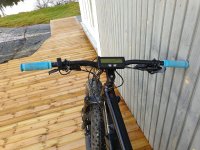
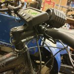
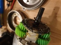
The delay on the tsdz2 is partly the reason I went this way. With the virtual freewheel keeping the drivetrain engaged, there is very little delay from coasting to full power compared to the tsdz2 which needs to spin up the motor and gears first. There is some slight overrun in certain cases that I am trying to tune out, but not bad at all. I want to tune it to be as responsive as possible, on the technical stuff, so that is the reason for the slight overruns. Still trying to find the perfect settings on the CA. Good thing is I can try out new settings when I am out on the trails, and dont need to wait to get back to a computer to flash new settings. Tuning it a bit softer for normal road/fireroad, etc is very easy.
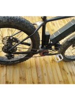
The motor chain is just a normal 10speed chain, so I only have ot carry one kind of spare links with me. Its doing fine so far.
Grantmac said:
Have you considered torque sensing via chain slack like the Lightest setup?
It would allow you to drop one chainring and the TS bottom bracket. Although if the chainline lined up correctly you could drop the second chainring immediately along with a significant amount of chain.
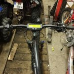
Any reason you didn't run the motor inside the triangle first either build?
Cheers,
Grant
Yes, I absolutely did consider the chain slack sensor. Rocky mountain bikes (I think) also has it this way. I could not find a sensor easily available, though, so I went this way. Did not do too much digging to be honest, when I found this BB torque sensor with freewheel I just bought it. Do you now here I could buy a sensor like that?
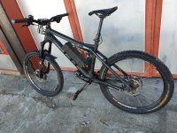
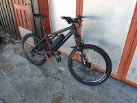
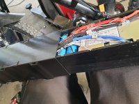
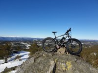
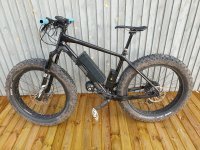
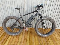
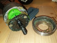
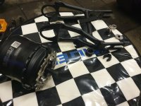
I wanted the battery inside the triangle, and the weight as low as possible, so that is why the motor ended up there. Its a quite safe position, even though it looks a bit exposed. The tsdz2 survived almost 1000km hanging below the BB, so I would be surprised if it gets damaged hanging the way it does now
")

.jpg")
.jpg")
.jpg")


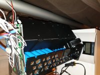
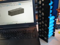
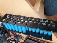
 Luckily it was enough space. The outer perimeters of the cell holders fit snug in the battery box, so there is no movement when mounted to the bike.