KT motor controllers -- Flexible OpenSource firmware for BMSBattery S/Kunteng KT motor controllers (0.25kW up to 5kW)

izy said:
stancecoke said:
izy said:
thanks is it possible to attach a current sensor or am i SoL

The footprint on the PCB looks like it could fit an ACS72981 .
You can check the dimension on your PCB. And you have to check, if there is a solder bridge somewhere that shortens the two sensing pads. This has to be removed of course.

regards
stancecoke

thanks finally does the current sensing and sensitivity matter much
theres multiple options
uTg7xJ4.png


also if you know any alternatives it would help due to extortionate seller prices

trying to find a site that sells it without charging an arm and leg for postage in UK seems to be a pain as digikey is only one i see with stock and they want £20 for it including postage the only toher site wants min order £20 before postage

seems lack of stock anywhere else

but if thats the case i may aswell just buy an actual controller https://www.aliexpress.com/item/4001093131407.html?spm=a2g0o.cart.0.0.77163c00rjTr1Y&mp=1

thanks again
izy

No it doesnt matter since we are only looking for the 0
crossing. The only thing that matters is that you get 2.5V Viout when you apply 5V on Vcc for 0A mesurement, otherwise you have to modify the code.

If it helps Ive ordered an ACS758 on Aliexpress (I have a 18fet version so it's a bigger sensor), 3euros and it came in 2weeks.
 
atkforever said:
No it doesnt matter since we are only looking for the 0
crossing. The only thing that matters is that you get 2.5V Viout when you apply 5V on Vcc for 0A mesurement, otherwise you have to modify the code.

If it helps Ive ordered an ACS758 on Aliexpress (I have a 18fet version so it's a bigger sensor), 3euros and it came in 2weeks.

Yeah i saw them when i initially was searching they came up that could work if its not too much wider (maybe trim it slightly?)

final question is did it work straight up attaching it or did you have to flash the firmware first?
 
Yes it is surely overkill for your board, check ACS711 or ACS712, you cand find them on amazon (mounted on a board, just unsolder it) or ebay, aliexpress...
RBVebabuBW3oLKTtjkTQqh5jpxT0fETuDuNk9ErYmXn-q7okNm-re6BvEfjUXHvEQ3vxz8i5yWXNWmR_z2rc_2BUtEJ2_lrvuFQ96nIJISzSyVRLQ59KCecjYRzlwRYXuWFJGa-3po-ZsH-RWez7

Since U have 2 pads you must bridge pins 1&2 and 3&4.

izy said:
final question is did it work straight up attaching it or did you have to flash the firmware first?

This has been already asked here, and no answer, please test for us :D
 
atkforever said:
Yes it is surely overkill for your board, check ACS711 or ACS712, you cand find them on amazon (mounted on a board, just unsolder it) or ebay, aliexpress...
RBVebabuBW3oLKTtjkTQqh5jpxT0fETuDuNk9ErYmXn-q7okNm-re6BvEfjUXHvEQ3vxz8i5yWXNWmR_z2rc_2BUtEJ2_lrvuFQ96nIJISzSyVRLQ59KCecjYRzlwRYXuWFJGa-3po-ZsH-RWez7

Since U have 2 pads you must bridge pins 1&2 and 3&4.

izy said:
final question is did it work straight up attaching it or did you have to flash the firmware first?

This has been already asked here, and no answer, please test for us :D
yeah abit overkill same with me getting 4110 mosfets instead of 3077
at least this controllers gonna be beefed up

so you mean the pins on the sensor yeah thats what threw me off getting them originally 2 pins 1 side

also that image doesnt load luckily im awake now so fond it easy enough I saw one guy in this thread who tested it and he was getting results similar to some sine controllers.

but yeah thanks again bought a pack of 5 for £5

at least now I have will have a spare beefed acs758 and 18 4110 fets left over when they arrive

im happy with my squarewave and 1500w direct drive but now i have the ebike bug gotta tinker
 
atkforever said:
Did you buy ACS758 ? i'm pretty sure they are too big for your board.
156463408_1342554006100553_5128328901037888677_n.jpg

I bought both alie already posted the 758 and both the smaller ones today should arrive Monday.

I will use it at some point lol
 
izy said:
final question is did it work straight up attaching it or did you have to flash the firmware first?

This has been already asked here, and no answer, please test for us :D

I am also in the process of upgrading a 18 fet square wave to ‘sine’ wave with custom firmware. I have just finished beefing up the traces with additional copper and lots of solder. And I have installed the 200 amp version of the acs sensor (in hindsight, I would have preferred a more sensitive lower amp one in combination with a beefy copper wire as bypass shunt).

Strange that the response after only adding the sensor has not been reported yet. I will test how the controller responds with the added current sensor before trying to switch to custom firmware, and report my findings here.

Ps: the beefing up is not finished yet; I will add some 8 awg power supply cables and a bunch of additional capacitors. Also move the resistor lm317 to the aluminium body for better cooling and peace of mind. This one will stay at 60v Max; I have also modded a more extreme version to buck converter + 100v mosfets + 100v caps + 400v snubblers + uprated cooling. That’s for another time.
 

Attachments

  • 6A758F27-AFF9-43C9-A0DD-B76423328092.jpeg
    6A758F27-AFF9-43C9-A0DD-B76423328092.jpeg
    379.4 KB · Views: 1,317
  • 85AE7B8B-CE36-4E94-9501-1CC62D1A9159.jpeg
    85AE7B8B-CE36-4E94-9501-1CC62D1A9159.jpeg
    569.3 KB · Views: 1,317
  • 1FA23096-4455-43C9-8177-85E0DC303900.jpeg
    1FA23096-4455-43C9-8177-85E0DC303900.jpeg
    531.4 KB · Views: 1,317
Iambuilderman said:
I am also in the process of upgrading a 18 fet square wave to ‘sine’ wave with custom firmware. I have just finished beefing up the traces with additional copper and lots of solder. And I have installed the 200 amp version of the acs sensor (in hindsight, I would have preferred a more sensitive lower amp one in combination with a beefy copper wire as bypass shunt).

Ps: the beefing up is not finished yet; I will add some 8 awg power supply cables and a bunch of additional capacitors. Also move the resistor lm317 to the aluminium body for better cooling and peace of mind. This one will stay at 60v Max; I have also modded a more extreme version to buck converter + 100v mosfets + 100v caps + 400v snubblers + uprated cooling. That’s for another time.
damn thats some beefy traces, mine came with metal on it already so i just beefed it up instead with solder.

im using a 12fet with a 48v/30a bms battery and i want to upgrade to a 52v/40a-50a bms battery so in hindsight my 100v fets are kinda overkill but i bought them more for the passive cooling bonus over the stock ones. will do my caps/snubs later the fets more important and sine. good idea about the lm317 i can use my spare wire/stlink wires (female to male) and extend it to the out the way.

my current controller is rated for 35A and 17 continuous for my 1500w kit but the sinewave controller for 1000W is rate 20A contin and 40A that and with my wiring the controller fits really nicely under my seat in the stock bag

my aim is to make it a sinewave and beef up slightly


what are you planning for uprated cooling?
 
atkforever said:
Yes it is surely overkill for your board, check ACS711 or ACS712, you cand find them on amazon (mounted on a board, just unsolder it) or ebay, aliexpress...
RBVebabuBW3oLKTtjkTQqh5jpxT0fETuDuNk9ErYmXn-q7okNm-re6BvEfjUXHvEQ3vxz8i5yWXNWmR_z2rc_2BUtEJ2_lrvuFQ96nIJISzSyVRLQ59KCecjYRzlwRYXuWFJGa-3po-ZsH-RWez7

Since U have 2 pads you must bridge pins 1&2 and 3&4.

izy said:
final question is did it work straight up attaching it or did you have to flash the firmware first?

This has been already asked here, and no answer, please test for us :D


small issue got the ac712 today

good size but

my solder points are 2 on left (yes can bridge legs)

3 solder points on right what do i do aboout this one

if i use the larger ones schematics this is how i should have it laid out

5vXu0ez.png


update i removed the bridge and i soldered it like above albeit messy with some small wires.


the controller still acts like a squarewave
lets see if firmware helps
 
right big update im in

flashed firmware I now have sinewave it definitely sounds like sinewave compared to old buzz


edit again so it turns out the sinewave model desoldered itself during the test i need a module that the right size but also fits and isnt costing an arm and leg

edit after reverting back to squarewave and flashing firmware i've noticed the sound is more noticeable now also my PAS really needs to calm down even at level 1 its really strong will try lowering it again

resoldered another sensor now and it desoldered itself
also whats with the torque and the really aggressive regen braking the regen braking so strong that it actually torques.

also my controller is showing me using 10-20w even when idle unless cycling


back on squarewave ordered a sinewave controller to save the hassle

the noise on the open firmware with interpolation off is worse than stock was which i would revert to if i knew a way too do it
at least new controller on way as a bonus i get a light wire

if anyone could helpe me configure the battery an phase current correctly it would be nice
48v 17.15ah battery with a 30A bms
1500w DD motor with 46 for P1 setting and this controller is rated for 17A continuous and 35A
oc1nDhu.png


Also 2 things extra I noticed the motor activates at 0 Assist
and when throttling with it linked to assist and you pedal while using throttle the motor actually slowed down
dunno if this acts when not linked
but kinda means I cant pedal while at max motor rpm to squeeze on some more speed
 
izy said:
desoldered itself during the test

you can solder a shunt or a power resistor, some mOhm, in parallel to the ACS sensor, as we need only the zero crossing not the absolute value from the sensor.

regards
stancecoke
 
well that was fun for whatever reason whatever settings i used without sinewave reported 800w peak usage

upped battery amp to 20amps ebcause 35A controlelr and 30a bms
my batteries bms actually blew mosfets
 
szkuba said:
stancecoke said:
I don't know, why the ERider T9 / T13 torquesensor always dies on a Kunteng controller. One guy in the german forum wasted three sensors this way. Now he uses a Lishui Controller and everything works well :shock:
Could it be due to different pull-up voltage on PAS pin? Measured voltage at free floating PAS input on Kuteng od 5,0V while at Lishui is 3,26V ?

Pretty interested in this as I think my sensor is slowly failing as well. Could this pull Up voltage be changed by a simple voltage divider?
 
Iambuilderman said:
izy said:
final question is did it work straight up attaching it or did you have to flash the firmware first?

This has been already asked here, and no answer, please test for us :D

I am also in the process of upgrading a 18 fet square wave to ‘sine’ wave with custom firmware. I have just finished beefing up the traces with additional copper and lots of solder. And I have installed the 200 amp version of the acs sensor (in hindsight, I would have preferred a more sensitive lower amp one in combination with a beefy copper wire as bypass shunt).

Strange that the response after only adding the sensor has not been reported yet. I will test how the controller responds with the added current sensor before trying to switch to custom firmware, and report my findings here.

Ps: the beefing up is not finished yet; I will add some 8 awg power supply cables and a bunch of additional capacitors. Also move the resistor lm317 to the aluminium body for better cooling and peace of mind. This one will stay at 60v Max; I have also modded a more extreme version to buck converter + 100v mosfets + 100v caps + 400v snubblers + uprated cooling. That’s for another time.

In reply to my own post: I have finished building and testing the controller (actually another 18 fet square wave after that) and I can confirm:

Adding an acs phase current sensor to the square wave version does NOT automatically render it a ‘sine’ wave version. BUT: it does provide the perfect basis for installing the beautiful custom firmware, see next post with my experiences as a newbie!
 
izy said:
Iambuilderman said:
I am also in the process of upgrading a 18 fet square wave to ‘sine’ wave with custom firmware. I have just finished beefing up the traces with additional copper and lots of solder.

[...]
damn thats some beefy traces, mine came with metal on it already so i just beefed it up instead with solder.

[...]

what are you planning for uprated cooling?

@izy
I use the blue 0.5mm thick heat transfer pads that you can find on AliExpress to improve the heat transfer from mosfets to the metal casing and still have electric insulation between mosfets and case. This stuff is quite flexible so it can be squished to a very thin layer if you tighten the nuts and use a wrench (?) to squish the top half of the mosfet backplate manually to the top of the case. If you have the controller in free air flow this keeps everything very well cooled.
 

Attachments

  • D6B24C62-C514-4F7B-B302-B025859AEC82.jpeg
    D6B24C62-C514-4F7B-B302-B025859AEC82.jpeg
    480.5 KB · Views: 1,071
@casainho , @stancecoke & all other contributors to this custom firmware:

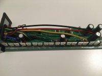
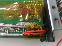
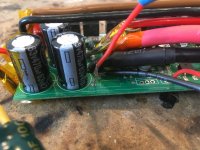
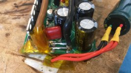
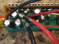
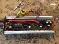
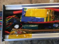
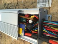
As I wrote in my previous posts, I just finished beefing up some square wave 18 fet kt controllers. As adding a current sensor did not magically turn them into sine wave controllers, I decided to take a leap of faith and installed your firmware.

And WOW!!! I am highly impressed, you have made a true piece of art! As a newbie, it was very user friendly to install. And more importantly: it works like a charm and looks very professional! Thank you very much, it really is the pie on the hardware optimizations that you can do to these controllers. It is very admirable that you are still taking the time to answer questions of other enthousiasts on this forum. It is really appreciated!!

As a newbie, of course I had to solve quite a few challenges. And I have some suggestions and questions about the Java tool and app, if those are still under active development. I feel I could help other users with the knowledge that I gained, maybe I should write some tutorials myself. Anyway, I will list the topics so anyone could ask me if they are interested.

My experiences with the Java tool:
1. very user friendly. You don’t need any programming skills to use the tools. Eclipse is not needed for a newbie; just the Java tool and the software tools that you need to install.

My experiences with the blueosec app:
1. It looks amazing and was clearly built by ebike enthousiasts!
2. You can use the graph of the correction value to determine the optimal motor specific angle (I think ;) ): run the motor at a constant speed, and change the specific angle until no correction is needed anymore. 238 is perfect
for my direct drive motor.
3. The wave table selection option is one of the greatest additions: the pure sine wave option is amazing: pure silence with ridiculous amounts of torque (once you set the phase amps you want). Pure sine wave is much more silent than the other wave forms!
4. The morse code to unleash the ‘Berserk mode’ a.k.a. Off-road mode is enough of a reason to install the custom firmware for any high powered bike user. The yellow font provides perfect feedback for having entered the correct code. If you switch off the ignition, you are immediately back to road legal. Very useful.

Suggestions for potential improvement of the bluosec app (these probably have been suggested by others before?):
1. Automatically apply the entered scaling factors for amps and volts so you can dial in the wanted limits in amps and volts directly without manual conversion into 0-255 values.
2. After applying suggestion 1: Display units in titles and descriptions
3. Automatic scaling of the graphs based on the entered limits (currently, my graphs are mostly out of sight due to high values). Alternatively, manually being able to set the maximum values for the axes would also help.
4. Show watts (or is it already there?). This is very useful variable for manual calibration of the cal a factor. For example, driving 50 km/h should take some 1000 watt without excessive wind speeds. And for comparison with other controllers or other power references as well.

Suggestions for improving the Java tool:
1. Add the WAve table option in The Java configurator as well, so that you can choose the pure sine wave for use with a display instead of the app (how can I change the code to do this manually?).

I think it is very important to mention that new users should take the time to calibrate the cal a and voltage calibration factors before accelerating their bike. The preset calibration value for voltage (67) was fine for me (selected the 48v dd preset), but the value for cal a was way off. It needed to be 21 instead of the preset 50 value. This could easily lead to blown mosfets because of way to high amps. I would advise to use an amp meter to calibrate this factor, by pressing the rear brakes while powering the motor (brake cable temporarily disconnected) and comparing the measured battery amps to the amps that the app reports. Alternatively, you can first check the voltage calibration in steady state with a multi meter, then drive 50 km/h and change cal a until amps*voltage=1000 watt (crude estimation).

I now drive my bike at a still moderate 80+ True battery amps in pure sine wave mode at a Kp value of 0.7 (set values: 95 battery amps and 310 phase amps). My 24 fet sabvoton controller does 150 battery amps and 450 phase amps out of the box with amp-wise similarly rated fets (actually higher rds), so I figure an 18 fet with great traces should be able to do 18/24*150=112,5 battery amps and 337,5 phase amps.

The only quirk that I found with the custom firmware is that if you brake quickly, the controller keeps powering the bike when you try to come to a standstill. It does not do this when you brake slowly or just let the bike roll to a stop. It seems to be connected to the pi-control? It “remembers” its previous power level and tries to stick to that.

I found that the solution is to enable a little bit of regen and to set the Max voltage high enough to enable this regen. With regen active, you can brake immediately and the scary auto-throttle does not occur anymore. So problem solved.

List of experiences I could tell about (all 18 fet controllers):

1. How to convert a 48v into 72v version
2. How to connect a buck converter to replace the lm317 + resistor
3. How to adapt common 12v buck converters to provide 15v for the mosfets and 5v converter
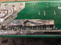
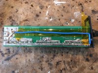
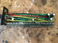
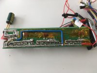
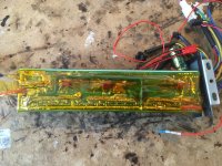
4. How to seriously upgrade traces
5. How to calibrate cal a

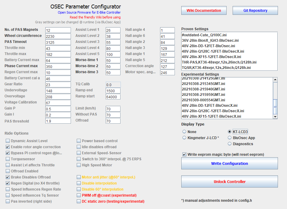
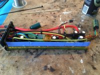
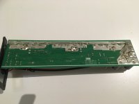
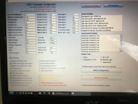
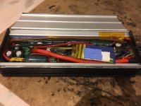
I will add some screenshots of the hard and software settings of the second square wave controller that I optimized with mods and custom firmware:
 

Attachments

  • 0476D0BA-6B29-45A3-BA89-B068F0BF9D92.jpeg
    0476D0BA-6B29-45A3-BA89-B068F0BF9D92.jpeg
    209.5 KB · Views: 1,068
  • BE1DB566-E120-4DFF-A2B6-133988569B98.jpeg
    BE1DB566-E120-4DFF-A2B6-133988569B98.jpeg
    229.9 KB · Views: 1,066
  • 1E815CDF-53C8-40B3-85B0-08192C3E8EFD.jpeg
    1E815CDF-53C8-40B3-85B0-08192C3E8EFD.jpeg
    308.3 KB · Views: 1,066
  • 3E1E5239-6DCB-4205-AEC9-4B90FF13B994.jpeg
    3E1E5239-6DCB-4205-AEC9-4B90FF13B994.jpeg
    285.8 KB · Views: 1,065
  • AE4EC0FD-A4DC-4F84-931E-24FF55E23826.jpeg
    AE4EC0FD-A4DC-4F84-931E-24FF55E23826.jpeg
    385.3 KB · Views: 1,065
  • 0D1EB6C3-A3D4-40AE-948F-249FE508A98A.jpeg
    0D1EB6C3-A3D4-40AE-948F-249FE508A98A.jpeg
    286.7 KB · Views: 1,065
  • 459D37A7-B42A-4196-AB0E-5908E1A9C5A1.jpeg
    459D37A7-B42A-4196-AB0E-5908E1A9C5A1.jpeg
    390.5 KB · Views: 1,066
  • 90C458EA-B9BB-4480-AB63-78A6E0969C38.jpeg
    90C458EA-B9BB-4480-AB63-78A6E0969C38.jpeg
    471.8 KB · Views: 1,065
  • 03613939-CEF3-4432-B1D5-771C36259780.jpeg
    03613939-CEF3-4432-B1D5-771C36259780.jpeg
    320.1 KB · Views: 1,065
  • 500B8934-CBB3-47C5-9359-FEA5D74F5E9F.jpeg
    500B8934-CBB3-47C5-9359-FEA5D74F5E9F.jpeg
    311 KB · Views: 1,067
  • 62E3653D-7DD8-4661-8CFB-9417CBEEB319.jpeg
    62E3653D-7DD8-4661-8CFB-9417CBEEB319.jpeg
    500.2 KB · Views: 1,068
  • 67EC6E0D-DA0E-4AF4-9C1A-6987AD593D67.jpeg
    67EC6E0D-DA0E-4AF4-9C1A-6987AD593D67.jpeg
    259.9 KB · Views: 1,067
  • 604E1FC3-4A74-4DD8-8567-D3169627C0BD.jpeg
    604E1FC3-4A74-4DD8-8567-D3169627C0BD.jpeg
    559.1 KB · Views: 1,067
  • FB0BEBE1-34CC-40BE-8DE0-4604F94A7D28.jpeg
    FB0BEBE1-34CC-40BE-8DE0-4604F94A7D28.jpeg
    372.2 KB · Views: 1,066
Wow that's some accurate feedback.

Whats the purpose of the thick blue wire?
Do you recommend beefing UP the traces for my configuration? 18fet controller ; max AMP battery 50A, max motor phase 130A, 67V.
 
atkforever said:
Wow that's some accurate feedback.

Whats the purpose of the thick blue wire?
Do you recommend beefing UP the traces for my configuration? 18fet controller ; max AMP battery 50A, max motor phase 130A, 67V.

The purpose of the thick blue wire is to beef up the positive (+) bus bar for the power supply even more, beyond the maximum space that is available on the normal location of the bus bar. You can only thicken that trace to the point where it starts to hit the case and can create a short cut. Also, it provides power to the very end of the trace, so that all mosfets have ‘access’ to an equal amount of volts and amps: the bus bar is fed from two sides now.

The thick brown wire at the upper side that runs along the mosfets has the same function, but in this case for the minus (-) bus bar. I was just thinking like following water flow and making sure all amps are balanced across the pcb.

In your case I would say beefing up should not strictly be necessary, because the 72v version of the 18 fet controller has the same traces and is already rated for 60 amps peak.

That being said, it is quite easy to just melt some more solder along the main bus bars and maybe also thicken the bar for the three phases. I would recommended to cool the mosfets with some soaking wet toilet paper (water ;) ) to make sure they don’t overheat. Use a high power solder iron (60 - 100 watt) to quickly melt the solder and then quickly cool again. And don’t go over the white lines on the side, otherwise you could risk hitting the metal casing when assembling the parts again.

Adding uprated 8 awg wires was a lot of work because of the limited space and the large amounts of heat and solder that you need to properly attach these. So I would not recommend changing the default power supply cables unless you really want to push the limits.

Hope this helps?
 
Vbruun said:
That i am not sure if voltage divider would help. Can you describe how are powering the T9? Are you disconnecting the battery with a connector or maybe a switch? Those small DC/DC converters are not really good in protecting against voltage spikes and that also could be the reason to kill the sensor.
 
Yep but adding a second power feeding wire modifies the current flow direction on the mosfet bus and current density, hence my question. I havnt the knowledge to say if it has an impact on the performance or safety but it seems that you studied the thing a lot so it's probably fine.
 
Well I didn’t do any transient simulations or something like that. But I figured that as all phases have their own large capacitor, they all have access to the same instantaneous 60v anyway without any time delays. So feeding the bus bars from two sides should have no effect on the timings, only a positive effect on the local voltage drop. Of course the proof of the pudding is in the eating. So far these modified controllers seem to handle the 80/300 amps just fine and are extremely quiet in operation (much more quiet than my FOC MQCON / sabvoton 72150 for example).
 
Funny; I'm also leaving sabvoton for KT ;)

Do you have more torque with rotor angle correction enabled (FOC) rather than pure sine?
 
szkuba said:
Vbruun said:
That i am not sure if voltage divider would help. Can you describe how are powering the T9? Are you disconnecting the battery with a connector or maybe a switch? Those small DC/DC converters are not really good in protecting against voltage spikes and that also could be the reason to kill the sensor.

I was planning to install an erider torque sensor as well but reading this makes me hesitant. Is there a torque sensor that people have good experiences with in combination with the kt controllers? Is a Sempu T4 a better choice than the erider with respect to failing over time? Or am I understanding this issue the wrong way..? What is the best torque sensor to use with a modified kt controller on the X4 input?
 
atkforever said:
Funny; I'm also leaving sabvoton for KT ;)

Do you have more torque with rotor angle correction enabled (FOC) rather than pure sine?

Great to share experiences then!

I need to do much more testing and especially measuring with the different wave forms. I don’t know about the difference in torque yet (need to measure acceleration), but right know my choice was primarily based on sound. It did not feel slower yet but of course I need to measure. I will do that while measuring the performance difference of adding different types of ferrofluid to the dd motor as well. I am in direct contact with the manufacturer to do some in-depth testing of their ferrofluids. Hope to get a bunch of samples soon!

I do also use the sabvoton/MQCON in my other ebike; that one is a beast with the 130 amps and 350 phase amps that I set it to right now (I don’t dare go any higher with my 8 awg cables and poor 10p Samsung 29e 18650 cells..). But it was quite expensive with the Additional costs for a cycle analyst v3. The total bike weighs 60 kg (72v 29ah battery) so Is approaching a small motorcycle more or less.

So right now I’m trying to approach (or even exceed..) that performance by building a very lightweight carbon mtb with modified kt controller and 72v 5 ah lipo battery packs. With a 5 kW (rated) hub motor + ferrofluid that thing should become a beast as well ;)
 
Back
Top