Car alternator to PMAC?

j bjork

100 kW
Joined
Aug 31, 2018
Messages
1,992
Location
Linköping, Sweden
A little side project..

Mostly just for fun I want to convert a (or a few) alternators.
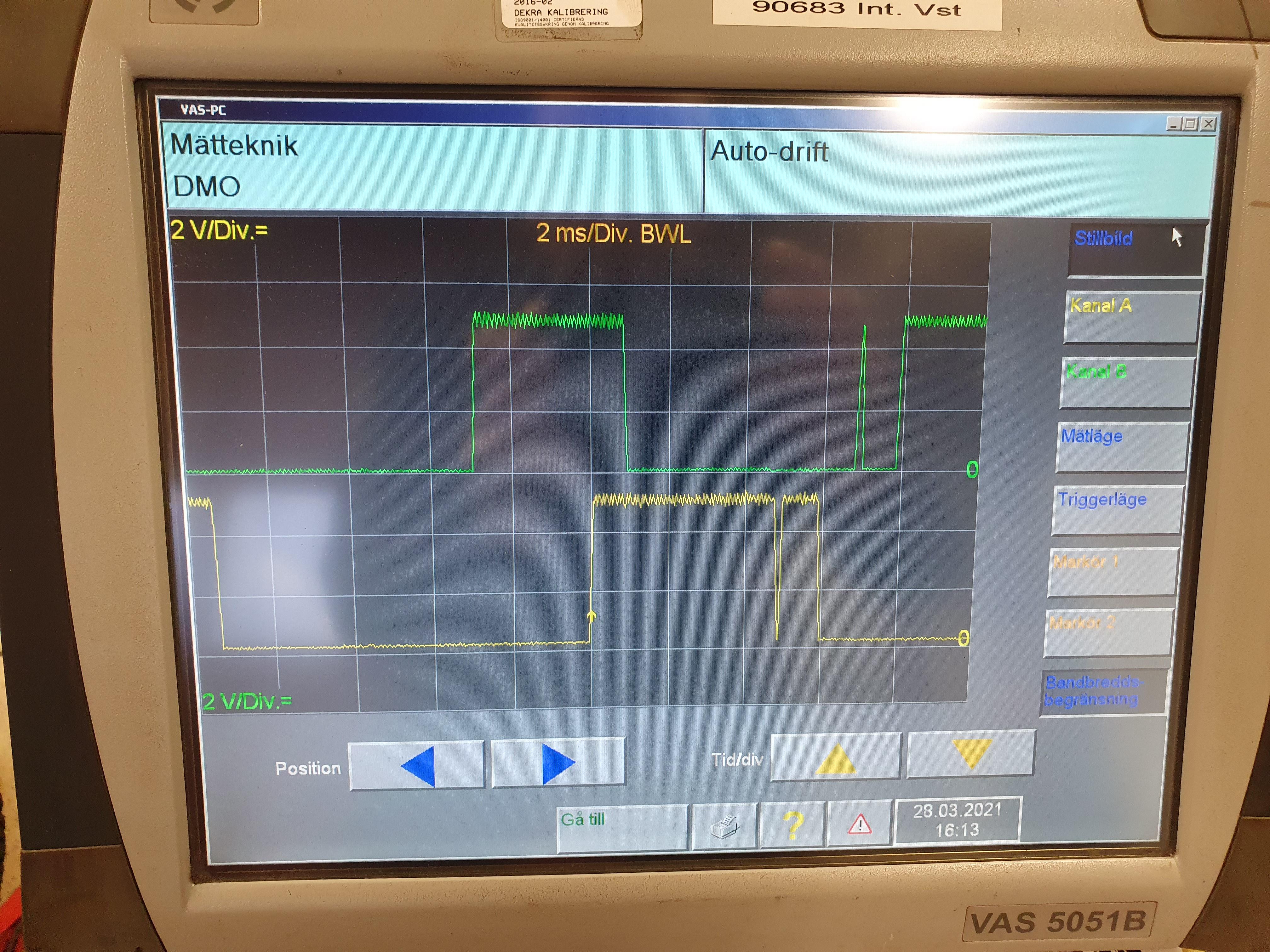
I first made an easy conversion that I played with a little on a Bosch 140A:

RiusyUE.jpg


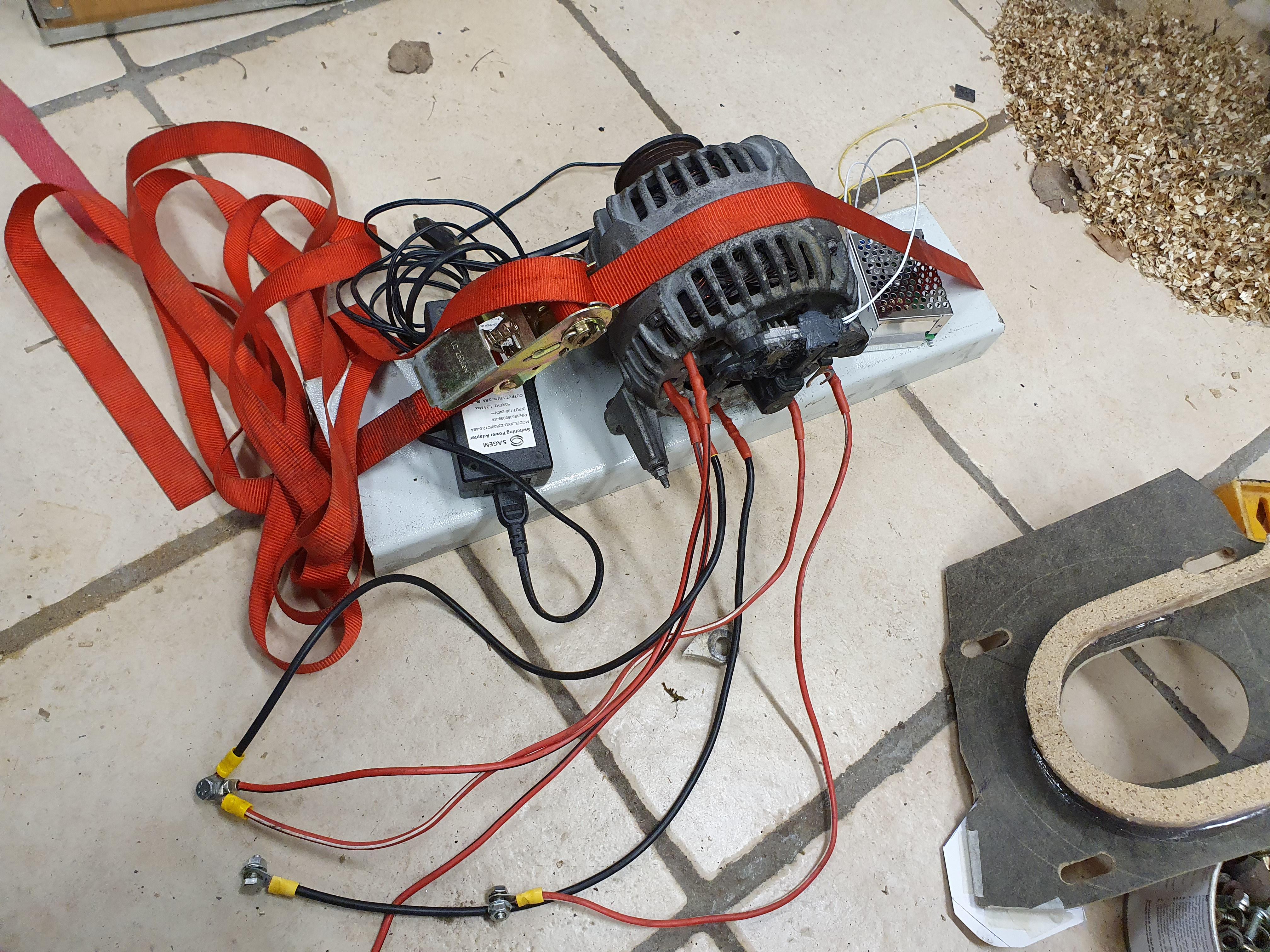
I tested a little in delta and Wye, but it is annoying to need power to the field winding and to run sensorless..

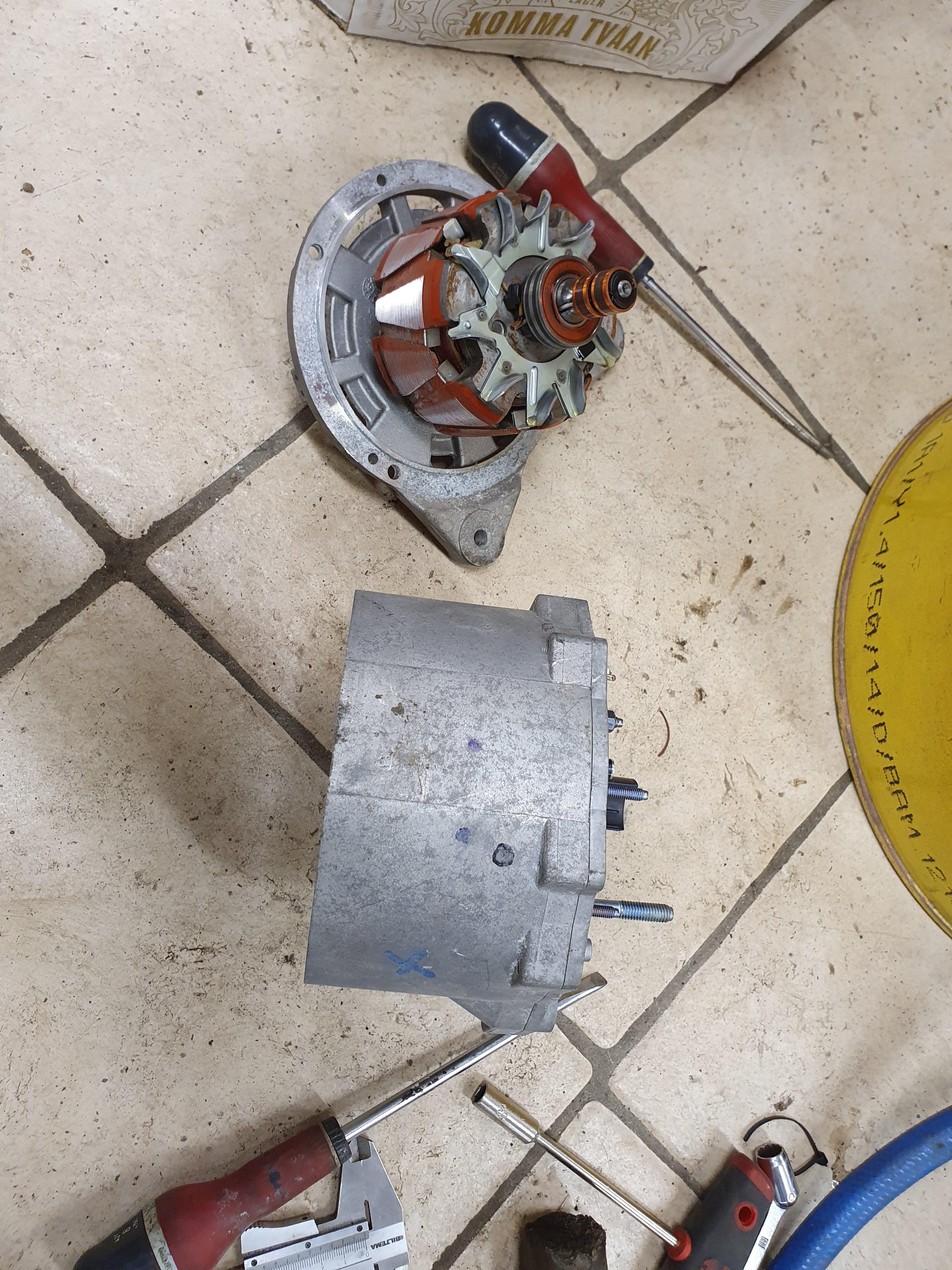
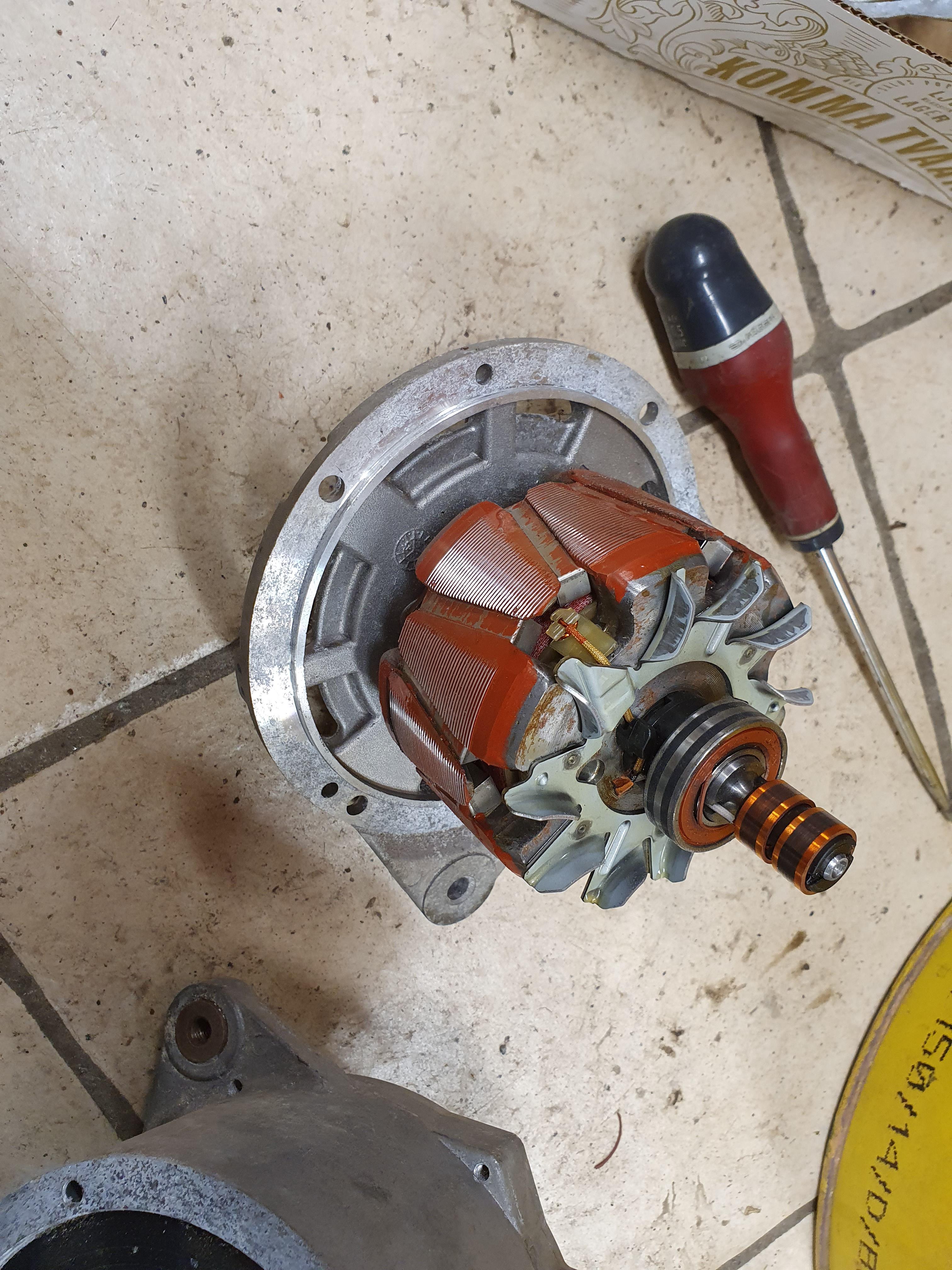
I took apart a valeo 120A alternator with a broken field winding, and tried to take the rotor apart. I eventually got it apart, but damaged.

xP61l83.jpg


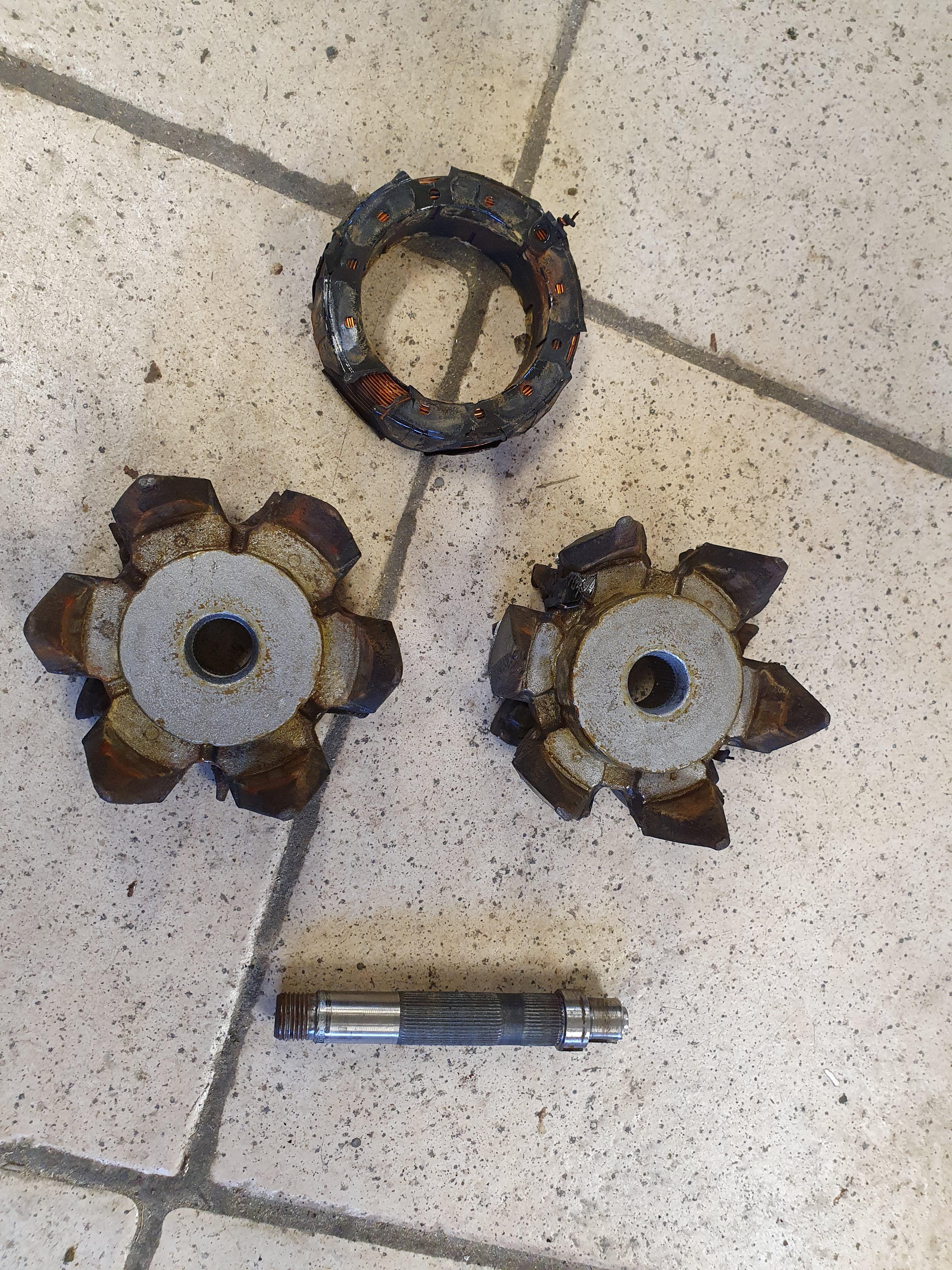
I have one more, and now I can take it apart without damage.
The plan is to replace the winding with a magnet. To fit it should be 83mm dia, 60mm hole and 30mm thick.
I found a ferrite magnet that is 80x40x15, pulling force 9,5kg. I could stack 2 of them to get 30mm and take off some material on the rotor claws to fit the center hole on the magnets.
Would that work, or do I need stronger magnets?

I would like to use Bosch alternators, they seem to be better.
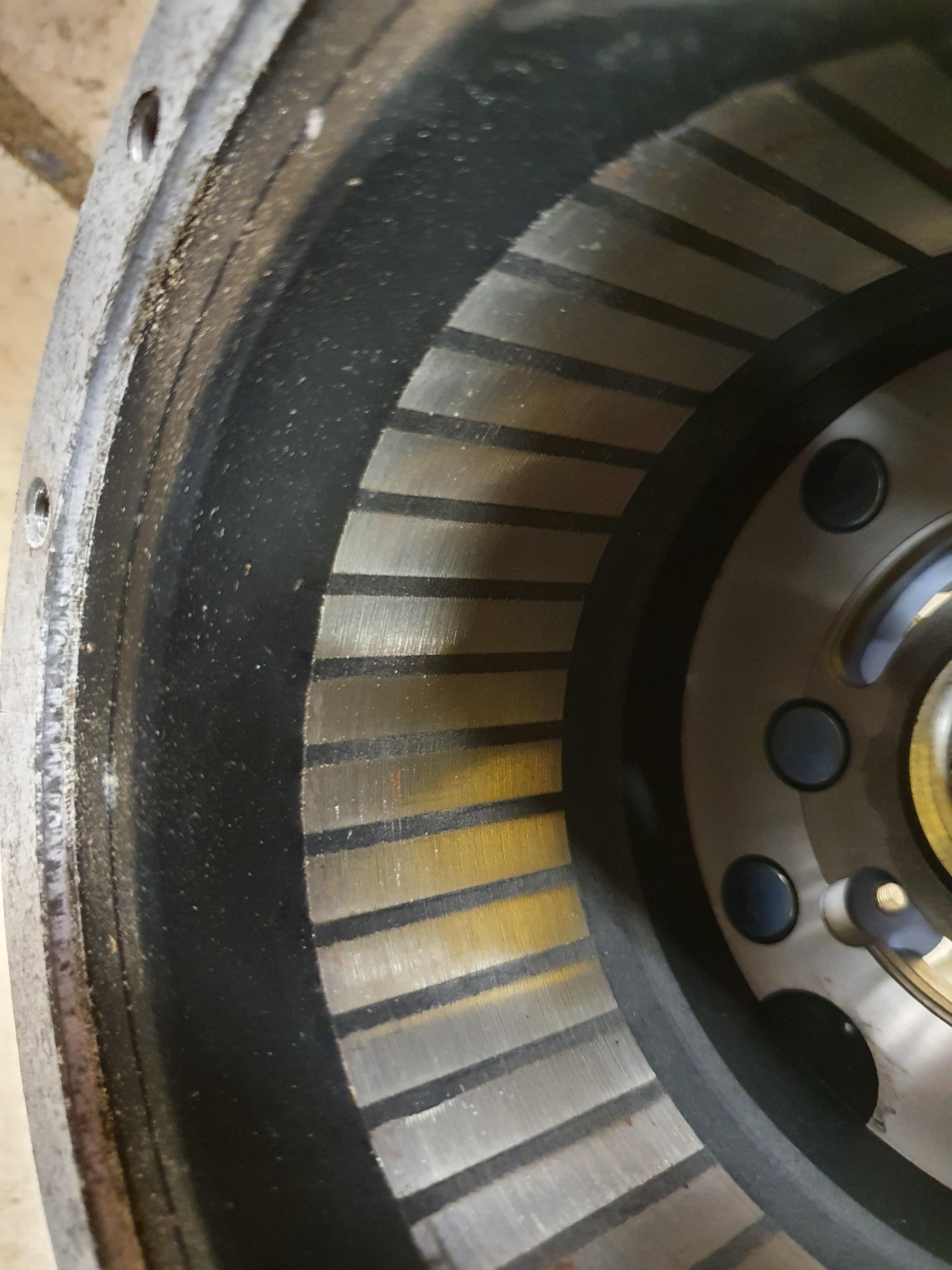
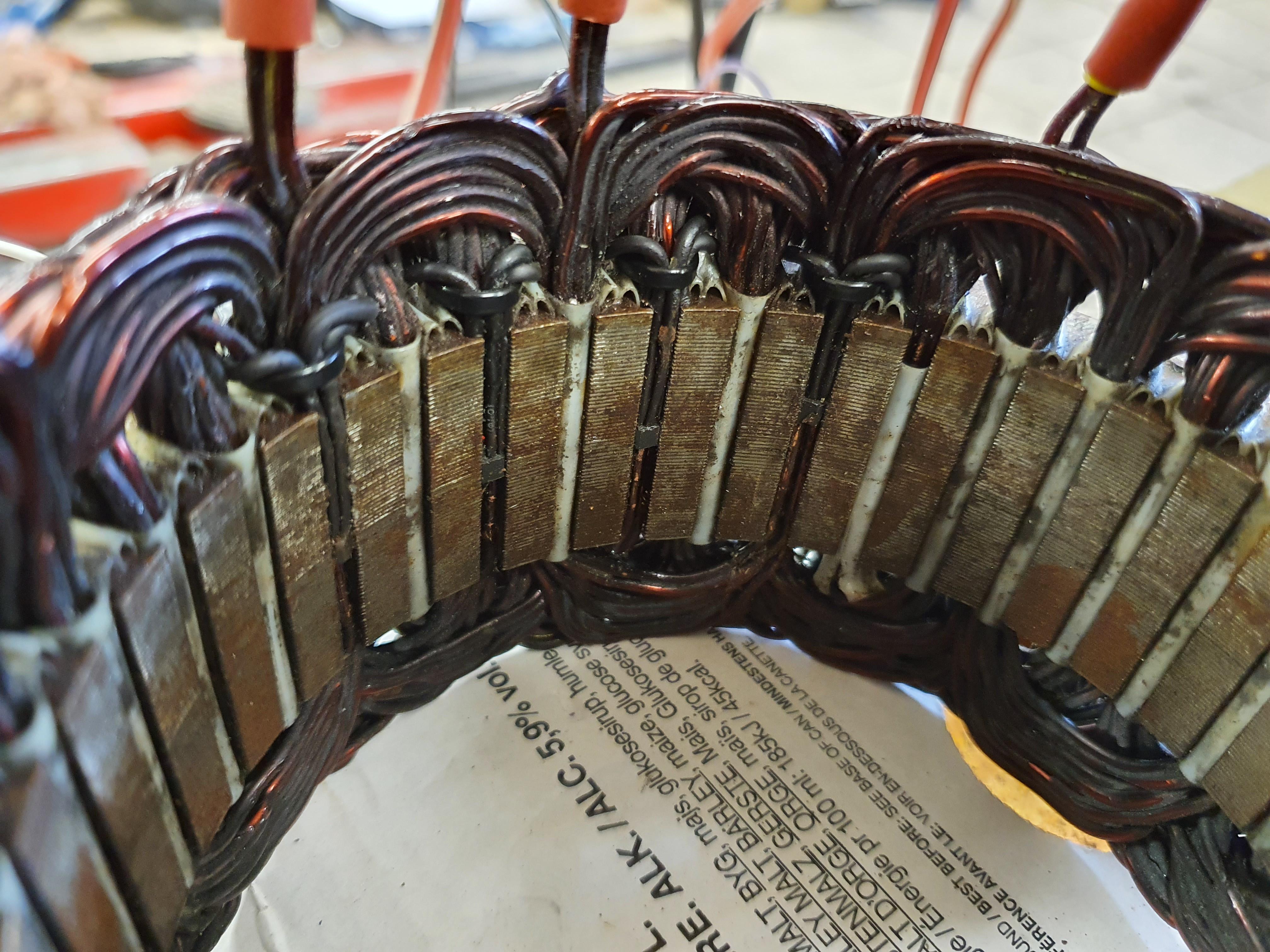
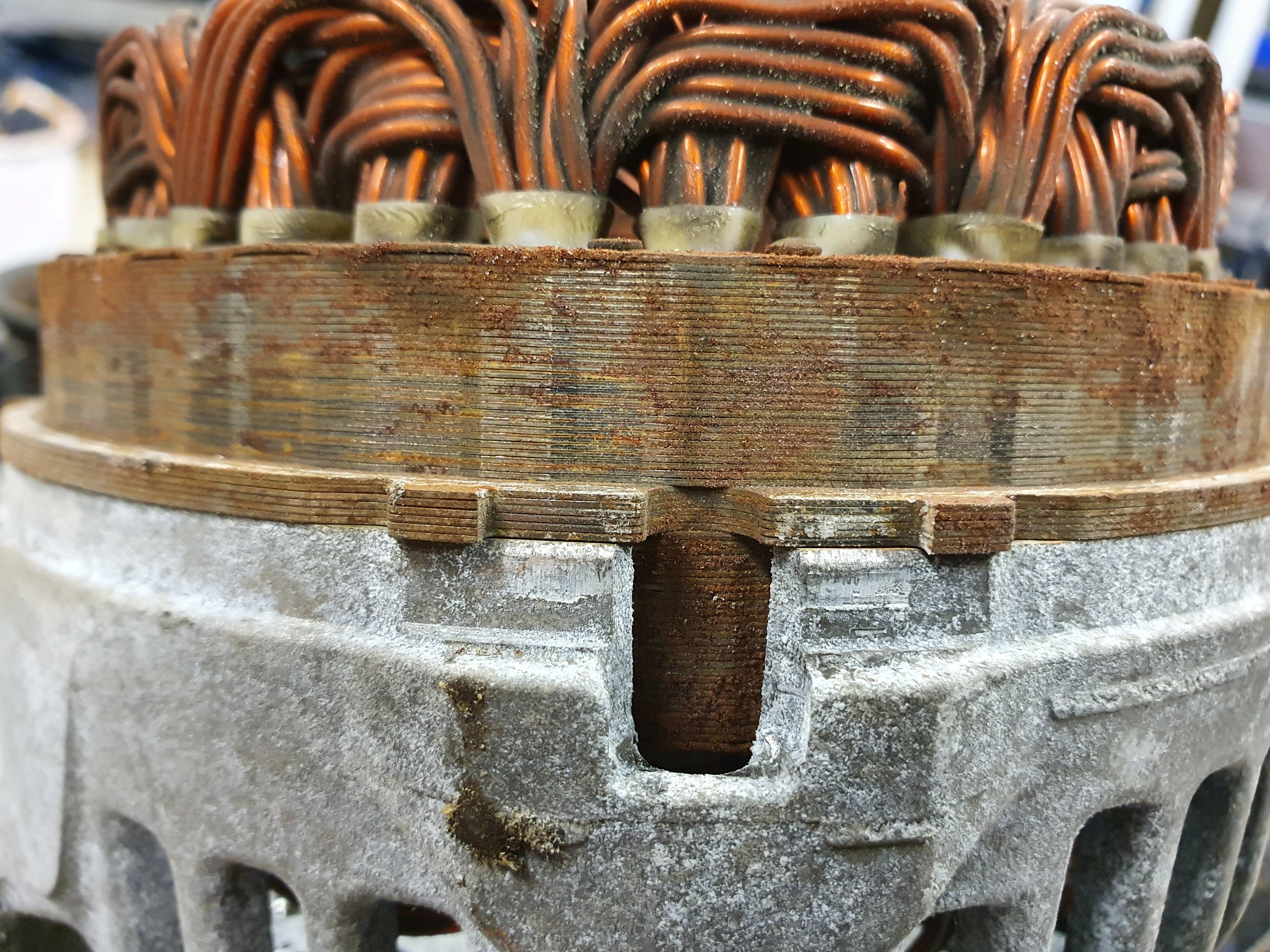
Valeo laminations:

XhUy6Uh.jpg


Bosch laminations:

k2JHgYj.jpg


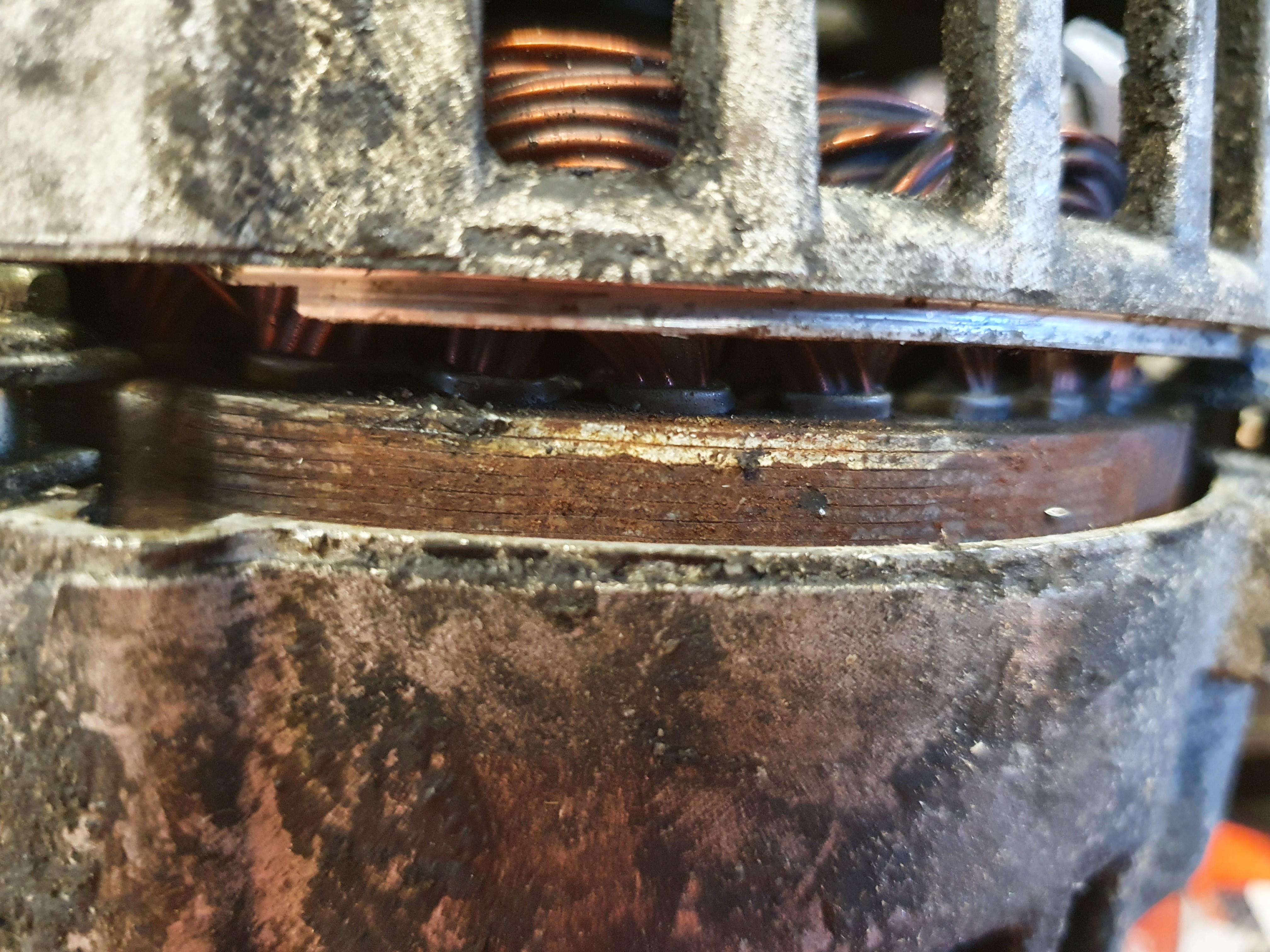
But so far I have not been able to take the bosch rotor apart:

J48D4ka.jpg


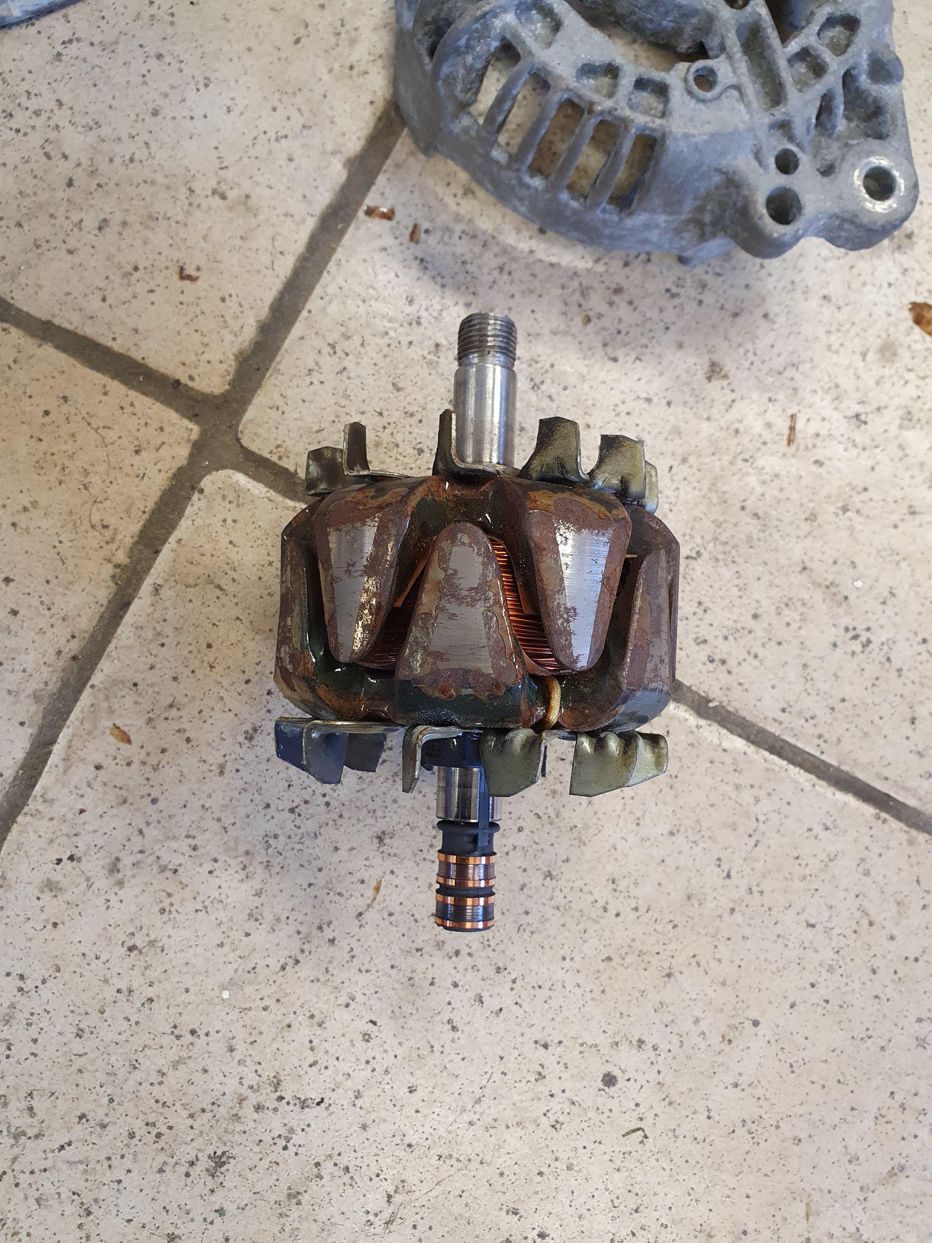
I have tried to press out the shaft in either direction, but so far no movement.
I havent tried to pull one half at a time. I tried that with a puller on the valeo, but the only thing that led to was damaging the rotor.
On the valeo rotor I eventually could press out the shaft from the rotor by pressing on the pulley side on the shaft. But that dont seem to work on the Bosch.
If someone knows how, I am interested. Otherwise I guess I take another bosch rotor and beat on till something gives, so I can find how it should be done.
 
If you haven't already, you might want to read around the forum for altermotor and/or alternator. There's a number of threads that may have useful info for you.
 
I have been going trough some threads, but none of them use permanent magnets.
I know there should be at least one, where they built a new rotor. But I havent found that so far, and I dont think it matters much because it is different.
I want to use the original rotor with a permanent magnet.
But I hesitate when I found out what strong magnets in these sizes cost :shock:

A link to another thread:
https://endless-sphere.com/forums/viewtopic.php?f=7&t=105734&p=1547454&hilit=altermotor#p1547454

buick lacrosse e-assist (interesting link in the link by Amberwolf)
https://endless-sphere.com/forums/viewtopic.php?f=30&t=110673&p=1621772&hilit=alternator#p1621772

A long thread:
https://endless-sphere.com/forums/viewtopic.php?f=30&t=60910

https://endless-sphere.com/forums/viewtopic.php?f=30&t=16328&hilit=widodo

Short, but a little interesting:
https://endless-sphere.com/forums/viewtopic.php?f=30&t=61343&p=916424&hilit=altermotor#p916424

A video mounting a magnet:
https://www.youtube.com/watch?v=MPY2JKwDNfY

https://www.youtube.com/watch?v=vp44tW1VDGg

(I plan to post more links later)
 
j bjork said:
I have been going trough some threads, but none of them use permanent magnets.
I know there should be at least one, where they built a new rotor. But I havent found that so far, and I dont think it matters much because it is different.
I want to use the original rotor with a permanent magnet.
But I hesitate when I found out what strong magnets in these sizes cost :shock:

I don't remember seeing people here with PM alternators, only some users on YT, like Chris workshop, Austiwawa, and others
Please check them for ideas
 
I did something like that many years ago to build a hydroelectric generator. I used some old ceramic speaker magnets that took up the space of the original field coil. One thing I found is the original shaft is magnetic, which shunted away most of the magnetic field. I had to make a non-magnetic shaft from stainless steel. After that it worked reasonably well until the bearings rusted out. But the ceramic magnets are really too weak to make a decent motor. And they get easily demagnetized by high currents.

That was before neodymium magnets were affordable. Now what I see people do is use multiple smaller magnets in a ring around the shaft. Get the right length so the rotor halves are the right spacing. On yours, there is a cylindrical core around the shaft that would have to be removed to make room for the magnets. On mine it was a separate piece that came out with the field coil. You'd still have the issue with the shaft being magnetic.

The skewed "claws" aren't optimal for a motor but should make it a bit quieter.
 
ShadowNightmares said:
I don't remember seeing people here with PM alternators, only some users on YT, like Chris workshop, Austiwawa, and others
Please check them for ideas

Thanks, I havent seen the one from Chris workshop: I guess I will have to look a bit more. I have seen the one from Austiwawa, and another similar setup. I have posted links to both.


Thanks, interesting.. The magnetic shaft problem should be the same with the electromagnet I suppose?
Making a new shaft is a bit bigger task then I planned for this project.
But then it would be possible to make it longer, and maybe with splines or at least keyed in the end for a sprocket or pulley.
The problem is that I cant make the splines for the rotor (or for a sprocket) myself.

In that case it might as well be worth to consider making a new rotor, IPM altermotor :wink:

Im not sure I understand what you meant with that people use multiple smaller magnets?
Do you mean thinner ring magnets with the right dia, and stack several to the right thickness?
Or something like several small rods and arrange them in a circle?
I think it has to be difficult to get them to stay in place in that case, but I guess it should be possible to mill small pockets to put them in.
 
j bjork said:
This one might be something to work on in that case:

OrYHbuG.jpg


WQunn8k.jpg


rtj6ouX.jpg


It is a hitachi water cooled alternator, seems to be 190A 14V
Very thin laminations


This watercooled 190Amp alternator is similar to the ones i mentioned, still an alternator but with small magnets between the claw poles.
If you really want a "full" PM rotor, check the Chris workshop video
 
j bjork said:
Thanks, interesting.. The magnetic shaft problem should be the same with the electromagnet I suppose?
Making a new shaft is a bit bigger task then I planned for this project.
But then it would be possible to make it longer, and maybe with splines or at least keyed in the end for a sprocket or pulley.
The problem is that I cant make the splines for the rotor (or for a sprocket) myself.

In that case it might as well be worth to consider making a new rotor, IPM altermotor :wink:

Im not sure I understand what you meant with that people use multiple smaller magnets?
Do you mean thinner ring magnets with the right dia, and stack several to the right thickness?
Or something like several small rods and arrange them in a circle?
I think it has to be difficult to get them to stay in place in that case, but I guess it should be possible to mill small pockets to put them in.
The magnetic shaft is not a problem for the stock electromagnet as this becomes part of the core, which is also magnetic.

I don't have a picture, but I was thinking cylinder magnets arranged in a circle. Yes, they will repel each other strongly so you glue them one at a time with clamps to hold them in place while the glue hardens. Machining a recess for the ends will help a lot. You also need to space them carefully to maintain decent balance.

The IPM rotor in the picture with bar magnets between the claws looks like it would work well too. I see it also has a field winding so you could implement field weakening easily.
 
ShadowNightmares said:
This watercooled 190Amp alternator is similar to the ones i mentioned, still an alternator but with small magnets between the claw poles.
If you really want a "full" PM rotor, check the Chris workshop video

I found the videos, very interesting.
To bad they are in french, I only understand half of what he says even with translation.
I thought the plastic rotor was just a test, and that he would do a metal one after.
But I cant find a video when he does.

Interesting with the optical sensors on a wheel were the brushes would normally sit.
I was thinking about something similar, but my plan was to use a magnet wheel for a pas sensor and hall sensors.
 
fechter said:
The IPM rotor in the picture with bar magnets between the claws looks like it would work well too. I see it also has a field winding so you could implement field weakening easily.

What I meant with ipm rotor was to make a new rotor with magnets in a V configuration, but I guess that also counts as ipm.
And a modified rotor with one or more magnets around the shaft too.

I tested that alternator as a motor too, and those magnets are too weak for it to even run steady without help from the field winding.

With the cost of magnets it seems a bit much for now, when I dont really have a use for the motor. So I think I will just focus on hall sensors for now.
As I still have the brushes for the field winding it will be difficult to have something external, so I am looking at mounting them in the slots on the stator.
I have been reading here: http://mitrocketscience.blogspot.com/2011/08/hall-effect-sensor-placement-for.html

There are 36slots, so that means they are 10 mechanical degrees apart.
And there are 6 pole pares on the rotor.
Then it seems like I can mount the sensors 20degrees apart, so that would mean every other slot.
The problem then is witch slots to choose..
As far as I understand it dosent say much about how th get the timing right.
It does say to watch the winding scheme to determine the polarity of the slot.
 
j bjork said:
I have been reading here: http://mitrocketscience.blogspot.com/2011/08/hall-effect-sensor-placement-for.html

There are 36slots, so that means they are 10 mechanical degrees apart.
And there are 6 pole pares on the rotor.
Then it seems like I can mount the sensors 20degrees apart, so that would mean every other slot.
The problem then is witch slots to choose..
As far as I understand it dosent say much about how th get the timing right.
It does say to watch the winding scheme to determine the polarity of the slot.

Please check equations 3 and 4 on the page, they will help with hall sensor position, but since the rotor poles are wedge/claw shaped, you need to put the sensors in the middle of the stator
 
From what I understand I can calculate first the minimum spacing between the halls, then if that dosent fit I can calculate other spacings that will work too. But not the actual position?

As I have 36slots we can call them 1 to 36. So I should get the right spacing if I mount them in slot 1, 3 and 5. But also in 2, 4 and 6, or 3, 5, 7,and so on. But do I get the same result? I am thinking I should get different timing in the uneven vs even numbers.

Edit, I looked at this video: https://www.youtube.com/watch?v=rQy-hIMY__A
He dont seem to bother with the winding scheme or timing other than to get the spacing right.
So I think I will try that too. It looks difficult to follow the winding and see how it is done.
I had an idea of putting dc voltage trough one winding at the time, and try to determine what slots gets magnetic and with what polarity. Maybe worth a try.
 
The hall sensors arrived:

tvcTHs8.jpg


41F, a picture dosent really show how tiny they are.
I knew the measurements, but was still surprised when I saw them.
But being small didnt mean it was easy to mount them..

XTJOnv1.jpg


I removed the top plastic insulator over the windings in the slots, and pressed on small rods in the slots, pried with small screwdrivers etc. to make room to be able to slide in the sensors.
The two in the middle are pretty good in position I think.
The one to the right is a little tilted and not all the way down to the middle in the slot.
I started with 12 sensors, but when I got this far I had broken a few. I decided to leave it and start with the one to the left instead.
As you can see that one is pretty badly tilted.
I am down to two extra sensors now.. I tested these I have mounted, and they all worked. I then decided to try it.


I have ran it with a nucular, motor setup works fine. It starts fine from standstill, runs smooth in both high and low rpm. But if I am quick on the throttle it seems to loose sync. It jerks and makes noises. I dont get any fault when it happens.
I think it is the higher currents or magnetic field in the stator that affect the hall sensors.

*Would getting a third sensor in a better position than the one to the right or left make a difference?

*The wiring from the sensors. It is very tight, and if i run it under the windings it hits the fan on the rotor. I wasent able to run all 3 wires through one slot, so I ran two on one side and one to the other side. It just happened to be the + and - to one side, and signal to the other. Should I try to run the - and signal together instead, maybe try to twist them a little if possible? You can see the wiring from the sensors in the picture.

*Is it just too much interference from the lamination's so close to the face of the sensors even if I get them perfectly strait?

*I dont have anything "extra" in the wiring now, should I add resistors or capacitors?
 
j bjork said:
I had an idea of putting dc voltage trough one winding at the time, and try to determine what slots gets magnetic and with what polarity. Maybe worth a try.

That's the proper way to do it. You need enough current to get the rotor lined up solidly. Once the rotor locks into position, the proper hall location is going to be right where it's on the spot where it toggles. Moving the rotor very slightly either way from the locked position should make the hall toggle. It can be anywhere on the stator as long as it's at the toggle point. Repeat the process for the other combinations of the phase wires.
 
j bjork said:
*Would getting a third sensor in a better position than the one to the right or left make a difference?

Yeah, you NEED 3 sensors, and its better to keep them at the same level in the middle
Check Austiwawa's Channel for a hall tester schematic, so that you will know if the sensors are working as they should, then after comparing your LED signals with his, then you can test on the controller
 
fechter said:
j bjork said:
I had an idea of putting dc voltage trough one winding at the time, and try to determine what slots gets magnetic and with what polarity. Maybe worth a try.

That's the proper way to do it. You need enough current to get the rotor lined up solidly. Once the rotor locks into position, the proper hall location is going to be right where it's on the spot where it toggles. Moving the rotor very slightly either way from the locked position should make the hall toggle. It can be anywhere on the stator as long as it's at the toggle point. Repeat the process for the other combinations of the phase wires.

I found a way to put about 25A trough one phase at a time. The rotor dosent really lock in a position, I can move it easy a little in each direction. And in that little movement one led on my tester turns on and off for each phase.
So I guess that means the positions should be ok, but I think I should get an oscilloscope and look at the signals.
Maybe I can determine if one or all go bad under load, or what the problem is.
 
j bjork said:
I found a way to put about 25A trough one phase at a time. The rotor dosent really lock in a position, I can move it easy a little in each direction. And in that little movement one led on my tester turns on and off for each phase.
So I guess that means the positions should be ok, but I think I should get an oscilloscope and look at the signals.
Maybe I can determine if one or all go bad under load, or what the problem is.

It sounds like you have the position correct. They should be close enough for the motor to run.

With the 25A running, you can also see how hard it is to turn the rotor past the cogging point. You want it to be pretty hard.
 
I didnt really test how hard it was to turn further, but it sure was pretty hard.
I tested what the signals looked like on an oscilloscope.
I made some tests paralleled with my tester with 10kohm pull up resistors, there was some disturbance but not too bad.
Then i tested with the sensors connected to the nucular instead. That cleaned up most of the disturbance and looked pretty good as far as I can tell:

RNOiHCL.jpg


After some tests I found what I think is the problem:

YuW0YiC.jpg


This is when I hit the throttle fast, and even then it was not very easy to catch.
It is from the green wire, that is one of the sensors that is in a good position.

I wonder if this may be that I put it in a slot with reversed polarity?
So the magnetic field in the stator activates the sensor on higher phase amps?
 
Not good. Capacitors won't fix that problem. The flux it getting pulled to one side at high currents. Most motors have the hall sensors mounted at the end of the slot, not in the middle. Since the rotor teeth are skewed, this might be hard to make work also. You may need to use a separate encoder, either optical or magnetic or use a sensorless controller.
 
fechter said:
Not good. Capacitors won't fix that problem. The flux it getting pulled to one side at high currents. Most motors have the hall sensors mounted at the end of the slot, not in the middle. Since the rotor teeth are skewed, this might be hard to make work also. You may need to use a separate encoder, either optical or magnetic or use a sensorless controller.

I am in no means an expert in magnetic fields, oscilliscope uses and other stuff. But i wonder if you're feeding the rotor backwards. One of the alternators OP showed us had ferrite magnets between the teeth, maybe with the reverse polarity on the field coil could be messing with the hall sensors
 
Thanks, it would be hard to add an external encoder as long as I use the electro magnet.
If I change to permanent magnet that would be a lot easier, then I would have the unused end of the shaft where the brushes was.
I havent seen this problem on the sensor with light green wire (wire colors are just for my own memory :wink: )

Edit, found the problem on that signal too:

JkT9ZCO.jpg


The green curve, it just goes high instead of low when it happens it seems.

Maybe one option would be to use only that sensor of the ones I have, and calculate another spacing for the other sensors to get them in other slots?
Or maybe I just havent seen it in the signal from that sensor.. I could try more to make more or less sure, but I am a little worried that it might be damaging to the controller :? I wouldn't want to blow the nuc on this little side project. I have a cheap controller to test on too, but it is way too weak to run in to this problem.

The rotor with magnets is for the water cooled alternator, this one is a "normal" with only electro magnet.
I tested to change the polarity on the rotor anyway, with no obvious difference.
I was expecting it to change direction, but not even that happened.
 
Back
Top