TSDZ2 EBike wireless standard (like Specialized Turbo Levo) - OpenSource

@frzoen,

Your current design will not work and will probably damage the NRF module.
You can't use an N channel FET in the way you are intending.
An N channel FET is turned on when its gate is a few volts above its source.
In your schematic the source is connected to Vbat so to turn on the FET the output of the NRF would need to rise to Vbat + 3V.
It obviously can not do this and because the FET Gate will be reverse biased it will probably apply Vbat to the NRF pin and blow it.

You need to use a circuit similar to the original design with two devices. However it doesn't really need the high side switch IC, that could easily be replaced with a small P channel FET and a resistor.
 
g4eml said:
@frzoen,

Your current design will not work and will probably damage the NRF module.
You can't use an N channel FET in the way you are intending.
An N channel FET is turned on when its gate is a few volts above its source.
In your schematic the source is connected to Vbat so to turn on the FET the output of the NRF would need to rise to Vbat + 3V.
It obviously can not do this and because the FET Gate will be reverse biased it will probably apply Vbat to the NRF pin and blow it.

You need to use a circuit similar to the original design with two devices. However it doesn't really need the high side switch IC, that could easily be replaced with a small P channel FET and a resistor.

Hi g4eml!

Totally agree. I feel dum dum right now. My brain went on vacation i think. :?
There is some confusion in schematic... Visible part is of course SSM6K361NU which is indeed N FET (same as symbol) but value for it is SSM6J507NU (P FET...) ... that cannot work in this configuration. Horror.
Thanks for saving my mind while troubleshooting. :bigthumb:
Right now TSDZ2_VIN is connected to the V_BATT via resistor and behind this resistor sits SSM6K361NU (N FET) that can short TSDZ2_VIN to ground. I feel like this is a quick fix for this situation (and ordered parts, PCB's i had to reorder :roll: ).

Additionally I'm thinking about switching to optocoupler as a switch. This would prevent from getting V_BATT to the pin of the NRF if anything goes wrong. Do You like this idea?
 
Frzoen said:
g4eml said:
@frzoen,

Your current design will not work and will probably damage the NRF module.
You can't use an N channel FET in the way you are intending.
An N channel FET is turned on when its gate is a few volts above its source.
In your schematic the source is connected to Vbat so to turn on the FET the output of the NRF would need to rise to Vbat + 3V.
It obviously can not do this and because the FET Gate will be reverse biased it will probably apply Vbat to the NRF pin and blow it.

You need to use a circuit similar to the original design with two devices. However it doesn't really need the high side switch IC, that could easily be replaced with a small P channel FET and a resistor.

Hi g4eml!

Totally agree. I feel dum dum right now. My brain went on vacation i think. :?
There is some confusion in schematic... Visible part is of course SSM6K361NU which is indeed N FET (same as symbol) but value for it is SSM6J507NU (P FET...) ... that cannot work in this configuration. Horror.
Thanks for saving my mind while troubleshooting. :bigthumb:
Right now TSDZ2_VIN is connected to the V_BATT via resistor and behind this resistor sits SSM6K361NU (N FET) that can short TSDZ2_VIN to ground. I feel like this is a quick fix for this situation (and ordered parts, PCB's i had to reorder :roll: ).

Additionally I'm thinking about switching to optocoupler as a switch. This would prevent from getting V_BATT to the pin of the NRF if anything goes wrong. Do You like this idea?

beemac said:
Hey @frzoen - how are you only using one mosfet? I originally questioned why we were using two - but i realised when I was testing that having just one exposed the vbatt voltage to the nrf pin - that's why (i believe) we have the low side bsp296 mosfet exposed to the nrf (so it only sees gnd, not 48-60v) controlling the high side 4140... how do you get around that with only one?

Nice to know I wasn't talking gibberish.... :)

Why not use the circuit we've tested that works using the BSP296 and 4140N - isn't the issue you've just discovered another reason for that? The circuit has probably only been built by tens of people but has been tested for probably hundreds of hours now and works - what is the benefit in the change you propose? Not against change - but why throw away many hours of testing?
 
As Beemac suggests the BSP296 and 4140N combination has been proved to work. The only drawback is the large physical size of the components, making a small PCB difficult to lay out. So I can see a good reason for replacing them. I think they were probably chosen to make breadboard assembly easier. I am sure that the same thing could be achieved with smaller devices. The 4140N could easily be replaced with a P channel FET and a couple of resistors and there are plenty of N channel FETS in SOT23 packages with high enough voltage rating.

Your idea of using a N type FET to short out the Vin voltage after a resistor might work if the current requirement of the Vin signal is low enough but it would invert the ON/OFF logic and so would need a firmware change. Going for extra complexity with opto-couplers is not really necessary. The two device solution protects the NRF module well enough.
 
g4eml said:
As Beemac suggests the BSP296 and 4140N combination has been proved to work. The only drawback is the large physical size of the components, making a small PCB difficult to lay out. So I can see a good reason for replacing them. I think they were probably chosen to make breadboard assembly easier. I am sure that the same thing could be achieved with smaller devices. The 4140N could easily be replaced with a P channel FET and a couple of resistors and there are plenty of N channel FETS in SOT23 packages with high enough voltage rating.

Your idea of using a N type FET to short out the Vin voltage after a resistor might work if the current requirement of the Vin signal is low enough but it would invert the ON/OFF logic and so would need a firmware change. Going for extra complexity with opto-couplers is not really necessary. The two device solution protects the NRF module well enough.

I think you can fit both mosfets between the rows of connections on the nrf - underneath - if you raise the nrf on pins... that was my original plan. They don't switch often so not really a source of noise if that was the concern.

The other option if you really want to save space is the original 'tiny mosfet' (BSS123) that I and some others found a total faff to solder - but for a a pre-made board would be fine. It's had some testing but not as much as the circuit using BSP296...

If you can make the existing BSP296+4140N combo fit - i'd go for that... :)
 
beemac said:
g4eml said:
As Beemac suggests the BSP296 and 4140N combination has been proved to work. The only drawback is the large physical size of the components, making a small PCB difficult to lay out. So I can see a good reason for replacing them. I think they were probably chosen to make breadboard assembly easier. I am sure that the same thing could be achieved with smaller devices. The 4140N could easily be replaced with a P channel FET and a couple of resistors and there are plenty of N channel FETS in SOT23 packages with high enough voltage rating.

Your idea of using a N type FET to short out the Vin voltage after a resistor might work if the current requirement of the Vin signal is low enough but it would invert the ON/OFF logic and so would need a firmware change. Going for extra complexity with opto-couplers is not really necessary. The two device solution protects the NRF module well enough.

I think you can fit both mosfets between the rows of connections on the nrf - underneath - if you raise the nrf on pins... that was my original plan. They don't switch often so not really a source of noise if that was the concern.

The other option if you really want to save space is the original 'tiny mosfet' (BSS123) that I and some others found a total faff to solder - but for a a pre-made board would be fine. It's had some testing but not as much as the circuit using BSP296...

If you can make the existing BSP296+4140N combo fit - i'd go for that... :)

Basically fitting them on a board isn't a problem if I will make it double sided. I wanted to stay on single sided to reduce cost of assembly but maybe it's not worth it right now. Also i wanted to fit everything on smallest possible board but maybe this goal is also not worth it.

Now i made a quick fix to an design that i made for @lasercat to speed up his work on his ebike, I know that right now there will be constant loss on resistor connecting V_BATT and VIN (related to current required by VIN pin) and inverted logic but "oh well" for @lasercat it will work (hope so).
I'm little concern about BSP296+4140N combo because of a voltage leaks. Again, there need to be decision if it's worth further debugging.
From what i see ideally for You would be a max THT design (like BSP296 and 4140N THT equivalents) that would be easy to solder?
I'm still big fan of a small smd parts making small pcb. I think that i will come with new schematics till end of the upcoming week (followed with simulation - should done it earlier :roll: ) that will a) be small and SMD based b) be based on THT parts.
Again thanks @g4eml for saving me lot of time :)
 
beemac said:
casainho said:
beemac said:
One issue I forsee with my wiring harness is I've hardwired the brake sensors in - I might add a switch to bypass - as if you lose a magnet when riding the bike would then refuse to do anything without being able to disconnect the sensors...
Better would be a configuration to ignore faulty sensors like the brake sensors, but that means you need your phone to change the configuration - and that check for sensors should be done on the motor firmware.

Even today my EBike of my soon lost a magnet but I always carry with me other ones and tape, to solve this issue, because it happened once and was a problem :)

Yes and/or define a keypress sequence to enable/disable. i have mentioned on the thread before that I'd really like a configuration setting to say you use brake sensors - more so that we can warn if they are not detected when the rider expects them to be functioning - but would also be good to switch off the function if you don't use them (or they are broken).

There are a number of other things on my future release wishlist - but would be interesting to see what other people want to see in the core functionality. Either new features or things that were in the display versions that aren't yet in the wireless controller.

Mine are:

Mspider65's motor efficiency improvements - although I think it's possibly worth retesting against 1.11 as the serial changes mean a smoother main loop - some of the receive issues caused spikes in cycle times that could cause lower efficiency i think. However much of the motor control discussion is a bit beyond my engineering skills.

Street Mode - i'd like the veneer of legality back ideally - even if it's just a veneer!

Boost function - i need to test some of the settings being talked about on the main tsdz2 thread as seems some people use boost ok as it is. Using the bike as an eMtb i've had several occasions where the delay in power kicking in means you lose momentum and have to stop - i'd like better startup performance.

Better regional settings (Although now I don't use the app I don't care so much) - Would be nice to be able to have mph and kg/Celsius - or whatever regional variations people need - although I have worked out that if I reduce the wheel circumference to 5/8 of the actual figure - you'll get mph effectively...

There are also some odd things in the config packets where some settings are duplicated - makes for confusing reading and probably problems further down the line - if we're thinking about making config packet changes may as well sort those out too...

Other things I've thought about - but don't personally have a use for right now:

Lights/Brake lights - it would be simple to provide these two signals on spare pins the controller nrf so people can attach the necessary circuitry if they want to. And means you don't have to do the current fudge of using a 6v relay on the light signal from the speed controller...

There is also the vThrottle code that's all in there - but I'm less interested in that - although it's probably an easy win if people do want it - just need to agree visual cues to show when it's enabled/disabled.

Motor control aside - these are all pretty easy to implement I think - time permitting obviously.

Edit: one other thing I may also implement for my own purposes - is a separate soc input - as I'm planning to put a dc booster on at least one of my bikes, if not both - and then the controller will never see the voltage dropping - so will have no idea of SOC.
Everyone is talking about mbrusa motor firmware, I asked him to support the TSDZ2 wireless - would be nice to have a developer with focus on the motor firmware. Or we will need to cherry pick the best improvements to our firmware version.
 
@casainho
I know that these are not priorities but it would be nice if you had them in mind :)
@beemac.
I can see that we think alike! :D
@Frzoen
thank you for the response.
I can see that I have to get down to making some sensible plate that fits my requirements [emoji6]
 
casainho said:
beemac said:
casainho said:
beemac said:
One issue I forsee with my wiring harness is I've hardwired the brake sensors in - I might add a switch to bypass - as if you lose a magnet when riding the bike would then refuse to do anything without being able to disconnect the sensors...
Better would be a configuration to ignore faulty sensors like the brake sensors, but that means you need your phone to change the configuration - and that check for sensors should be done on the motor firmware.

Even today my EBike of my soon lost a magnet but I always carry with me other ones and tape, to solve this issue, because it happened once and was a problem :)

Yes and/or define a keypress sequence to enable/disable. i have mentioned on the thread before that I'd really like a configuration setting to say you use brake sensors - more so that we can warn if they are not detected when the rider expects them to be functioning - but would also be good to switch off the function if you don't use them (or they are broken).

There are a number of other things on my future release wishlist - but would be interesting to see what other people want to see in the core functionality. Either new features or things that were in the display versions that aren't yet in the wireless controller.

Mine are:

Mspider65's motor efficiency improvements - although I think it's possibly worth retesting against 1.11 as the serial changes mean a smoother main loop - some of the receive issues caused spikes in cycle times that could cause lower efficiency i think. However much of the motor control discussion is a bit beyond my engineering skills.

Street Mode - i'd like the veneer of legality back ideally - even if it's just a veneer!

Boost function - i need to test some of the settings being talked about on the main tsdz2 thread as seems some people use boost ok as it is. Using the bike as an eMtb i've had several occasions where the delay in power kicking in means you lose momentum and have to stop - i'd like better startup performance.

Better regional settings (Although now I don't use the app I don't care so much) - Would be nice to be able to have mph and kg/Celsius - or whatever regional variations people need - although I have worked out that if I reduce the wheel circumference to 5/8 of the actual figure - you'll get mph effectively...

There are also some odd things in the config packets where some settings are duplicated - makes for confusing reading and probably problems further down the line - if we're thinking about making config packet changes may as well sort those out too...

Other things I've thought about - but don't personally have a use for right now:

Lights/Brake lights - it would be simple to provide these two signals on spare pins the controller nrf so people can attach the necessary circuitry if they want to. And means you don't have to do the current fudge of using a 6v relay on the light signal from the speed controller...

There is also the vThrottle code that's all in there - but I'm less interested in that - although it's probably an easy win if people do want it - just need to agree visual cues to show when it's enabled/disabled.

Motor control aside - these are all pretty easy to implement I think - time permitting obviously.

Edit: one other thing I may also implement for my own purposes - is a separate soc input - as I'm planning to put a dc booster on at least one of my bikes, if not both - and then the controller will never see the voltage dropping - so will have no idea of SOC.
Everyone is talking about mbrusa motor firmware, I asked him to support the TSDZ2 wireless - would be nice to have a developer with focus on the motor firmware. Or we will need to cherry pick the best improvements to our firmware version.

I am looking at that firmware and thinking about whether to work with them on making the wireless controller compatible. Seems like a more collaborative community... but would be good if we could all work together - that makes the most sense.
 
beemac said:
I am looking at that firmware and thinking about whether to work with them on making the wireless controller compatible. Seems like a more collaborative community... but would be good if we could all work together - that makes the most sense.
I would distinguish between collaborative developers and users. There is only one developer.
 
casainho said:
Everyone is talking about mbrusa motor firmware, I asked him to support the TSDZ2 wireless - would be nice to have a developer with focus on the motor firmware. Or we will need to cherry pick the best improvements to our firmware version.

As an mbrusa user, I am very happy with my last configuration/flash ebike and motor wise. Having the wireless and ease of display on my phone would certainly be a PLUS!

I really noticed the cadence giving assist way up high probably near 120 or so, no way to measure at the time. Very happy with that version.
 
Tiger_one said:
casainho said:
Everyone is talking about mbrusa motor firmware, I asked him to support the TSDZ2 wireless - would be nice to have a developer with focus on the motor firmware. Or we will need to cherry pick the best improvements to our firmware version.

As an mbrusa user, I am very happy with my last configuration/flash ebike and motor wise. Having the wireless and ease of display on my phone would certainly be a PLUS!

I really noticed the cadence giving assist way up high probably near 120 or so, no way to measure at the time. Very happy with that version.
That is good. I will keep working on the TSDZ2 wireless and we are lucky there are other active developers keep improving the TSDZ2 motor firmware.

I started the TSDZ2 OpenSource firmware for the motor, displays and the wireless - I know I simple do not have life time to develop all that, but I created the seed and it is really important that others continue the development. The mbrusa firmware is using the ESP32-TSDZ2 project motor controller improvements and I used the ESP32-TSDZ2 mobile app and adapted to our wireless needs, there is a lot of crossed reuse between the projects of all this OpenSource technology, which I think is very positive!!
 
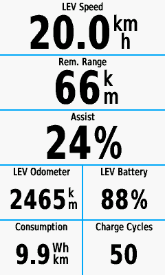
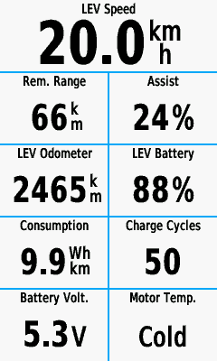
After many days testing different paths, I did understand it not possible to have the data fields on the Garmin the way it makes sense to be, simple because Garmin makes the data fields as a unique / self contained app that does not share data with the others, meaning each data field needs to have his own ANT channel which I did easily on the NRF52840 side but Garmin data fields over a number of 4 starts to fail... and the target is to have like 12. Maybe in future Garmin will improve this as there are many developers asking for data sharing between the data fields.

Now I am considering to fork and adapt for our specific motor data, the OpenSource E-Bike Edge MultiField, that is unique data field but that it self divides to show various data / data fields - this make it to be probably a full page and not be possible to mix with other data fields to design custom pages as regular other data fields work.

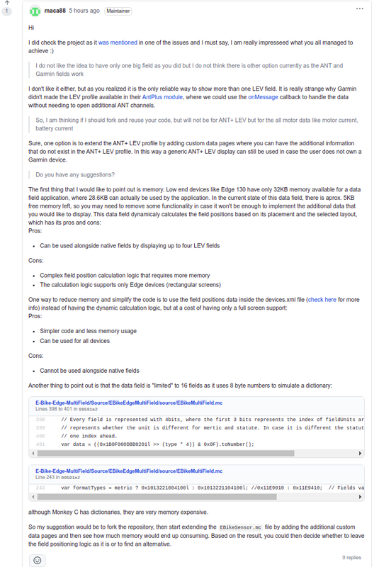
I asked to author for suggestions before I start the fork, he is very experienced because there are other data fields he developed, like one specifically to control EBike ANT+ Lights.

7FieldsA.png
9FieldsA.png
 
casainho said:
I started the TSDZ2 OpenSource firmware for the motor, displays and the wireless - I know I simple do not have life time to develop all that, but I created the seed and it is really important that others continue the development. The mbrusa firmware is using the ESP32-TSDZ2 project motor controller improvements and I used the ESP32-TSDZ2 mobile app and adapted to our wireless needs, there is a lot of crossed reuse between the projects of all this OpenSource technology, which I think is very positive!!

And all of us who are using the TSDZ2 with all the developments on it are in debted to you for all your time and input to get things going, a big thanks as we have now a very good motor that can be adapted to most peoples needs.

:thumb:
 
Waynemarlow said:
casainho said:
I started the TSDZ2 OpenSource firmware for the motor, displays and the wireless - I know I simple do not have life time to develop all that, but I created the seed and it is really important that others continue the development. The mbrusa firmware is using the ESP32-TSDZ2 project motor controller improvements and I used the ESP32-TSDZ2 mobile app and adapted to our wireless needs, there is a lot of crossed reuse between the projects of all this OpenSource technology, which I think is very positive!!

And all of us who are using the TSDZ2 with all the developments on it are in debted to you for all your time and input to get things going, a big thanks as we have now a very good motor that can be adapted to most peoples needs.

:thumb:

A big AMEN and 2nd on that! Many thanks.
 
casainho said:
After many days testing different paths, I did understand it not possible to have the data fields on the Garmin the way it makes sense to be, simple because Garmin makes the data fields as a unique / self contained app that does not share data with the others, meaning each data field needs to have his own ANT channel which I did easily on the NRF52840 side but Garmin data fields over a number of 4 starts to fail... and the target is to have like 12. Maybe in future Garmin will improve this as there are many developers asking for data sharing between the data fields.

Now I am considering to fork and adapt for our specific motor data, the OpenSource E-Bike Edge MultiField, that is unique data field but that it self divides to show various data / data fields - this make it to be probably a full page and not be possible to mix with other data fields to design custom pages as regular other data fields work.

I asked to author for suggestions before I start the fork, he is very experienced because there are other data fields he developed, like one specifically to control EBike ANT+ Lights.

7FieldsA.png
9FieldsA.png
The author gave a detailed feedback for how I should fork and insights, I think I will move forward. So good to have this help from different developers / projects:
 
Finally I found the issue with my system suddenly cut the power / make the assist level = 0 when I was braking. I kept using it because I needed it and in the end I saw more and more times the wireless remote LEDs blinking like if there was a re-initialization, when I was braking.

Turns out the battery got empty, I measured the voltage and it was clearly empty. And was very frustrating that I put a new battery and all was working up to I finally tight the final screws and suddenly it stopped working, after inspecting the battery was empty again. so it were a matter of seconds - I guess I did some short circuit with the battery wires. Finally I was more carefully and used a strong plastic take to insulate the battery wires and now the wireless remote is back again as expected.

I guess that with almost empty battery, the remote was failing when I was braking maybe because the brake RED LED is on and pulls energy. And maybe at low battery voltage the NRF52 may go crazy and maybe mistake the pins inputs? maybe it was considering I was clicking on the buttons or the brake??
 
rananna said:
Good news!
That was a difficult one to track down.
Well, guess what, after 2 hours I went to ride again and the remote was dead, no LED was light at all!! Checked again and the new battery is empty...

So, or I have an issue with my board or this batteries are not ok. I must say I did not bought them, I salvaged them from some ultra cheap Chinese products, so, maybe this batteries are manufactured to be ultra cheap and have very low capacity, enough to turn on the circuit a few times only after the client bought the product.

I need to go to local shop and buy some of this batteries that costs only 1€ to 2€ a unit. If I found the issue is with the salvaged batteries, then I need to put an alert on the documentation, there is no point to try save 1€ or 2€ on the batteries :)
 
casainho said:
rananna said:
Good news!
That was a difficult one to track down.
Well, guess what, after 2 hours I went to ride again and the remote was dead, no LED was light at all!! Checked again and the new battery is empty...

So, or I have an issue with my board or this batteries are not ok. I must say I did not bought them, I salvaged them from some ultra cheap Chinese products, so, maybe this batteries are manufactured to be ultra cheap and have very low capacity, enough to turn on the circuit a few times only after the client bought the product.

I need to go to local shop and buy some of this batteries that costs only 1€ to 2€ a unit. If I found the issue is with the salvaged batteries, then I need to put an alert on the documentation, there is no point to try save 1€ or 2€ on the batteries :)

What a pain - hopefully it's just the batteries.

I'm going to catch up with a bit of coding - so will add the missing brake LED sequence to the wired remote so then I'm all good for the release.
 
@casainho/@rananna - I'm trying the wireless update finally - how do you set the ANT_ID to 0x99? Documentation is very brief on the subject - do I need a Garmin device to do that?
 
beemac said:
@casainho/@rananna - I'm trying the wireless update finally - how do you set the ANT_ID to 0x99? Documentation is very brief on the subject - do I need a Garmin device to do that?
Short answer: using the Nordic app to modify the Bluetooth characteristic.
Longer answer: you only need 0x99 for setting the ANT ID to something other than 0 ( 0 pairs with any motor)
For all other options I simpified the operation of the wireless remote to avoid the need to use the Nordic app for configuration.
Full instructions here:
https://opensourceebike.github.io/operation.html
See configuration mode.
However, usually no configuration is necessary, it should work out if the box if you are not using a Garmin.
What are you trying to change?
 
rananna said:
beemac said:
@casainho/@rananna - I'm trying the wireless update finally - how do you set the ANT_ID to 0x99? Documentation is very brief on the subject - do I need a Garmin device to do that?
Short answer: using the Nordic app to modify the Bluetooth characteristic.
Longer answer: you only need 0x99 for setting the ANT ID to something other than 0 ( 0 pairs with any motor)
For all other options I simpified the operation of the wireless remote to avoid the need to use the Nordic app for configuration.
Full instructions here:
https://opensourceebike.github.io/operation.html
See configuration mode.
However, usually no configuration is necessary, it should work out if the box if you are not using a Garmin.
What are you trying to change?

Thanks i'm trying to flash the wireless controller fw on my test bike - because I've wrapped it in tape I wanted to update OTA. Never actually managed to get OTA working - I always flash using the STLINK...

In nrf connect - i don't see ANT ID as a parameter for the motor controller as shown in your video - just a generic unknown service in addition to the 0x1800/0x1801 name fields - it does have a single updateable parameter - currently set to 0x3. If I change this to 0x99 -the wireless controller reboots - but does not go into DFU mode...

I've disconnected the debugger just in case...

Any other handy hints :)
 
beemac said:
rananna said:
beemac said:
@casainho/@rananna - I'm trying the wireless update finally - how do you set the ANT_ID to 0x99? Documentation is very brief on the subject - do I need a Garmin device to do that?
Short answer: using the Nordic app to modify the Bluetooth characteristic.
Longer answer: you only need 0x99 for setting the ANT ID to something other than 0 ( 0 pairs with any motor)
For all other options I simpified the operation of the wireless remote to avoid the need to use the Nordic app for configuration.
Full instructions here:
https://opensourceebike.github.io/operation.html
See configuration mode.
However, usually no configuration is necessary, it should work out if the box if you are not using a Garmin.
What are you trying to change?

Thanks i'm trying to flash the wireless controller fw on my test bike - because I've wrapped it in tape I wanted to update OTA. Never actually managed to get OTA working - I always flash using the STLINK...

In nrf connect - i don't see ANT ID as a parameter for the motor controller as shown in your video - just a generic unknown service in addition to the 0x1800/0x1801 name fields - it does have a single updateable parameter - currently set to 0x3. If I change this to 0x99 -the wireless controller reboots - but does not go into DFU mode...

I've disconnected the debugger just in case...

Any other handy hints :)

I might just add a button sequence on power-up. I know from reading the back thread that this has been suggested in the past and discounted - but I think it makes life a lot easier... Only need one app -nrf toolbox - much less fiddling..
 
Back
Top