galp
100 W
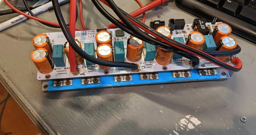
Read about HW bugs here: http://pavlin.si/besc/besc-g2/

galp said:24S should be okay but I wouldn't go much higher.
owhite said:Thanks. I've tried a few things but so far I've only gotten about 40 amps max. I'm still getting 50 mph which is good but would to like to know why I cant achieve more. Hopefully Galp will make an appearance with some suggestions.
Also, I'm beginning to suspect the quality of my batteries so I ordered new ones.
galp said:Check your duty cycle. If it's near 95% this means the motor cant spin any faster and that's the reason it is not drawing more current. If not there must be something throttling the current.
- Check what motor temperature you get
- Check what mosfet temperature you get
- Check your battery voltage cutoffs
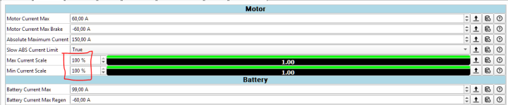
- Check the current scaling
owhite said:erdogank --
I just got a massive increase in performance from setting:
motor current max = 200
battery current max = 200
My bike is 43 kg and I got it up to 72kph and THEN the front wheel started to lift up off the ground. At that point I was paying more attention to staying alive so I'm not sure about the amps, but later on I was pulling 80amps at maybe 75% throttle. I also made minor changes to the throttle curve:
https://i.imgur.com/XgZvnOV.png
which I believe just made it more aggressive, but was probably not the cause of power increase. I think that should help with your slow starts. What are your motor and battery current max settings?
erdogank said:owhite said:erdogank --
I just got a massive increase in performance from setting:
motor current max = 200
battery current max = 200
My bike is 43 kg and I got it up to 72kph and THEN the front wheel started to lift up off the ground. At that point I was paying more attention to staying alive so I'm not sure about the amps, but later on I was pulling 80amps at maybe 75% throttle. I also made minor changes to the throttle curve:
https://i.imgur.com/XgZvnOV.png
which I believe just made it more aggressive, but was probably not the cause of power increase. I think that should help with your slow starts. What are your motor and battery current max settings?
Hi owhite, motor and battery current max are 193A,ADC Control Type is Current,
my bike is 90kg quad bike and with my old 3kw bldc controller I have no slow start.
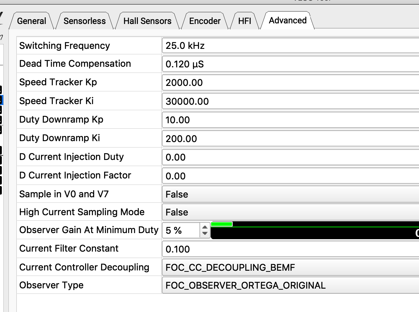
What are your Switching Frequency, Dead Tiem Compansation parameters?
My Motor and App configuration are attached.
owhite said:switching frequency:
attachments:
marin_bike.xml
marin_bike_app.xml
there's no bluetooth module on the G2 -- the only connection available for the VESC-tool is the USB port into the board.1.Vesc Tool Android apk not connecting to BT module, did you use this apk?
I have not used ebrake and I dont have a lot of familiarity with how they work on VESCs. Are you using J13 / throttle 2?2.Brake issue, VESC I think is not designed for ebike,I solved it with small circuit using opamp, how did you solve it?
I dont see why you couldn't use water cooling. I agree with your approach, If I was going to try that the first thing I would try would be a CPU cooling blocks and to mount them on an aluminum plate which is bolted to the MOSFETs.3.Mosfet heating, I want to cool them using water cooling as it is used in PC CPU cooling, what do you think about?
only work with nrf51822 BT module not working with HM-10 BT module
owhite said:only work with nrf51822 BT module not working with HM-10 BT module
erdogank -- did you add a nrf51822 module to the BESC G2, or are you using some other VESC that has this module?