True FOC: definition and examples

everythingisawave said:
marka-ee said:
Yes, I guess. So is that really what the FOC is doing, just moving the hal timing a little to compensate for the current lag? Boiling it down to the simple here. Does the ultimate FOC implementation modify the shape of the sine wave being generated?
The 'field weakening' still eludes me. Maybe field weakening involves more than a timing change ( read: phase change ) and actually changes the shape of the output to the motor phase wire.
So in summary: FOC at first approximation is nothing more that optimized hal timing. That I can code and to hell with the vector theory. None of this interests me if it does not increase range or speed measurably.

The modification is done during the PWM generation, in a separate process. The decision on suitable reference currents and voltages is unaffected.

I guess you can consider it as a being able to control timing and magnitude in a very smooth way, although IMHO it's not really possible to fullly understand FOC without vector theory (yes, mental gymnastics needed :( ). It does increase maximum speed and range, which is why it is defacto standard for higher power machines and servomotors. Cost and development effort is higher for software, sensors etc. although that cost is coming down as an industry trend.

The FOC has no awareness of timing. It takes the angle for timing from the halls and/or observer. FOC and timing/phase are independent.

FOC operates on two orthogonal vectors, id and iq, and since they are orthogonal they do not influence each other. If your timing is wrong, the FOC loop will not know and the only effect is that the magnitude of Vd will increase and the Vq will decrease to maintain the same currents.
 
everythingisawave said:
It does increase maximum speed and range
This is right in comparison to simple six step commutation, but not in comparison to the sinusoidal commutation that Kunteng does on their sinewave controllers. There is more than one way, to determine the needed advance angle...

https://www.ti.com/lit/an/slaa699/slaa699.pdf?ts=1617720028031&ref_url=https%253A%252F%252Fwww.google.com%252F

advance angle.JPG

mxlemming said:
FOC and timing/phase are independent.
Yes, this is the trick that the FOC does. You get values in the rotating frame, that are not depending on time.
Nevertheless, the timing is extremly important. You have to know the rotorposition exactly, otherwise FOC can't work. It's in the name already: field oriented control....

regards
stancecoke
 
mxlemming said:
The FOC has no awareness of timing. It takes the angle for timing from the halls and/or observer. FOC and timing/phase are independent.

FOC operates on two orthogonal vectors, id and iq, and since they are orthogonal they do not influence each other. If your timing is wrong, the FOC loop will not know and the only effect is that the magnitude of Vd will increase and the Vq will decrease to maintain the same currents.

Technically by changing the Idq current vector angle you are changing the "timing" (taking this as a mental vehicle in this context), so while the dq part of the loop has no control over the basis vector angle, it does have control over your vector angle relative to the magnet flux.

The word "timing" is so vague though and leads to all these semantic issues, we should really deprecate its use :confused:
 
everythingisawave said:
mxlemming said:
The FOC has no awareness of timing. It takes the angle for timing from the halls and/or observer. FOC and timing/phase are independent.

FOC operates on two orthogonal vectors, id and iq, and since they are orthogonal they do not influence each other. If your timing is wrong, the FOC loop will not know and the only effect is that the magnitude of Vd will increase and the Vq will decrease to maintain the same currents.
Technically by changing the Idq current vector angle you are changing the "timing" (taking this as a mental vehicle in this context), so while the dq part of the loop has no control over the basis vector angle, it does have control over your vector angle relative to the magnet flux.

The word "timing" is so vague though and leads to all these semantic issues, we should really deprecate its use :confused:

While this is true, doing so would trash the point of FOC. The control algorithms would be odd at the least, field weakening and MTPA would become difficult to compute (you'd probably end up realigning your computation with the real rotor angle...)

I don't think it's useful to think about it in terms like this.

Timing = the correlation between the angle your controller thinks the rotor is vs the angle it really is. For 6 step timing is very important since switching at the wrong time wreaks havoc since large pwm voltage with small back emf results in big current spikes. For FOC, there is no discontinuous calculation so its much more forgiving, it just results in poor efficiency.

Actually I found FOC easier to implement than 6 step BLDC and easier to debug. To run phase advance with BLDC you pretty much have to make an angle interpolator or have discontinuous logic to advance by a full step and then delay or... Something complicated that by the time you've done it you might as well find the real angle and do 4 trig transforms like you learnt age 17 at school.
 
stancecoke said:
mxlemming said:
By contrast, stancecoke lishui foc is easy to follow but less complete
Hm, it's fully working :). But of course some features like field weakening or detection of motor inductance and resistance are not implemented. I don't need this features :lol:

It has a user friendly GUI with an up to date wiki to set up your system. It should be usable even for people with no computer skills :wink:
And it works with cheap and widely available China hardware, that is used by many european Ebike OEMs like Prophete, Fischer, NCM...

regards
stancecoke

68747470733a2f2f7777772e706564656c6563666f72756d2e64652f77696b692f6c69622f6578652f66657463682e7068703f63616368653d266d656469613d656c656b74726f746563686e696b3a677569626173696373657474696e67732e706e67

I quite like what you did here and especially the proper ebike features that you implemented (torque sensor, speed limit, assist level selection), but I dislike the hardware. It is quite expensive and not really All that powerful.
What I dream of at night is a board capable of ~25 batt amps and 50v that Will run the firmware you made :)
 
Vbruun said:
~25 batt amps and 50v that Will run the firmware you made

@slipy has build a 12FET version already as far as I know, I don't know, if he has tested it yet.

https://endless-sphere.com/forums/viewtopic.php?f=30&t=109578

regards
stancecoke
 
Vbruun said:
I quite like what you did here and especially the proper ebike features that you implemented (torque sensor, speed limit, assist level selection), but I dislike the hardware. It is quite expensive and not really All that powerful.
What I dream of at night is a board capable of ~25 batt amps and 50v that Will run the firmware you made :)

I have 18mos board, not tested yet but smaller version for hailong was builded with using same scheme. My board up to 110v (but i haven't so high voltage mosfets only up to 100v)
 
Forgive me for simplifying the FOC to just a 'timing' change, but where the code meets the mosfets, isn't that what is exactly happening? You start producing the sine wave a wee bit earlier that before. I was wondering though, do cheap KT controllers do any kind of timing advance at all to even in the grossest way get a little more optimal results?
 
marka-ee said:
Forgive me for simplifying the FOC to just a 'timing' change, but where the code meets the mosfets, isn't that what is exactly happening? You start producing the sine wave a wee bit earlier that before.

Yes, good point. This is what is happening. When explaining to students I often tell them that aligning the rotor position sensor is akin to adjusting the engine timing, it really helps mechanics and non-EE engineers to understand its importance. Whatever helps you understand:)
 
marka-ee said:
do cheap KT controllers do any kind of timing advance at all

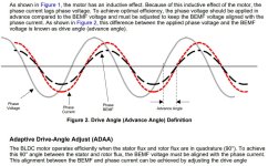
Yes, I think so. I don't know how the original Kunteng firmware manages it, in the open firmware, we look at the zero crossing of the current on one phase wire and syncronize it with a defined rotor position. The BEMF is strictly depending on the rotor position, so we can shift the voltage vector according to the picture qouted above from the TI paper.

regards
stancecoke
 
Long time ago when college was free i learnt about power factor and how we use capacitance resistance and inductance to limit the lag of current or voltage in a circuit to make it more efficient.

We done a bit of work on the local mill improving around 100 of the existing induction motors about 50kw in total and saved thousands in electric per year what we have here is capable of saving many thousands more, My lot just fixed the system as a whole the foc controlling method saves energy direct at source output meaning even the motors get power factor correction theres minimum waste heat and noise for a more plesent steel smelting enviroment lol.
 
Question...

Is there a convention for current flow into a motor with FOC? Or in general? At present, I've defined higher voltage on ground referenced shunts as positive, which corresponds to current out of the motor is positive.

From an outside perspective, this works fine. You can't tell. When programming, it makes no odds provided you're consistent... Presumably it makes the rotor rotate the opposite direction and 180 degrees out of phase or something, assuming you've arbitrarily defined phase in some way or could instantaneously switch your paradigm and watch the carnage unfold.

I notice from the code that VESC has made the opposite choice. The st code has it buried into piles of library options for 1 million option cross compatibility, maybe I'll look tomorrow...

Is there any conceivable reason this would matter?
 
Hummina Shadeeba said:
How likely and soon do you think till a reliable field-weakening program for the Vesc? I need 20% more speed!
The dev branch has FW support, its being tested by a few users now. We tested at 150 FW Amps, and at 30A in an ebike setup, cant find anything wrong so far. MTPA needs to be disabled until we contribute a small fix.
 
Tiny and cheap VESC 72V 100A (phase amps or battery? )

https://endless-sphere.com/forums/viewtopic.php?p=1677954#p1677954

Question, being VESC, automatically means yes "true FOC"?
 
john61ct said:
Tiny and cheap VESC 72V 100A (phase amps or battery? )

https://endless-sphere.com/forums/viewtopic.php?p=1677954#p1677954

Question, being VESC, automatically means yes "true FOC"?

VESC = true FOC. Yes.
 
mxlemming said:
VESC = true FOC. Yes.

Any chance you could make a layman's translation of this distinction here?

https://endless-sphere.com/forums/viewtopic.php?p=1681434#p1681434
 
john61ct said:
mxlemming said:
VESC = true FOC. Yes.

Any chance you could make a layman's translation of this distinction here?

https://endless-sphere.com/forums/viewtopic.php?p=1681434#p1681434

In that topic i wrote:
Re. The FOC, you don't need that many samples. The current measurements are just for feedback, regulation... The algorithm will run many many pwm cycles without a current measurement before error occurs as long as your motor is sufficiently sinusoidal and has a non tiny inductance. Normally FOC controllers will sample at dead center of the low side FETs freewheeling period. The current is then the average current in the middle of the ramp down period and is the same as during the high side FET freewheeling period.

Translating this into layman's terms I wouldn't describe as trivial, but I'll try.

first, what is FOC
FOC works at a physical level by generating a voltage sinusoid, synthesized by PWM, which it orients relative to the magnetic field of the rotor.

what's the FOC algorithm doing
It takes current measurements as an input and adjusts the phase and amplitude of the voltage sinusoid such that rather than it being the voltage that is locked in phase with the magnetic field it is the resulting current sinusoid that's locked in.

less layman
The math inside this relies on the fact that two sinusoids added together can be expressed as one sinusoid with a different phase and amplitude, or indeed 3 sinusoids with different phase and amplitude, and that by knowing the angle of the rotor you can apply a rotation matrix to remove the rotation before doing the control math and then adding the rotation back again.

why doesn't it need so many current samples?
But once it has determined the phase and amplitude of the voltage sinusoid it needs to cause the current sinusoid, it can continue to generate said voltage sinusoid and the current sinusoid will maintain in phase until an external factor changes. All that needs to be done is that the sin wave is advanced with every pwm period by the amount the angle of the rotor has advanced, which is information provided by an encoder, hall sensors with interpolation or a sensorless observer.

Observers practically require information to observe, and therefore my statement above doesn't really hold for sensorless control, but FOC is strictly not about the mechanism used to know the rotor angle.

I don't think i can do more layman than this.

phase vs low side shunt
In terms of phase vs low side shunt, low side is only able to measure current during the pwm low, phase shunt can measure it any time. This doesn't really matter, since the FOC is perfectly happy to continue blindly advancing the voltage sin wave until it next gets a current sample, when it will adapt the sin wave it's generating.
An intricacy here is that usually FOC ESCs use center aligned pwm (though it doesn't have to) which means you can update the pwm duty cycle more than once per pwm period. With low side shunt you get one current sample per pwm period, with phase shunt you can get two (assuming your goal is to sample in the middle of switching there MOS on/off to avoid noise, pedants might point out your ADC can sample current as often as it wants during each pwm cycle).
 
Wow, yes thanks for trying, but I did not grok any of that, at all.

If I were to try googling for textbooks and courses that would get me started

not necessarily MIT level stuff but

at least approaching understanding the jargon

what are the course / program keywords / names?

Besides electrical motors of corse

Some subset / intersection of mechanical and electronic engineering...
 
john61ct said:
Wow, yes thanks for trying, but I did not grok any of that, at all.

If I were to try googling for textbooks and courses that would get me started

not necessarily MIT level stuff but

at least approaching understanding the jargon

what are the course / program keywords / names?

Besides electrical motors of corse

Some subset / intersection of mechanical and electronic engineering...

I taught myself this mid 2020 from scratch. My sources were:
Wikipedia
Switchcraft
The Infineon code libraries

I spent an awful lot of time trying to understand it from various sources and never did. Then one evening I sat down with a working inverter and just wrote the code for it. 12 hours later (spread over 2 evenings) i was like... "Oh, I have working FOC and it really wasn't that hard".

In the end, FOC is:
Know angle (this is actually far harder that the FOC itself)
Measure currents (trivial in code when using stm32, there are libraries that set that up in like 5 lines of code)
Do 10 multiply and adds
Run a PID loop
Do another 10 multiply and adds
Set the new PWM values.
 
mxlemming said:
I taught myself this mid 2020 from scratch.

LOL we have a skyscraper's worth of difference of meaning of "scratch"

I did not even mean understanding FOC itself,

I am a near complete noob with motors and controller basics, barely remember any high school math

I just meant the 101-level understanding of overall electric motor basics, so I could grok these ideas from a user POV. I'm not a coder either, not planning on inventing anything.

To illustrate, I know shunts from using battery monitors & ammeters, but no idea what "phase vs low side" might mean.

I do not yet grasp the meaning of any of these terms:

sinusoidal, sinusoid, voltage sinusoid, adding?
sin wave, advancing the voltage sin wave
inductance
ramp down
locked in phase, different phase, maintain in phase
apply a rotation matrix
remove the / adding the rotation
control math
encoder, hall sensors with interpolation, sensorless observer, sensorless control
ESCs

And I barely grok these, from other contexts:

FET, ADC
pwm, center aligned pwm, dead center,
pwm period, update the duty cycle
low vs high side
sample in the middle of switching
rotor, rotor angle, advance the angle


john61ct said:
If I were to try googling for textbooks and courses that would get me started

not necessarily MIT level stuff but

at least approaching understanding the jargon

what are the course / program keywords / names?

Besides electrical motors of corse

Some subset / intersection of mechanical and electronic engineering...


Might be worth Google image searching those terms if you're a visual person. From pictures you find the words can start having much more meaning. I bookmarked this page to do exactly this when I have time.
 
I prefer to spend a few months going through course materials, following a well planned curriculum ideally from well recognized universities.

I just don't even know what kind of courses teach this stuff.
 
Many moons ago i done a 3 year industrial installation engineer course in uk without that i would be nothing, first year is basic learnt SI units and formula transposition, ohms law, flemmings left hand rule then built upon that, we touched on all aspects of an installation be it what type of light to use types of cable fire proof etc earthing arrangements and motors inductors and the basic meat of most aspects.

From that ive built on my understanding of motor principles massively by pushing them past their limits in my own use cases theres nothing like hands on experience but from all that i know what your attempting is no easy task ive never touched indepth coding myself but im no stranger to a computer.

I helped crack gran turismo 5 back in the day with a brute force save decryption tool then using hexadecimal file compare and using trial and error i managed to find secrets within the game that was eaisly unlocked by changing the value within the box it was possible to make custom cars using the games engine to swap attributes so a fiat 500 coild have an f1 engine and downforce levels.

I imagine its simular what can sniffers do finding saving data sets and backwards engineer whats going on maybe thats an approach you could take to get a picture of whats going on in source code.

As for the motors learn the fundamental basic differences of a brushed dc motor and soecislly how the commutor is flipping the poles and manually creating a dc sinusoidal wave becuase of its inductance even when been fed a pwm signal then the squrrel cage on induction motors along with bldc then see if what you have in your head you can understand how the relctance motor works at that point you got a decent understanding of the internal workings the relationship between turns and rpm etc and should be able to get your head around the task.
 
Ianhill said:
Many moons ago i done a 3 year industrial installation engineer course

OK I'd never heard of "installation engineer" seems to be a type of mechanical engineer, but courses are not necessarily focused on electric motors.

Maybe a UK specific term?

Some googling leads me to "Power Electronics", seems more EE than ME?

are these "variable frequency drive" controls?

Related terms I don't know yet:

"3 phase induction"?

series vs parallel dc motor?

single phase ac motor?


Back
Top